

- Joined
- Jul 21, 2014
- Messages
- 10,414
- Reaction score
- 165
Following on from my router circle cutter jig here https://www.thewoodhaven2.co.uk/threads/yet-another-router-circle-cutting-jig.9460/
It was time to put it to its first task that I built it for.
I wanted to display a novel clock (details later) that had an exposed mechanism requiring a well oiled roller chain that I need to protect from gathering dust. It is quite tall and yet narrow so I found the nearest sized glass dome on eBay but it still would not be quite deep enough to prevent the chain touching the glass. Although the dome came with mediocre wooden base, I needed a custom base to win some extra height.
This is the cross section I came up with.

The 4mm wide groove at the top locates the dome and the off centre 70mm diameter recess 19mm deep wins me the extra space needed to accomodate the clock height.
The 22.5 mm x 10mm recess in the underside gives me room for led illumination and some electronics to regulate the brightness and to supply the clock mechanism
Not being a proficient wood turner I decided on the router approach. I needed to centres of rotation, one for the bulk of the wood removal and an offset on for the 70mm recess.

Here is the pine protoype part way through the process showing the two centres of rotation. The offset on is a blind hole but the main one goes right through to give me a centre on the underside as shown below.

after the 70mm recess edge had been cut, I could then free hand rout away the boss to complete the recess and check for fit and function.
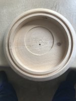
not very pretty but this was the prototype* and I learned lots and planned to refine the process.
*Actually the second prototype as the first had a few fundamental cock-ups and was despatched to the scrap bin
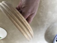
I also experimented with cutting a fluted edge on the periphery and a chamfer to blend it in to the glass groove.
Have sorted out my methods its fast forward to the final model made from oak with a few coats of water based PU varnish on the outside surefaces and sprayed matt black on the inside to remove spurious reflections.
A semi-circle of 3mm holes locate 24 warm white LEDS around the front half to show off the clock.
The timekeeping part of the clock is a pretty standard quartz mechanism with the slightly unusual featrue that the sweep second hand moves smoothly not in steps.
The based of the clock looks to be a genuine 125cc motorcycle piston an faux con rod and timing gears but with genuine double row roller chain as would be used in an IC engine. A small discretely mounted motor drives the "crankshaft" gear that in turn drive the top "camshaft" gear that curiously has a genuine ball race at its centre. All together a quite striking (no pun intended) clock.
Nicely thought out to have the smooth sweep second hand nearby to the smoothly turning gear. Would not look right to have the second hand going in steps
Here it is switched off.

Once I've discovered how to add a video file I'll show a clip of it working....
Bob
It was time to put it to its first task that I built it for.
I wanted to display a novel clock (details later) that had an exposed mechanism requiring a well oiled roller chain that I need to protect from gathering dust. It is quite tall and yet narrow so I found the nearest sized glass dome on eBay but it still would not be quite deep enough to prevent the chain touching the glass. Although the dome came with mediocre wooden base, I needed a custom base to win some extra height.
This is the cross section I came up with.
The 4mm wide groove at the top locates the dome and the off centre 70mm diameter recess 19mm deep wins me the extra space needed to accomodate the clock height.
The 22.5 mm x 10mm recess in the underside gives me room for led illumination and some electronics to regulate the brightness and to supply the clock mechanism
Not being a proficient wood turner I decided on the router approach. I needed to centres of rotation, one for the bulk of the wood removal and an offset on for the 70mm recess.
Here is the pine protoype part way through the process showing the two centres of rotation. The offset on is a blind hole but the main one goes right through to give me a centre on the underside as shown below.
after the 70mm recess edge had been cut, I could then free hand rout away the boss to complete the recess and check for fit and function.
not very pretty but this was the prototype* and I learned lots and planned to refine the process.
*Actually the second prototype as the first had a few fundamental cock-ups and was despatched to the scrap bin
I also experimented with cutting a fluted edge on the periphery and a chamfer to blend it in to the glass groove.
Have sorted out my methods its fast forward to the final model made from oak with a few coats of water based PU varnish on the outside surefaces and sprayed matt black on the inside to remove spurious reflections.
A semi-circle of 3mm holes locate 24 warm white LEDS around the front half to show off the clock.
The timekeeping part of the clock is a pretty standard quartz mechanism with the slightly unusual featrue that the sweep second hand moves smoothly not in steps.
The based of the clock looks to be a genuine 125cc motorcycle piston an faux con rod and timing gears but with genuine double row roller chain as would be used in an IC engine. A small discretely mounted motor drives the "crankshaft" gear that in turn drive the top "camshaft" gear that curiously has a genuine ball race at its centre. All together a quite striking (no pun intended) clock.
Nicely thought out to have the smooth sweep second hand nearby to the smoothly turning gear. Would not look right to have the second hand going in steps
Here it is switched off.
Once I've discovered how to add a video file I'll show a clip of it working....
Bob


 and clever design.