• Hi all and welcome to TheWoodHaven2 brought into the 21st Century, kicking and screaming! We all have Alasdair to thank for the vast bulk of the heavy lifting to get us here, no more so than me because he's taken away a huge burden of responsibility from my shoulders and brought us to this new shiny home, with all your previous content (hopefully) still intact! Please peruse and feed back. There is still plenty to do, like changing the colour scheme, adding the banner graphic, tweaking the odd setting here and there so I have added a new thread in the 'Technical Issues, Bugs and Feature Requests' forum for you to add any issues you find, any missing settings or just anything you'd like to see added/removed from the feature set that Xenforo offers. We will get to everything over the coming weeks so please be patient, but add anything at all to the thread I mention above and we promise to get to them over the next few days/weeks/months. In the meantime, please enjoy!

Help with new NVR switch, please.

Mike G

Petrified Pine
Joined
Jul 30, 2014
Messages
12,600
Reaction score
3,248
Location
Suffolk
Name
Mike
I have finally bought a new NVR switch for my bandsaw, after years of using the switch on the socket to turn the machine off. Unfortunately, it has a different arrangement of terminals than the old one, and unfortunately, I didn't take a photo of that. I'm not sure how much that would help anyway as there is no wiring diagram on the old switch.

Could someone please tell me which wires go on which terminals. Obviously the two red wires have to be one on the "in" side of the switch, and one on the "out".......but that's as far as I've got.


eHj284o.png

rZCcuFZ.png
 
Mike,

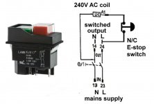
You need to know which lead comes from the plug, that goes to pins 13 and 23 on the switch while the cable that goes to the motor is connected to 14 and 24.
I could pop over with my test meter to check the wires if you not sure which is which.
 
That's surely black and red to the plug, isn't it? It's a sealed-for-life plug, but if it came to it I could cut it off and put a new one on.
 
Mike G":35edk6vx said:
That's surely black and red to the plug, isn't it? It's a sealed-for-life plug, but if it came to it I could cut it off and put a new one on.
Well if the machine was made in the UK, yes, but other places use all sorts of different colour codes!
 
That sort of switch is intended for use with a motor with integral thermal overload switch.
Yours does not look to be that type of motor as you only (possibly) have two leads going to the motor.

To convert the switch to a "4 terminal" instead of a 5 terminal one, you need to connect A1 to 24 and as well as 23 & 24 to the motor and the remaining two contacts to the incoming supply as Dave has indicated. Polarity is not important.

HTH
Bob
 
There is a cut-off switch on the cabinet door in the equation, too.

I've tested all the wires there, and only one seems to be coming from the plug. The white wire is from the plug's live pin.....none of the others light up with my makeshift battery-and-bulb test kit.
 
So if that diagram is correct, the other leg of the mains goes directly though the door interlock switches. So if you close the doors can you find the neutral pin of the plug connected to one of the other wires?
 
No, I couldn't. My test kit is somewhat rudimentary, though.
 
Ever since the days of digital cameras I always take a picture before I disconnect anything ... :eusa-whistle:

Does this help?

21CBE438-1EFE-4313-A78C-0462265A433B.jpeg
 
The plot thickens. I have managed to get into the bowels of the machine. Here is the supply to the motor:

gduRPFx.png

Much more significantly, this thing, a "magnetic contactor" is the hub of all the wiring:

HCsvX7g.png

The brown and blue here are definitely power in:

gLM3vGG.png

And these three (black, red & white under my finger) are the wires that go up to the switch position:

2uaUPUA.png

I can't see the wires from the micro-switch on the cabinet door.
 
Are you sure the broken switch was a NVR type?

And is that the right model at Axminster you linked to?

Just thinking if there is a contactor then that might be doing the NVR function.
 
I'm no longer sure about anything at all, Robert.
 
Do you still have the old switch and if so is there any diagram on it? Any model plate on the saw?

Now you have better access to the wiring you could probably do a diagram of the existing wires so we know what goes where.
 
The old swith is clearly, in hindsight, not an NVR switch. That function is taken by the box of tricks which all the wires connect to. Anyway, here's the old switch.

gGoqwA9.png

LsvHH07.png

The problem which looms now is that it may be the box of tricks which has failed, rather than the switch. As I said, turning it on works, but I have to turn off via the socket.
 
Mike,

Would you like me to collect some bits together and pop over to sort your saw out? It will probably only take an hour, oh and a mug of coffee!
 
If you're not doing anything Dave, that would be brilliant. I've just finished work for the day.....
 
If it’s not too much trouble could the solution be posted, it could help others in future. ;)
 
Huge thanks, Dave. Much appreciated.

We're nearly up and running, folks. Just a mis-shaped thingy on the door not properly triggering the micro-switch, and I'll tackle that tomorrow.
 
Woodster":12607tye said:
If it’s not too much trouble could the solution be posted, it could help others in future. ;)

The magnetic contactor was faulty. The switch wasn't an NVR switch, but s simple on-off switch, with the NVR function being carried out by the contactor. With that failing, Dave suggested just re-wiring the machine using the new NVR switch, and binning the contactor. This simplifies things, but it did involve an hour or two of work, some new flex, and some terminal blocks. Once the trigger for the door switch is sorted out it should be a robust alternative to the original wiring.
 
Back
Top