

Some years ago, I indulged my interest in old woodworking gear and bought myself a treadle-operated fretsaw. Not because I especially want to produce loads of fretwork, but just because it was pretty, cheap and not something you see very often. Here's a general view of it in use, cutting the waste from a dovetail.
It's a "Fleetwood" made by the Trump Brothers of Wilmington, Delaware. I wonder what became of the family?

Much as I like it, it's showing its age, which is probably over a century - here it is in an 1884 catalogue (from the ever-useful http://www.vintagemachinery.org/pubs/de ... x?id=20770.)

Note that mine lacks the drill attachment and the blower (though I did build my own blower with bits of an old blowlamp).
The trouble is that the blade wobbles about fore and aft. I think this is because the upper blade support has worn the hole that it runs in. If I press the guide rod one way, you can see a definite gap

which shows at the front if I push the other way

So, I decided that I needed to do something about that wobble and wear. I could see two options. I could open out the oval hole and insert a bushing to make it round again. That would need quite a lot of metal removing from the casting, then a bit of precision work. Alternatively, I could open out the hole by the bare minimum and make a bigger guide rod which fitted in it. That sounded easier, so I did.
The current guide rod measures 5/16" so the next size up is 11/32". I don't have a reamer that size, so I popped in to Bristol Design, had a rummage through the right drawer and bought one.
The cast iron responded nicely, as I worked my way down from the top
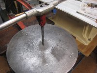
and up from the bottom

With that done, it was over to the lathe for some more treadling:


Here I am checking for size with a micrometer, set to the diameter of the reamer, 0.3437" or thereabouts

Having got as close as I dared with the lathe tools, I finished off with a file. This was a normal thing to do when this lathe was new and surface finish was not all it might be. In this posed photo I am using one hand to hold the camera, but rest assured my filing technique was two-handed and more careful than this looks. I checked with a proper straight edge and couldn't see any light.

Some more filing produced the little ball on the end

and a trial fit showed that it was worth carrying on

The bottom end of the rod needs to be reduced to half and have a notch filed in. This was an excuse to play around with my selection of old marking kit. I'm sure a proper engineer would have done a better job, but I was happy to fiddle about, finding the centre by eye rather than numerical measurement.
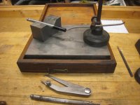
Then it was just hacksawing and filing until I had something that looked about right and would fit on the end of the long spring that lifts it up.

Having revealed a flat surface, I avoided the challenge of accurately cross-drilling into the rod, and could just locate a centre punch by poking it through the bit of the blade clamp it forms. Then it was time for the drilling machine, which shares the same universal power pack as the other tools used on this project:


Here is the new rod alongside the original.

Attentive readers can admire the neatly tapped hole in the new one. Rest assured I soon realised that it needed to be a clearance hole, so I bored it out again.
When I tried reassembling the saw, it soon became clear that my new rod was not too loose, but the opposite. Part of my cunning plan was that for quite a few years I have had this tin knocking about waiting to come in useful.
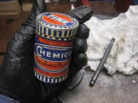
In all my years of owning a car, I have never needed to regrind the inlet and outlet valve seatings and I am confident in saying that I never will. But it was just what I needed for this. I could feel how it filled up the gaps between the two parts, but with sufficient twiddling and pushing and pulling, I could remove a little of the metal, exposing it as a dull grey dust. I wiped everything down with WD40, then lubricated with oil, then repeated a couple of times, until it felt like everything was moving freely.
Here's the rod after lapping, looking grey where it had been shiny

and here it all is, assembled and working.

I expect some more running in and fiddling will get it even better, but I'd rather creep up than go too far. It works as well as I need it to
Fundamentally, the design is not as good as that of firms like Hobbies, which had a better blade tensioning system and parallel motion. But I don't have room for two of these beasts!
It's a "Fleetwood" made by the Trump Brothers of Wilmington, Delaware. I wonder what became of the family?
Much as I like it, it's showing its age, which is probably over a century - here it is in an 1884 catalogue (from the ever-useful http://www.vintagemachinery.org/pubs/de ... x?id=20770.)
Note that mine lacks the drill attachment and the blower (though I did build my own blower with bits of an old blowlamp).
The trouble is that the blade wobbles about fore and aft. I think this is because the upper blade support has worn the hole that it runs in. If I press the guide rod one way, you can see a definite gap
which shows at the front if I push the other way
So, I decided that I needed to do something about that wobble and wear. I could see two options. I could open out the oval hole and insert a bushing to make it round again. That would need quite a lot of metal removing from the casting, then a bit of precision work. Alternatively, I could open out the hole by the bare minimum and make a bigger guide rod which fitted in it. That sounded easier, so I did.
The current guide rod measures 5/16" so the next size up is 11/32". I don't have a reamer that size, so I popped in to Bristol Design, had a rummage through the right drawer and bought one.
The cast iron responded nicely, as I worked my way down from the top
and up from the bottom
With that done, it was over to the lathe for some more treadling:
Here I am checking for size with a micrometer, set to the diameter of the reamer, 0.3437" or thereabouts
Having got as close as I dared with the lathe tools, I finished off with a file. This was a normal thing to do when this lathe was new and surface finish was not all it might be. In this posed photo I am using one hand to hold the camera, but rest assured my filing technique was two-handed and more careful than this looks. I checked with a proper straight edge and couldn't see any light.
Some more filing produced the little ball on the end
and a trial fit showed that it was worth carrying on
The bottom end of the rod needs to be reduced to half and have a notch filed in. This was an excuse to play around with my selection of old marking kit. I'm sure a proper engineer would have done a better job, but I was happy to fiddle about, finding the centre by eye rather than numerical measurement.
Then it was just hacksawing and filing until I had something that looked about right and would fit on the end of the long spring that lifts it up.
Having revealed a flat surface, I avoided the challenge of accurately cross-drilling into the rod, and could just locate a centre punch by poking it through the bit of the blade clamp it forms. Then it was time for the drilling machine, which shares the same universal power pack as the other tools used on this project:
Here is the new rod alongside the original.
Attentive readers can admire the neatly tapped hole in the new one. Rest assured I soon realised that it needed to be a clearance hole, so I bored it out again.
When I tried reassembling the saw, it soon became clear that my new rod was not too loose, but the opposite. Part of my cunning plan was that for quite a few years I have had this tin knocking about waiting to come in useful.
In all my years of owning a car, I have never needed to regrind the inlet and outlet valve seatings and I am confident in saying that I never will. But it was just what I needed for this. I could feel how it filled up the gaps between the two parts, but with sufficient twiddling and pushing and pulling, I could remove a little of the metal, exposing it as a dull grey dust. I wiped everything down with WD40, then lubricated with oil, then repeated a couple of times, until it felt like everything was moving freely.
Here's the rod after lapping, looking grey where it had been shiny
and here it all is, assembled and working.
I expect some more running in and fiddling will get it even better, but I'd rather creep up than go too far. It works as well as I need it to
Fundamentally, the design is not as good as that of firms like Hobbies, which had a better blade tensioning system and parallel motion. But I don't have room for two of these beasts!


