What I ment was that a composite cedar strip boat with epoxy glass is best as that without mixing capping rails screwed through the epoxy glass.Aesthetics, mainly, (I'm not confident of getting a neat-looking fibreglass joint), but a secondary waterproofing for the joint.
I'm not sure what the correct description is, but "strong" or "rigid" are the starting points. Bear in mind the size. This is smaller than almost any wooden dinghy or tender you can think of, and has got a strong structural bulk-head only 1.8m from the front.
-
Hi all and welcome to TheWoodHaven2 brought into the 21st Century, kicking and screaming! We all have Alasdair to thank for the vast bulk of the heavy lifting to get us here, no more so than me because he's taken away a huge burden of responsibility from my shoulders and brought us to this new shiny home, with all your previous content (hopefully) still intact! Please peruse and feed back. There is still plenty to do, like changing the colour scheme, adding the banner graphic, tweaking the odd setting here and there so I have added a new thread in the 'Technical Issues, Bugs and Feature Requests' forum for you to add any issues you find, any missing settings or just anything you'd like to see added/removed from the feature set that Xenforo offers. We will get to everything over the coming weeks so please be patient, but add anything at all to the thread I mention above and we promise to get to them over the next few days/weeks/months. In the meantime, please enjoy!
You are using an out of date browser. It may not display this or other websites correctly.
You should upgrade or use an alternative browser.
You should upgrade or use an alternative browser.
Mike builds a teardrop (cedar roof)
- Thread starter Mike G
- Start date
Mike G
Petrified Pine
Ah, right. I'm not expecting to screw them on. I hope they'll be epoxied into place, but I might be using a Sikaflex-type product for that job. I haven't made up my mind just yet.What I ment was that a composite cedar strip boat with epoxy glass is best as that without mixing capping rails screwed through the epoxy glass.
Mike G
Petrified Pine
You'll remember that I made up the door frame in our last exciting installment. What you may not remember is that the doors are going to have radiused corners. Here's that drawing again:

To achieve that, I needed to add something into each of the corners of the door frames. In preparation, I made a cardboard template, and glued up some scrap Douglas fir:

I thought I'd got it right, but I could only fit 7 of the eight I needed:

So, I cut off four of them so that I could get on, and glued on another offcut. That will be ready tomorrow. Here are the shapes cut out:

It's worth saying at this point that everything other than the joints are being made slightly over-sized at the moment. When the frame is complete and the ply inner skin fixed in place, I'll place the big template over the whole thing and go around with a flush trim cutter in the router, and bring everything to it's final size. So, these little corner pieces just had their sides squared up on the linisher (well, you know....belt sander-in-a-jig). The curve will be done when the whole wall is trimmed.
I put the frame on horses and cut and pared as necessary:

......before gluing the corner piece into place. This part is entirely not-structural. It will be covered by a trim, and it doesn't even have a seal fixed to it. It's aesthetic only (well, it stops the edge of the ply flapping), so don't be worried about the weak looking grain:

This enabled me to mark carefully for the sockets for the half laps securing the door frame into position:


With a dab of helt-melt glue under the bottom ends of the doorframe, I finally had some solidity about the whole frame, and something to reference all the other pieces from.
I don't want to bore you with endless photos of half-lap joints, so here is one group showing how I am doing them all:


I then worked my way aft, marking and cutting, and gluing up as I went. I have to say the little second-fix air pinner is brilliant. It's going to save a lot of time and clamping later on (but it's not like I'm in any particular sort of rush). Here's the current state of play:


I must say I am thoroughly enjoying myself.
To achieve that, I needed to add something into each of the corners of the door frames. In preparation, I made a cardboard template, and glued up some scrap Douglas fir:
I thought I'd got it right, but I could only fit 7 of the eight I needed:
So, I cut off four of them so that I could get on, and glued on another offcut. That will be ready tomorrow. Here are the shapes cut out:
It's worth saying at this point that everything other than the joints are being made slightly over-sized at the moment. When the frame is complete and the ply inner skin fixed in place, I'll place the big template over the whole thing and go around with a flush trim cutter in the router, and bring everything to it's final size. So, these little corner pieces just had their sides squared up on the linisher (well, you know....belt sander-in-a-jig). The curve will be done when the whole wall is trimmed.
I put the frame on horses and cut and pared as necessary:
......before gluing the corner piece into place. This part is entirely not-structural. It will be covered by a trim, and it doesn't even have a seal fixed to it. It's aesthetic only (well, it stops the edge of the ply flapping), so don't be worried about the weak looking grain:
This enabled me to mark carefully for the sockets for the half laps securing the door frame into position:
With a dab of helt-melt glue under the bottom ends of the doorframe, I finally had some solidity about the whole frame, and something to reference all the other pieces from.
I don't want to bore you with endless photos of half-lap joints, so here is one group showing how I am doing them all:
I then worked my way aft, marking and cutting, and gluing up as I went. I have to say the little second-fix air pinner is brilliant. It's going to save a lot of time and clamping later on (but it's not like I'm in any particular sort of rush). Here's the current state of play:
I must say I am thoroughly enjoying myself.
Last edited:
Pete Maddex
Old Oak
Its good when things start to take shape, and I must say it’s looking good.
Pete
Pete
AJB Temple
Sequoia
- Joined
- Apr 15, 2019
- Messages
- 7,625
- Reaction score
- 1,124
I am still shocked at how tiny it is.
Mike G
Petrified Pine
Picture it like this, Adrian: it's the size of a full-sized double bed, plus a full width blanket box at the foot. That's its point.........towable by almost any car, and ready to go at 5 minutes notice. It's a camping trailer, not a caravan.I am still shocked at how tiny it is.
With your head at the door and feet under the kitcheny bit? Not much room to stretch out then.Picture it like this, Adrian: it's the size of a full-sized double bed, plus a full width blanket box at the foot. That's its point.........towable by almost any car, and ready to go at 5 minutes notice. It's a camping trailer, not a caravan.
AJB Temple
Sequoia
- Joined
- Apr 15, 2019
- Messages
- 7,625
- Reaction score
- 1,124
Your wife is very tolerant Mike. Mine would rebel. But she is a wriggler. 
Mike G
Petrified Pine
Well, shoulder at the door. It will have exactly the same size mattress as our bed, so we should be just as comfortable in the teardrop as in bed at home. It would be nice if that actually meant a good night's sleep, but those days seem to have long gone.....With your head at the door and feet under the kitcheny bit? Not much room to stretch out then.
Mike G
Petrified Pine
Here's how it works:

That's got a 9" mattress, and the teardrop 145mm shorter than the actuality. Chances are we'll have a 5" mattress, so there's getting on for 250mm more vertical space than this drawing suggests.
That's got a 9" mattress, and the teardrop 145mm shorter than the actuality. Chances are we'll have a 5" mattress, so there's getting on for 250mm more vertical space than this drawing suggests.
duke
Old Oak
I do like your design Mike, as you say enough room to sleep in comfort and easy to get to the stove etc. I can imagine that you can get into fairly secluded areas where caravans can't go.
Ah, that makes more sense now. Still very “cosy” though.
Mike G
Petrified Pine
Indeed. Better than a tent, though!Ah, that makes more sense now. Still very “cosy” though.
Phil
Old Oak
Starting to look good!
(Just hope you never have a runny tummy!)
(Just hope you never have a runny tummy!)
Mike G
Petrified Pine
Starting to look good!
(Just hope you never have a runny tummy!)
")
There'll be a Portapotti in the awning on my side of the bed.......
Last edited:
SamQ aka Ah! Q!
Old Oak
Try a bivvy bag. In wind and rain. Most of the Army has.I am still shocked at how tiny it is.
Mike G
Petrified Pine
Fixed "bat-wing" -type 180 degree awning with side walls zipped on afterwards. That's the plan at the moment. Something like this:Will the awnings be fixed or dismountable for transport and installed when you set up camp?
SamQ aka Ah! Q!
Old Oak
Make sure you include at least two of those hand-cranked "corkscrew" ground pegs Mike, for securing the outer corners of your awning. They are brilliant, as in: "Thank God the awning isn't blowing away in this wind" type of thing. It takes amazingly little moving air for - what is essentially a land-based sail - to invert....seen it happen, chaos and a pain to restore.
I had a 5.35m awning on mine. I set the corners as above, then stretched a towing strap across the width, over the canvas, between the 'corkscrews'. It spread the wind loading across the whole of the canvas, and not just the two corners. Mine was commercial 75mm tape, but for a wee tortoise-shell like yours, and a commensurately small awning, one of the so-called "luggage straps" intended for roof racks and bikes/canoes would suffice.
Sam
duke
Old Oak
That's a neat set up!Fixed "bat-wing" -type 180 degree awning with side walls zipped on afterwards. That's the plan at the moment. Something like this:
Mike G
Petrified Pine
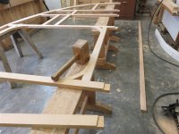
I worked my way around from front to aft doing all the joints in sequence, and eventually I had all the top done, all the verticals done, and the intermediate horizontal timbers which are for fixings for cupboards etc.
As you can see in the above photo, the next thing was to fit a horizontal along the bottom of the frames. More half-laps:

That was soon glued and pinned:

Those joints are blind, deliberately, because I don't want end grain exposed externally, and the under-edge of the frame is going to be exposed to water splashing up from the road. Well, almost. It will have a cover strip over it, fibreglassed, but should any water penetrate I wouldn't want it to find end-grain. It was a big moment detaching the frame from the pattern, involving a few goes through a mental checklist.
Time for some ply. As I said, I have bought poplar ply for this job, and I have been very impressed. However, there are some quirks. Firstly, it is 6.2mm x 1220 x 2500 in size. So, 1/4" x 4 feet by 2.5 meters......a weird (and typically British) mix of metric and imperial. Secondly, it's not square!

Ho hum. That just means careful checking on the bits where right angles are required. I clamped 2 sheets of 6mm together, and clamped the pattern on top:

After marking out, I found my most rarely used tool, the jigsaw, and cut out roughly:

The off cuts show the quality of the ply:

Yeah, it's not prime birch ply, but it weighs about half as much as birch, and is definitely not too shabby:

I then cut out the back ends:

Next, I did some very careful setting out, with the straight edge at the bottom being the reference from which everything is set out:

I then glued and pinned it in place:

.......and rough-cut the door. Not TOO roughly, as the offcut is a big piece of ply which I'd like to use later on:

Sorry, that photo is sideways. This is better:

But Mike, I hear you all cry, the ply doesn't reach the bottom of the frame!
Patience. All will become clear. Once the glue was dry, I went around with a flush trimmer, and produced the final shape for most of the wall:

My half-laps had worked OK:

The trimming went pretty well, but it's not my favourite thing. One slip of the screaming monster and you ruin both your template and the workpiece. I stood it out of the way to get on with the next thing:

I took some 150x19 nominal PAR (145 x 14) and thicknessed it down to 12mm thick. Out came the router again, this time with a winged cutter to do a rebate on the edge of the boards. Honestly, I hate the router, and have used it more in the last week than in the whole of the last year:


That rebate is the same depth as the ply.
As you can see in the above photo, the next thing was to fit a horizontal along the bottom of the frames. More half-laps:
That was soon glued and pinned:
Those joints are blind, deliberately, because I don't want end grain exposed externally, and the under-edge of the frame is going to be exposed to water splashing up from the road. Well, almost. It will have a cover strip over it, fibreglassed, but should any water penetrate I wouldn't want it to find end-grain. It was a big moment detaching the frame from the pattern, involving a few goes through a mental checklist.
Time for some ply. As I said, I have bought poplar ply for this job, and I have been very impressed. However, there are some quirks. Firstly, it is 6.2mm x 1220 x 2500 in size. So, 1/4" x 4 feet by 2.5 meters......a weird (and typically British) mix of metric and imperial. Secondly, it's not square!
Ho hum. That just means careful checking on the bits where right angles are required. I clamped 2 sheets of 6mm together, and clamped the pattern on top:
After marking out, I found my most rarely used tool, the jigsaw, and cut out roughly:
The off cuts show the quality of the ply:
Yeah, it's not prime birch ply, but it weighs about half as much as birch, and is definitely not too shabby:
I then cut out the back ends:
Next, I did some very careful setting out, with the straight edge at the bottom being the reference from which everything is set out:
I then glued and pinned it in place:
.......and rough-cut the door. Not TOO roughly, as the offcut is a big piece of ply which I'd like to use later on:
Sorry, that photo is sideways. This is better:
But Mike, I hear you all cry, the ply doesn't reach the bottom of the frame!
Patience. All will become clear. Once the glue was dry, I went around with a flush trimmer, and produced the final shape for most of the wall:
My half-laps had worked OK:
The trimming went pretty well, but it's not my favourite thing. One slip of the screaming monster and you ruin both your template and the workpiece. I stood it out of the way to get on with the next thing:
I took some 150x19 nominal PAR (145 x 14) and thicknessed it down to 12mm thick. Out came the router again, this time with a winged cutter to do a rebate on the edge of the boards. Honestly, I hate the router, and have used it more in the last week than in the whole of the last year:
That rebate is the same depth as the ply.
Attachments
Last edited:
Mike G
Petrified Pine
Here is the ply/ rebate posed photo:

Given the option of getting another cutter out for the router to do a round-over, or having a few peaceful minutes with a block plane, I set the bloody thing aside and walked the length of the boards a few times:

That rebate cover the bottom edge of the ply:

Before fixing it in place, I made very certain that the bottom edge was straight:


With the board clamped in it's final position, I took an offcut of the framing material, and marked out for the bottom edge of a joint on each of the vertical frame members:

The router didn't get to rest for too long. I fitted a guided trimming cutter, again, using the edge of the PAR as a guide, I formed the top edge of the joints:

With a tenon saw I then cut the other edge (after the board was removed), as well as cutting a couple of vertical cuts on the same:

This was as a result of being awake at 3.00 last night. You have to think about something.

The piece which will fit in that housing is going to be doing a lot of work, structurally, so removing any chance of it twisting or otherwise moving just seemed like a good idea. Next up, I fitted the edge of that board (4x1) into the housing, and marked it up:

Before housing out to those lines:

Two 9mm housings gave me 18mm of lap, and a really strong junction:

After rough-cutting the bottom of the door opening in the pine, it was time to glue that lot up:

I decided to use the 502 (non PU) for the top edge, where the board is rebated over the bottom edge of the ply, because I didn't want to be dealing with a heap of glue oozing out of the joint, which may or may not be on show in the finished item. The glue up went well:

I went off and did other things for a couple of hours, then came back and de-clamped. I pinned on the template for the lower edge of the door, and trimmed the PAR to shape. It MOSTLY went well. One bit will need some hand-work:


So, barring a couple of small jobs, that's the woodwork of one side finished for now:

Here's a fun little detail, which you'll have to remember for later, when this lot is fixed to the chassis:

Talking of the chassis, I'm expecting it this week. Exciting!
Given the option of getting another cutter out for the router to do a round-over, or having a few peaceful minutes with a block plane, I set the bloody thing aside and walked the length of the boards a few times:
That rebate cover the bottom edge of the ply:
Before fixing it in place, I made very certain that the bottom edge was straight:
With the board clamped in it's final position, I took an offcut of the framing material, and marked out for the bottom edge of a joint on each of the vertical frame members:
The router didn't get to rest for too long. I fitted a guided trimming cutter, again, using the edge of the PAR as a guide, I formed the top edge of the joints:
With a tenon saw I then cut the other edge (after the board was removed), as well as cutting a couple of vertical cuts on the same:
This was as a result of being awake at 3.00 last night. You have to think about something.
The piece which will fit in that housing is going to be doing a lot of work, structurally, so removing any chance of it twisting or otherwise moving just seemed like a good idea. Next up, I fitted the edge of that board (4x1) into the housing, and marked it up:
Before housing out to those lines:
Two 9mm housings gave me 18mm of lap, and a really strong junction:
After rough-cutting the bottom of the door opening in the pine, it was time to glue that lot up:
I decided to use the 502 (non PU) for the top edge, where the board is rebated over the bottom edge of the ply, because I didn't want to be dealing with a heap of glue oozing out of the joint, which may or may not be on show in the finished item. The glue up went well:
I went off and did other things for a couple of hours, then came back and de-clamped. I pinned on the template for the lower edge of the door, and trimmed the PAR to shape. It MOSTLY went well. One bit will need some hand-work:
So, barring a couple of small jobs, that's the woodwork of one side finished for now:
Here's a fun little detail, which you'll have to remember for later, when this lot is fixed to the chassis:
Talking of the chassis, I'm expecting it this week. Exciting!
Last edited:
HOJ
Sapling
SamQ aka Ah! Q!
Old Oak
Thirded. Great job, Mike.I'm not keen on just "liking" posts @Mike G this needs a positive acknowledgement, thanks for posting such an informative and detailed description of your project.
Mike, I'm getting the distinct impression that you aren't just making this up as you go along, but have a file full of drawings of every carefully thought- through detail!Here's a fun little detail, which you'll have to remember for later, when this lot is fixed to the chassis:
Mike G
Petrified Pine
You're not wrong. I've been drawing this for a couple of years, Andy. There are still some bits which are quite hard to visualise, and this is one of them. I hope I've got it right!Mike, I'm getting the distinct impression that you aren't just making this up as you go along, but have a file full of drawings of every carefully thought- through detail!
What's the ledge for?Here is the ply/ rebate posed photo:
View attachment 35178
Given the option of getting another cutter out for the router to do a round-over, or having a few peaceful minutes with a block plane, I set the bloody thing aside and walked the length of the boards a few times:
View attachment 35179
That rebate cover the bottom edge of the ply:
View attachment 35180
Before fixing it in place, I made very certain that the bottom edge was straight:
View attachment 35181
View attachment 35182
With the board clamped in it's final position, I took an offcut of the framing material, and marked out for the bottom edge of a joint on each of the vertical frame members:
View attachment 35183
The router didn't get to rest for too long. I fitted a guided trimming cutter, again, using the edge of the PAR as a guide, I formed the top edge of the joints:
View attachment 35184
With a tenon saw I then cut the other edge (after the board was removed), as well as cutting a couple of vertical cuts on the same:
View attachment 35185
This was as a result of being awake at 3.00 last night. You have to think about something.
View attachment 35186
The piece which will fit in that housing is going to be doing a lot of work, structurally, so removing any chance of it twisting or otherwise moving just seemed like a good idea. Next up, I fitted the edge of that board (4x1) into the housing, and marked it up:
View attachment 35187
Before housing out to those lines:
View attachment 35188
Two 9mm housings gave me 18mm of lap, and a really strong junction:
View attachment 35189
After rough-cutting the bottom of the door opening in the pine, it was time to glue that lot up:
View attachment 35190
I decided to use the 502 (non PU) for the top edge, where the board is rebated over the bottom edge of the ply, because I didn't want to be dealing with a heap of glue oozing out of the joint, which may or may not be on show in the finished item. The glue up went well:
View attachment 35191
I went off and did other things for a couple of hours, then came back and de-clamped. I pinned on the template for the lower edge of the door, and trimmed the PAR to shape. It MOSTLY went well. One bit will need some hand-work:
View attachment 35192
View attachment 35193
So, barring a couple of small jobs, that's the woodwork of one side finished for now:
View attachment 35194
Here's a fun little detail, which you'll have to remember for later, when this lot is fixed to the chassis:
View attachment 35195
Talking of the chassis, I'm expecting it this week. Exciting!
Is that the outside face?
It's certainly enigmatic!!
Mike G
Petrified Pine
What's the ledge for?
The ledge sits on top of the chassis, with the wall entirely covering the chassis. The "ledge" is in fact the outer member of the floor frame, and the wall will be bolted down to the chassis through it. It will also be bolted to the chassis horizontally through the lower piece of 2x1, below the "ledge".
Is that the outside face?
No, the ply is on the inside face. The outer face of the wall will be cedar strips.
duke
Old Oak
Wonderful progress Mike, your fine work is way above my pay scale. ")
Cabinetman
Sequoia
- Joined
- Oct 11, 2020
- Messages
- 5,372
- Reaction score
- 1,098
- Location
- Lincolnshire Wolds + Massachusetts
- Name
- Ian
It’s all fascinating Mike, and fairly obviously as you said there’s been a lot of planning gone into this, probably with a lot of revisions?
The little step in the floor edge member I think probably is where the kitchen wall goes up to?
The little step in the floor edge member I think probably is where the kitchen wall goes up to?
Mike G
Petrified Pine
It’s all fascinating Mike, and fairly obviously as you said there’s been a lot of planning gone into this, probably with a lot of revisions?
Although I've been drawing this for a long time, it wasn't until I actually had the parts from the trailer parts supplier here at home that I was able to finalise the drawings. That coincided with having a friend's commercially built teardrop here for repair, and being able to take one or two measurements, and also get the feel of the interior. That's when I added the 145mm PAR board under the ply, to get all that additional headroom........so the detail I have just built was only added in the last few weeks.
The little step in the floor edge member I think probably is where the kitchen wall goes up to?
It is. Therein lies a design detail I haven't seen on any other teardrop: the kitchen floor is lower than the bedroom floor, so this piece of timber will be under the floor in the bedroom, and above the floor in the kitchen.
Alasdair
Sapling
This is a facinating build Mike and carried out with the usual skill and attention to detail we have all come to expect from you. I look forward to following along with envy at the level of patience and craftmanship on display.
MattS
Nordic Pine
This looks like a lot of fun to build! Excellent craftmanship as ever.
You can tell Mike didn't work in caravan QC !!This looks like a lot of fun to build! Excellent craftmanship as ever.

And will be ready for the August bank holiday at this rateThis looks like a lot of fun to build! Excellent craftmanship as ever.
Mike G
Petrified Pine
As long as it is ready for spring next year I'll be happy.And will be ready for the August bank holiday at this rate
Mike G
Petrified Pine
I sneaked an hour or so in the workshop, and got it insulated:

The fly battens were to prevent the expanding foam of the PU glue from pushing the insulation upwards. It's critical that it stays flush with the timberwork. In some areas I did a tight fit, much more often, I left gaps to fill with foam:


The fly battens were to prevent the expanding foam of the PU glue from pushing the insulation upwards. It's critical that it stays flush with the timberwork. In some areas I did a tight fit, much more often, I left gaps to fill with foam:
Lons
Old Oak
You can tell Mike didn't work in caravan QC !!
+1
Certainly not ABI / Elddis et al back in the day when staples and screws ruled the roost.
")