
-
Hi all and welcome to TheWoodHaven2 brought into the 21st Century, kicking and screaming! We all have Alasdair to thank for the vast bulk of the heavy lifting to get us here, no more so than me because he's taken away a huge burden of responsibility from my shoulders and brought us to this new shiny home, with all your previous content (hopefully) still intact! Please peruse and feed back. There is still plenty to do, like changing the colour scheme, adding the banner graphic, tweaking the odd setting here and there so I have added a new thread in the 'Technical Issues, Bugs and Feature Requests' forum for you to add any issues you find, any missing settings or just anything you'd like to see added/removed from the feature set that Xenforo offers. We will get to everything over the coming weeks so please be patient, but add anything at all to the thread I mention above and we promise to get to them over the next few days/weeks/months. In the meantime, please enjoy!
You are using an out of date browser. It may not display this or other websites correctly.
You should upgrade or use an alternative browser.
You should upgrade or use an alternative browser.
4 panel door build WIP
- Thread starter 9fingers
- Start date


- Joined
- Jul 21, 2014
- Messages
- 10,414
- Reaction score
- 165
AndyT":3c8y9xi3 said:Bob, isn't there a risk of the wood catching fire when you work this fast?!
Andy, I thought I was taking it quite steady compared to the rate of updates on your bed mate! :lol:
Bob
NickM
Old Oak
This is going to be a lovely and strong door.
- Joined
- Jul 21, 2014
- Messages
- 10,414
- Reaction score
- 165
Thanks Nick. Way over engineered for a cupboard under the stairs really.NickM":1bc5w010 said:This is going to be a lovely and strong door.
I’ve never made much with m&t joinery and it’s a chance to try out and combine things I’ve picked up here and there and apply my unusual woodworking preferences to.
With luck there will be the odd wrinkle in there that might just help someone with their projects.
Bob

Phil
Old Oak
That is looking very good Bob.
Interesting the dado cutters. The 'mericans seem use them a lot and I recall reading somewhere that they are not the safest to use.
Interesting the dado cutters. The 'mericans seem use them a lot and I recall reading somewhere that they are not the safest to use.
- Joined
- Jul 21, 2014
- Messages
- 10,414
- Reaction score
- 165
I don't want to start a dado safety discussion but there is a very even handed discussion on the legality to using them from a UK POV from our very own SteveM here:-
https://www.youtube.com/watch?v=9KiRDUPdhDg
They must be used on a saw with the capacity to take them both in terms of power (you are potentially removing 8 times the wood in a single cut) and with a spindle long enough to allow the retaining nut to go on all the way with the stack fitted. Steve and I have the same saw which comes with a spindle extension supplied with the dado set which is a cunning ploy to allow the saw to be CE marked permitting sale in Europe and yet safely mount a full 25mm dado stack.
Use of dado set is down to individual choice but I find them very useful indeed for my wood "machining" approach to projects.
Bob
https://www.youtube.com/watch?v=9KiRDUPdhDg
They must be used on a saw with the capacity to take them both in terms of power (you are potentially removing 8 times the wood in a single cut) and with a spindle long enough to allow the retaining nut to go on all the way with the stack fitted. Steve and I have the same saw which comes with a spindle extension supplied with the dado set which is a cunning ploy to allow the saw to be CE marked permitting sale in Europe and yet safely mount a full 25mm dado stack.
Use of dado set is down to individual choice but I find them very useful indeed for my wood "machining" approach to projects.
Bob
Craig Salisbury
Nordic Pine
Cabinetman":3oblasub said:Yes, thank you, I look in on here more now than previously (The other place is now burnt toast as far as I’m concerned) and I am a little sad that sometimes there isn’t anything all day in the general woodwork section, and I’m probably more guilty than most, I haven’t made anything worth talking about for a little while now as life has got in the way. But we are talking about it, so it’s likely that things will change for the better. We do have Craig (soon) and Tim"s work to enliven us at the mo, so that’s good.
I have a project that has been going on for five years in between other jobs, that I will be bringing in as a work in progress, but probably in a years time.
Should I be showing what I’ve done up to now? And then adding to it in six months time? Or, as I prefer present the whole thing in one big splurge? From my own perspective I feel that if it’s too long between sections the effect is lost. Interesting topic though. Ian
Im not sure if this refers to me? if so im honored

My next post will be more involved, i'm not much of a writer to be honest. however i currently have bronchitis so it will be a week or so before i get the final boards for this project, and then its onto more machining and such
- Joined
- Jul 21, 2014
- Messages
- 10,414
- Reaction score
- 165
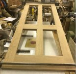
I snatched and hour or so in the workshop today and put all the parts together in a dry fit.
Pleased say that no adjustments were needed over and above a rubber headed persuader.
The diagonals were within 0.5 mm in 1987mm good enough for me :lol:
Panels next
Bob
Pleased say that no adjustments were needed over and above a rubber headed persuader.
The diagonals were within 0.5 mm in 1987mm good enough for me :lol:
Panels next
Bob
Cabinetman
Sequoia
- Joined
- Oct 11, 2020
- Messages
- 5,698
- Reaction score
- 1,386
- Location
- Lincolnshire Wolds + Massachusetts
- Name
- Ian
Yep it was you Craig, you be careful with the bronchitis, if you’re coughing up lots of green stuff see a doctor it could turn into pneumonia, friend of mine was only 35 and he ended up in hospital.
That door is looking excellent Bob, you’ll be able to get your number 4 plane out to flush it off next, lol.
That door is looking excellent Bob, you’ll be able to get your number 4 plane out to flush it off next, lol.
- Joined
- Jul 21, 2014
- Messages
- 10,414
- Reaction score
- 165
Panel time.
I'm using 9mm ply with oak construction veneers on both sides aiming to finish at a bit over 12mm after sanding to fit in the 1/2"grooves.
Here are a few pictures of my simple cross cutting jig - just a scrap of mdf with a piece of softwood screwed on.
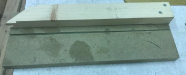
There is a small piece of veneer that spaces the pine off the mdf

The veneer to be cut is slid into the jig with the mark lined up with the kerf cut and held in place by pressing down on on the softwood guide.

Then run the small circular saw along the guide. The blade protrudes about 5mm and get a nice clean cut.

I used masking tape to indicate the pieces to be book matched, numbering each pair and marking the tape with an arrow.
I performed the rip cuts on the table saw with a fine tooth blade. I pride myself on having a very accurately set up saw and razor sharp blade and with moderate care I can rip the veneer edge to give a dead straight over nearly a 1m length.
There are other methods such as routing a pair at a time or heaven for-fend a hand plane but I find the table saw works for me.

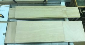
I ended up with 16 veneer leaves and 4 substrates ready for glue-up and vacuum pressing.
More to come soon
Bob
I'm using 9mm ply with oak construction veneers on both sides aiming to finish at a bit over 12mm after sanding to fit in the 1/2"grooves.
Here are a few pictures of my simple cross cutting jig - just a scrap of mdf with a piece of softwood screwed on.
There is a small piece of veneer that spaces the pine off the mdf
The veneer to be cut is slid into the jig with the mark lined up with the kerf cut and held in place by pressing down on on the softwood guide.
Then run the small circular saw along the guide. The blade protrudes about 5mm and get a nice clean cut.
I used masking tape to indicate the pieces to be book matched, numbering each pair and marking the tape with an arrow.
I performed the rip cuts on the table saw with a fine tooth blade. I pride myself on having a very accurately set up saw and razor sharp blade and with moderate care I can rip the veneer edge to give a dead straight over nearly a 1m length.
There are other methods such as routing a pair at a time or heaven for-fend a hand plane but I find the table saw works for me.
I ended up with 16 veneer leaves and 4 substrates ready for glue-up and vacuum pressing.
More to come soon
Bob
- Joined
- Jul 21, 2014
- Messages
- 10,414
- Reaction score
- 165
Time to tape up the pairs of leaves.
I find it best to use good quality masking tape that has a good stretch to it. I apply to one leaf, press down hard with a finger nail or even a roller and then stretching the tape as tight as I can, press it down on to the second leaf. Working from one end, I apply tape about every 200mm or so and then run a piece the full length of the join. This piece is more about keeping glue in the joint and does not have to be stretched taught just firmly pressed down.
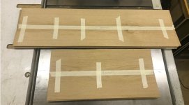
Not much to photo but here is the stack of taped pairs
When vacuum veneering you need a flat platen the everything gets pulled down onto. These panels are going into a frame so will be held flat by that but assembly is much easier if the panels are flat to start with.
I'm using some 1/2" birch ply which get a sand all over and rounded edges to make sure there is no risk of snagging the bag/ plastic sheet.
The platen only needs to be a little larger than the biggest panel.

Just to make sure any glue does not stick the precious veneer onto the platen, I tape newspaper on the top surface.

I make my vacuum bag from builders polythene sheet from Screwfix/Toolsatan. Essentially the sheet is cheap enough to be disposable but I re-use it for a few jobs and only discard it if it get punctured.
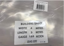
You need a piece twice the size of the platen plus about 6" extra all round for the seal.
Check the surface all over for any odd blemishes that might lead to a leak. I put a patch of insulation tape on any such blemishes - they are pretty rare.
It's at this stage where preparation is vital to prevent issues occurring once the glue is applied.
Lay the polythene onto a clean bench, use a clamp or similar to keep the vacuum pipe from slipping out and wrap a small piece of toweling around the end of the pipe to help the air to get out.


You will need glue and an application roller. cooking grade PVA will be fine, I does not have to be D4 just what I tend to have handy.

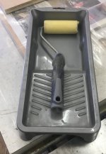
The seal is made with silicone sealant - cheapo is fine. Prepare the gun, poke out the previous cured silicone from the nozzle and make sure you have a spare cartridge handy so you don't run out part way through (like I did today!!)

Finally fire up the vacuum pump. mine has a calor gas bottle to act as reservoir which helps pull the vacuum quickly.
Time to draw breath, lock up the dog, ban the wife from interrupting and take the phone off the hook. You need to work quickly and accurately.
Bob
I find it best to use good quality masking tape that has a good stretch to it. I apply to one leaf, press down hard with a finger nail or even a roller and then stretching the tape as tight as I can, press it down on to the second leaf. Working from one end, I apply tape about every 200mm or so and then run a piece the full length of the join. This piece is more about keeping glue in the joint and does not have to be stretched taught just firmly pressed down.
Not much to photo but here is the stack of taped pairs
When vacuum veneering you need a flat platen the everything gets pulled down onto. These panels are going into a frame so will be held flat by that but assembly is much easier if the panels are flat to start with.
I'm using some 1/2" birch ply which get a sand all over and rounded edges to make sure there is no risk of snagging the bag/ plastic sheet.
The platen only needs to be a little larger than the biggest panel.
Just to make sure any glue does not stick the precious veneer onto the platen, I tape newspaper on the top surface.
I make my vacuum bag from builders polythene sheet from Screwfix/Toolsatan. Essentially the sheet is cheap enough to be disposable but I re-use it for a few jobs and only discard it if it get punctured.
You need a piece twice the size of the platen plus about 6" extra all round for the seal.
Check the surface all over for any odd blemishes that might lead to a leak. I put a patch of insulation tape on any such blemishes - they are pretty rare.
It's at this stage where preparation is vital to prevent issues occurring once the glue is applied.
Lay the polythene onto a clean bench, use a clamp or similar to keep the vacuum pipe from slipping out and wrap a small piece of toweling around the end of the pipe to help the air to get out.
You will need glue and an application roller. cooking grade PVA will be fine, I does not have to be D4 just what I tend to have handy.
The seal is made with silicone sealant - cheapo is fine. Prepare the gun, poke out the previous cured silicone from the nozzle and make sure you have a spare cartridge handy so you don't run out part way through (like I did today!!)
Finally fire up the vacuum pump. mine has a calor gas bottle to act as reservoir which helps pull the vacuum quickly.
Time to draw breath, lock up the dog, ban the wife from interrupting and take the phone off the hook. You need to work quickly and accurately.
Bob
Attachments

- Joined
- Jul 21, 2014
- Messages
- 10,414
- Reaction score
- 165
I forgot to add that if you are over a certain age, make sure you bladder is comfortable too! :lol:
Apply glue to back of the first veneer, open up the joint by folding and run a bead of glue the full length.

you cant really see the glue but roll on plenty - dont be mean
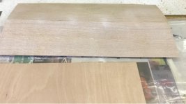
Next glue the first side of the substrate.

Lay the first leaf on and put tabs of tape along the long edges. Once glued there is a tendency for the veneer to slide and the tape keeps this under control.
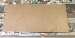
close up of the tabs

Glue the second leaf and substrate, fit the leaf and secure the tabs on the second side.

Now place the completed first panel onto the platen and add a second layer of newspaper.

Repeat the above steps to complete the second panel and place on the newspaper interleaving sheet.

to be continued...
Apply glue to back of the first veneer, open up the joint by folding and run a bead of glue the full length.
you cant really see the glue but roll on plenty - dont be mean
Next glue the first side of the substrate.
Lay the first leaf on and put tabs of tape along the long edges. Once glued there is a tendency for the veneer to slide and the tape keeps this under control.
close up of the tabs
Glue the second leaf and substrate, fit the leaf and secure the tabs on the second side.
Now place the completed first panel onto the platen and add a second layer of newspaper.
Repeat the above steps to complete the second panel and place on the newspaper interleaving sheet.
to be continued...
- Joined
- Jul 21, 2014
- Messages
- 10,414
- Reaction score
- 165
Now apply the silicone about 3" away from the platen edge.
A nice big blob around the pipe and then a generous bead all round 3 sides and end up with a nice blob at the end.
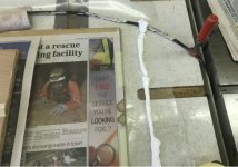
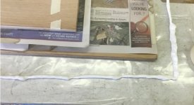


Fold over the top sheet (lid) of the polythene and gently press round the silicone bead so it touches the top sheet.

Open the tap on the vacuum pump and listen for any hissing and press down on the silicone to seal. Soon you will see the corners pulling down as the outside air pressure presses down on the panels.

If you get any leaks then either a bit more silicone or insulation tape (NOT both) will fix it.
Not that I'm doing two panels at one pressing. If you are doing this for the first time then I suggest just doing one at a time.
These panel went under vacuum about 2pm. I will possibly shut off the pump before I go to bed tonight.
People are sometime worried that the silicone will creep in and onto the job. This does not happen as on the vacuum side of the silicone the plastic sheets are press together by the outside air pressure. The silicone does not cure as it needs air/moisture for that to happen and that is excluded by the seal too.
When opened back up the silicone is still wet so just leave the top flipped back and overnight the silicone will cure and it can be peeled off cleanly ready to re-use the polythene for the next session.
Hope this is interesting. No need to use expensive vacuum bags
Thanks for reading this far.
Bob
A nice big blob around the pipe and then a generous bead all round 3 sides and end up with a nice blob at the end.
Fold over the top sheet (lid) of the polythene and gently press round the silicone bead so it touches the top sheet.
Open the tap on the vacuum pump and listen for any hissing and press down on the silicone to seal. Soon you will see the corners pulling down as the outside air pressure presses down on the panels.
If you get any leaks then either a bit more silicone or insulation tape (NOT both) will fix it.
Not that I'm doing two panels at one pressing. If you are doing this for the first time then I suggest just doing one at a time.
These panel went under vacuum about 2pm. I will possibly shut off the pump before I go to bed tonight.
People are sometime worried that the silicone will creep in and onto the job. This does not happen as on the vacuum side of the silicone the plastic sheets are press together by the outside air pressure. The silicone does not cure as it needs air/moisture for that to happen and that is excluded by the seal too.
When opened back up the silicone is still wet so just leave the top flipped back and overnight the silicone will cure and it can be peeled off cleanly ready to re-use the polythene for the next session.
Hope this is interesting. No need to use expensive vacuum bags
Thanks for reading this far.
Bob
Phil
Old Oak
To quote my friend "Nice"!
Cabinetman
Sequoia
- Joined
- Oct 11, 2020
- Messages
- 5,698
- Reaction score
- 1,386
- Location
- Lincolnshire Wolds + Massachusetts
- Name
- Ian
Thanks Bob, years, no, decades since I’ve done it but thank you that was most instructive. Ian
NickM
Old Oak
Interesting to see the veneering techniques.
- Joined
- Jul 21, 2014
- Messages
- 10,414
- Reaction score
- 165
Glad to hear it is of interest.NickM":2r162ek5 said:Interesting to see the veneering techniques.
I can't claim any originality of the methods I now use. Rob S of this parish did a veneering masterclass for a group of us at his place years ago Use Airpress equipment and Robert did a write up of the "lack of bag" bagging technique back in the days of THW1 together with some novel vacuum pump control methods.
Table saw preparation of the veneers is my contribution but may not be approval by all
First panels have now been sanded and a coat of finish to seal them and the larger panels will come out of the bag tonight.
Bob
- Joined
- Jul 21, 2014
- Messages
- 10,414
- Reaction score
- 165
Final few pics to cap off this veneering section.
One pair of panel fresh out of vacuum and taking their first breath of air.

Now with all the tape peeled off and a thorough sanding to thickness and a sealing coat of varnish.


Not sure what is happening with the colour there - they look much more similar in the flesh!
Just out of interest I connected up my inline power meter to the vacuum pump. Over the 9 hour period under vacuum, the pump ran for about 1hr 25min so was running about 10mins in each hour overcoming all leaks including in the pump itself. The motor was quite cool so no concerns there.
Next stage will be to trim off edges if needed and onto the glue up of the door.
Note to self: Must order some hinges.
Bob
One pair of panel fresh out of vacuum and taking their first breath of air.
Now with all the tape peeled off and a thorough sanding to thickness and a sealing coat of varnish.
Not sure what is happening with the colour there - they look much more similar in the flesh!
Just out of interest I connected up my inline power meter to the vacuum pump. Over the 9 hour period under vacuum, the pump ran for about 1hr 25min so was running about 10mins in each hour overcoming all leaks including in the pump itself. The motor was quite cool so no concerns there.
Next stage will be to trim off edges if needed and onto the glue up of the door.
Note to self: Must order some hinges.
Bob

chataigner
Old Oak
- Joined
- Jul 23, 2014
- Messages
- 1,127
- Reaction score
- 55
Terrific Bob, I did not realise that you could use sheet rather than bags and have avoided some larger jobs for lack of big enough bags. I will try this !
- Joined
- Jul 21, 2014
- Messages
- 10,414
- Reaction score
- 165
chataigner":2z0q3cpa said:Terrific Bob, I did not realise that you could use sheet rather than bags and have avoided some larger jobs for lack of big enough bags. I will try this !
Maybe try something modest size to start with to get a feel for the process. To be honest I think it is easier than a bag - saves struggling with the platen and the job pieces as they stay still and the polythene is wrapped around.
Bob

Really like the figuring on that darker looking panel Bob.
- Joined
- Jul 21, 2014
- Messages
- 10,414
- Reaction score
- 165
Yes I’ve picked out some more interesting sections of veneer for the outside faces. The rest is a bit bland but fine for the inside of the door when the eye should be distracted by the array of bottles in the cupboard.Andyp":31p7byem said:Really like the figuring on that darker looking panel Bob.
Bob

Rezi
New Shoots
Great WIP Bob. I don't have a veneering vacuum kit but that's an excellent tip using plastic sheets and silicon.
- Joined
- Jul 21, 2014
- Messages
- 10,414
- Reaction score
- 165
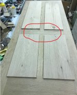
Prior to glue up I invited SWMBO into the workshop to confirm my choice of orientation of the panels.
This is what we decided together with some coloured dots fitted to make it easier during the glue up.
Here we are with glue and clamps fitted.

Do you think you spotted an error??
No with a glue up like this with 10 joints and panels to glue in, I like to do it is stages. I'm not in a hurry and what to keep the CUF out of the workshop.
I prefer to only glue a few joints at a time but dry fit the rest to ensure everything fits later on.
Here I've glued the rails and mullions only at the first step.
After a couple of hours, I knocked off one stile test fitted two panels, refitted the stile to check all was good then applied glue.

After dinner I did the final stile and panels knowing that I would not get much workshop time today after taking SWMBO to routine hospital appointments.
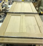
There might be a bit of a gap now and not only do I have decide on the moulding profile I want but also designing the jigs to make them safely as at least some of the process will be on the spindle moulder that needs maximum respect.
Catch you later
Bob
This is what we decided together with some coloured dots fitted to make it easier during the glue up.
Here we are with glue and clamps fitted.
Do you think you spotted an error??
No with a glue up like this with 10 joints and panels to glue in, I like to do it is stages. I'm not in a hurry and what to keep the CUF out of the workshop.
I prefer to only glue a few joints at a time but dry fit the rest to ensure everything fits later on.
Here I've glued the rails and mullions only at the first step.
After a couple of hours, I knocked off one stile test fitted two panels, refitted the stile to check all was good then applied glue.
After dinner I did the final stile and panels knowing that I would not get much workshop time today after taking SWMBO to routine hospital appointments.
There might be a bit of a gap now and not only do I have decide on the moulding profile I want but also designing the jigs to make them safely as at least some of the process will be on the spindle moulder that needs maximum respect.
Catch you later
Bob
Cabinetman
Sequoia
- Joined
- Oct 11, 2020
- Messages
- 5,698
- Reaction score
- 1,386
- Location
- Lincolnshire Wolds + Massachusetts
- Name
- Ian
It’s looking very good Bob, re-the mouldings would it be possible to cut two at once back to back and then split them? Just a thought it might be safer, the only other way as far as I can think is another fence with a strip of wood that matches the rebate on the underside of the moulding, which the wood can run along (after its had its rebate cut) in effect you would have two fences the one you normally run along and another one further out, so that you push the wood between them. Ian
- Joined
- Jul 21, 2014
- Messages
- 10,414
- Reaction score
- 165
Cabinetman":2ysnzldq said:It’s looking very good Bob, re-the mouldings would it be possible to cut two at once back to back and then split them? Just a thought it might be safer, the only other way as far as I can think is another fence with a strip of wood that matches the rebate on the underside of the moulding, which the wood can run along (after its had its rebate cut) in effect you would have two fences the one you normally run along and another one further out, so that you push the wood between them. Ian
Thanks Ian, I was thinking along similar sorts of lines by possibly making a finger board with a complementary moulding on it. I think a lot will depend on the order of doing the cuts to make sure I have enough support left as each stage.
Thanks for your interest Ian. Much appreciated.
Bob

A method some hand tool workers use for mouldings is to plane them along the edge of a wide board, then rip saw them off. The wide board being much easier to hold in place than a thin, bendy moulding. I am in no way qualified to suggest how to use a spindle moulder, but I wonder if that might be a transferable technique?
- Joined
- Jul 21, 2014
- Messages
- 10,414
- Reaction score
- 165
AndyT":36w713bc said:A method some hand tool workers use for mouldings is to plane them along the edge of a wide board, then rip saw them off. The wide board being much easier to hold in place than a thin, bendy moulding. I am in no way qualified to suggest how to use a spindle moulder, but I wonder if that might be a transferable technique?
Thanks Andy, that works very well for simple mouldings done in a single pass. this one is heading for needing three passes which will be interesting. I'll be counting fingers out and back in again at the end.
Bob
9fingers":1pr52428 said:I'll be counting fingers out and back in again at the end.
Bob
Yes, please be careful. We’ve all got used to your current moniker.
- Joined
- Jul 21, 2014
- Messages
- 10,414
- Reaction score
- 165
Not had much time for progress on this lately but I've decided on the moulding that I meed to make.

This is based on the paneling that is fitted near the door so should tie in nicely.
This is a rough mock up of how it integrates with the door panel.

I have a spindle moulder cutter that is part of a door set to create the profile out lined in white.

I've had a couple of snags. I want to cut the profile with the mounding on the top because if I did profile down, the second pass would leave a very narrow flat surface and not at all safe.
However this means the cutter has to be on top and needs to run the spindle anti clockwise.
First delay was to reprogramme the inverter and fit a switch to govern the direction.
Next, when running a test piece and a problem started with the bearings on an intermediate shaft between motor and the spindle and things went downhill from there!
Its all in pieces at the moment so I'll take a photo when it is rebuilt and ready to go. Most of the new parts have been machined just waiting for some bearings from Ebay.
That's it for now folks
Bob
This is based on the paneling that is fitted near the door so should tie in nicely.
This is a rough mock up of how it integrates with the door panel.
I have a spindle moulder cutter that is part of a door set to create the profile out lined in white.
I've had a couple of snags. I want to cut the profile with the mounding on the top because if I did profile down, the second pass would leave a very narrow flat surface and not at all safe.
However this means the cutter has to be on top and needs to run the spindle anti clockwise.
First delay was to reprogramme the inverter and fit a switch to govern the direction.
Next, when running a test piece and a problem started with the bearings on an intermediate shaft between motor and the spindle and things went downhill from there!
Its all in pieces at the moment so I'll take a photo when it is rebuilt and ready to go. Most of the new parts have been machined just waiting for some bearings from Ebay.
That's it for now folks
Bob
Cabinetman
Sequoia
- Joined
- Oct 11, 2020
- Messages
- 5,698
- Reaction score
- 1,386
- Location
- Lincolnshire Wolds + Massachusetts
- Name
- Ian
"I've had a couple of snags. I want to cut the profile with the mounding on the top because if I did profile down, the second pass would leave a very narrow flat surface and not at all safe.
However this means the cutter has to be on top and needs to run the spindle anti clockwise.
First delay was to reprogramme the inverter and fit a switch to govern the direction".
I must say Bob I didn’t really follow this sorry, not sure how the cutter is configured, when you put the wood through is it flat on the bed or vertical against a secondary fence?
I never been able or needed, to reverse direction on the moulder but it’s obviously caused problems, can’t really see why it will help. Ian
Ps, would it not be possible to make it out of a thicker piece of wood to start with and then cut a rebate?
However this means the cutter has to be on top and needs to run the spindle anti clockwise.
First delay was to reprogramme the inverter and fit a switch to govern the direction".
I must say Bob I didn’t really follow this sorry, not sure how the cutter is configured, when you put the wood through is it flat on the bed or vertical against a secondary fence?
I never been able or needed, to reverse direction on the moulder but it’s obviously caused problems, can’t really see why it will help. Ian
Ps, would it not be possible to make it out of a thicker piece of wood to start with and then cut a rebate?
- Joined
- Jul 21, 2014
- Messages
- 10,414
- Reaction score
- 165
BothCabinetman":kxqg9pyz said:I must say Bob I didn’t really follow this sorry, not sure how the cutter is configured, when you put the wood through is it flat on the bed or vertical against a secondary fence?
Cabinetman":kxqg9pyz said:I never been able or needed, to reverse direction on the moulder but it’s obviously caused problems, can’t really see why it will help. Ian
Ps, would it not be possible to make it out of a thicker piece of wood to start with and then cut a rebate?
Reversing did not cause the second problem
When I have the machine back together, I can take more photos to make it clear. apologies for not being able to describe it for you.
Bob
- Joined
- Jul 21, 2014
- Messages
- 10,414
- Reaction score
- 165
My ebay supplier came up trumps with the bearings I'd ordered arriving today.
So this afternoon I was out in the metalwork shop making the new idlers.
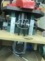
This is the view at the back of the spindle moulder with the covers off. The new idlers are in the white ring. Their purpose is to change the direction on the drive belt where it drives the spindle which is deep in the works and not visible. The motor at the bottom drives the belt, round one idler, round the end of the spindle , back over the other idler back to the motor.
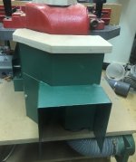
The belt is running at around 1km per minute and like the rest of the spindle moulder will not take any prisoners so the belt and idlers are hidden away behind guards. At the bottom right of the photo you can see the waste extraction spigot.
This is the new reversing switch added on the side of the stop/start switch box.

The switch sends a low voltage signal to the inverter that controls the motor itself. When running in reverse, the display shows a minus sign in front of the frequency display.
Forward

Reverse

One huge advantage of inverter control is that I did not have to use critical size pulleys for the drive just something out of the scrap box and adjust the inverter to get the correct speed.
hence the 53.8 Hz instead of being stuck with 50Hz.
The machine is all back together now.
In the next installment I'll try and sort out Ian's query about the cutter and why it has to be run clockwise.
Bob
So this afternoon I was out in the metalwork shop making the new idlers.
This is the view at the back of the spindle moulder with the covers off. The new idlers are in the white ring. Their purpose is to change the direction on the drive belt where it drives the spindle which is deep in the works and not visible. The motor at the bottom drives the belt, round one idler, round the end of the spindle , back over the other idler back to the motor.
The belt is running at around 1km per minute and like the rest of the spindle moulder will not take any prisoners so the belt and idlers are hidden away behind guards. At the bottom right of the photo you can see the waste extraction spigot.
This is the new reversing switch added on the side of the stop/start switch box.
The switch sends a low voltage signal to the inverter that controls the motor itself. When running in reverse, the display shows a minus sign in front of the frequency display.
Forward
Reverse
One huge advantage of inverter control is that I did not have to use critical size pulleys for the drive just something out of the scrap box and adjust the inverter to get the correct speed.
hence the 53.8 Hz instead of being stuck with 50Hz.
The machine is all back together now.
In the next installment I'll try and sort out Ian's query about the cutter and why it has to be run clockwise.
Bob
- Joined
- Jul 21, 2014
- Messages
- 10,414
- Reaction score
- 165
The cutter I'm using for the moulding is part of a rail and stile door set. In normal use it is used profile up and run the spindle in the standard direction of anticlockwise and feeding from the right.
This would need the profile to run on the table this way up
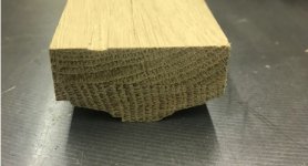
This might be ok for the first pass but on the second pass the area in contact with the table is very narrow ~10mm and can easily tip.
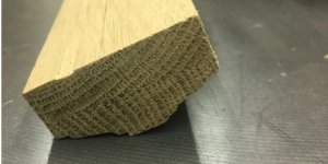
Far too easy to lose control and ruin the job.
So the intention is to reference the cut to the back face like this.

So as a result the cutter has to be flipped over, run clockwise and feed from the left.
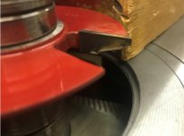

Guards removed for clarity.
the first cut is run like this
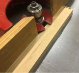
With the guards fitted, springs push the work towards the fence and down onto the table. Also you can't see what is happening! but the big bonus is your pinkies are kept well out of the way.

The second pass is simply down by flipping the workpiece end for end and not photoed.
I started off with this pile.
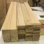
50 minutes later I had this pile.
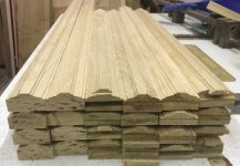
Next installment will be to cut the rebates safely using the table saw and a feather board.
Bob
This would need the profile to run on the table this way up
This might be ok for the first pass but on the second pass the area in contact with the table is very narrow ~10mm and can easily tip.
Far too easy to lose control and ruin the job.
So the intention is to reference the cut to the back face like this.
So as a result the cutter has to be flipped over, run clockwise and feed from the left.
Guards removed for clarity.
the first cut is run like this
With the guards fitted, springs push the work towards the fence and down onto the table. Also you can't see what is happening! but the big bonus is your pinkies are kept well out of the way.
The second pass is simply down by flipping the workpiece end for end and not photoed.
I started off with this pile.
50 minutes later I had this pile.
Next installment will be to cut the rebates safely using the table saw and a feather board.
Bob
Cabinetman
Sequoia
- Joined
- Oct 11, 2020
- Messages
- 5,698
- Reaction score
- 1,386
- Location
- Lincolnshire Wolds + Massachusetts
- Name
- Ian
Yes now I understand, I can put a plywood extra long table on mine when needed, so it’s easy to screw bits to, to enable me to get round problems like that, just strips of wood so that when the work has passed the cutter it rests on the strip and can’t fall, and another strip on the side already cut then the downward spring can bear on it. But well done they look good, not sure if I would cut the rebates on the saw or the moulder but the result will be the same.
That door will suddenly come alive when you fit those to it – happy days. Ian
That door will suddenly come alive when you fit those to it – happy days. Ian
Great to see that the plan worked well.
- Joined
- Jul 21, 2014
- Messages
- 10,414
- Reaction score
- 165
Now for the rebating. I could do this on the spindle but I don't have a fancy rebate block with scribes etc and one of my cuts is within 3mm or so of the decrative profiles so I'm option to do this on the table saw in two cuts each with a feather board to minimise kickback risk and also hopefully to instill some confidence to others wanting to make rebates and without access to a spindle.

As with the profiling I'm using the base of the moulding against the fence and the feather board is raised by some 18mm scrap mdf to that the fingers and press on the central flat section. This prevents any rotational twist along the axis of the workpiece.
Here is is in close up.

and with the feather board doing its stuff.

OK there is no crown guard over the blade but with the featherboad in place and a push stick, you going to have to try hard to get your fingers in contact with the blade.

First cut complete, rinse and repeat with the rest of them.
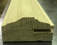
The second cut has the back of the moulding down onto the table. With the blade height reduced to 12mm and the featherboard spacer removed, the stock is pressed against the fence on the narrower side but still plenty of support on the infeed side.


On the way in
View attachment 2
and out
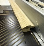
A little care is needed with the push stick at the end of the cut to apply pressure downwards and to the left to prevent any tendency for the job to tip. For those of you who favour longer push sticks, two can be handy one for the feed and ond as a guide. With my push stick design, I'm closer to the blade but with wrist pressure can combimne guiding and feeding with one hand.
As always with table saw work, standing slightly to one side of the line of the blade is important.
After repeating for all 24 lengths the moulding are complete. The irregular shape now means they did not cooperate to give a tidy pile for the photo.

Just a case now of a light sand and a critical examination of the product to choose the absolute best for fitting to the areas immediate eye line and a bit of grain matching whilst relegating any parts with issues to the lower and inner faces of the door.
I've made no spares this time so even more "measure twice cut once" strategy to the fore in the next steps
I'm sure you all have your ways of cutting mitres so I'll not labour this point save to say I will be cutting to final size on the table saw or mitresaw and none of that 45 degree shooting board nonsense in my shop :lol:
Thanks for getting this far with me.
Bob
As with the profiling I'm using the base of the moulding against the fence and the feather board is raised by some 18mm scrap mdf to that the fingers and press on the central flat section. This prevents any rotational twist along the axis of the workpiece.
Here is is in close up.
and with the feather board doing its stuff.
OK there is no crown guard over the blade but with the featherboad in place and a push stick, you going to have to try hard to get your fingers in contact with the blade.
First cut complete, rinse and repeat with the rest of them.
The second cut has the back of the moulding down onto the table. With the blade height reduced to 12mm and the featherboard spacer removed, the stock is pressed against the fence on the narrower side but still plenty of support on the infeed side.
On the way in
View attachment 2
and out
A little care is needed with the push stick at the end of the cut to apply pressure downwards and to the left to prevent any tendency for the job to tip. For those of you who favour longer push sticks, two can be handy one for the feed and ond as a guide. With my push stick design, I'm closer to the blade but with wrist pressure can combimne guiding and feeding with one hand.
As always with table saw work, standing slightly to one side of the line of the blade is important.
After repeating for all 24 lengths the moulding are complete. The irregular shape now means they did not cooperate to give a tidy pile for the photo.
Just a case now of a light sand and a critical examination of the product to choose the absolute best for fitting to the areas immediate eye line and a bit of grain matching whilst relegating any parts with issues to the lower and inner faces of the door.
I've made no spares this time so even more "measure twice cut once" strategy to the fore in the next steps
I'm sure you all have your ways of cutting mitres so I'll not labour this point save to say I will be cutting to final size on the table saw or mitresaw and none of that 45 degree shooting board nonsense in my shop :lol:
Thanks for getting this far with me.
Bob
Phil
Old Oak
Looking very good 