Dr.Al
Old Oak
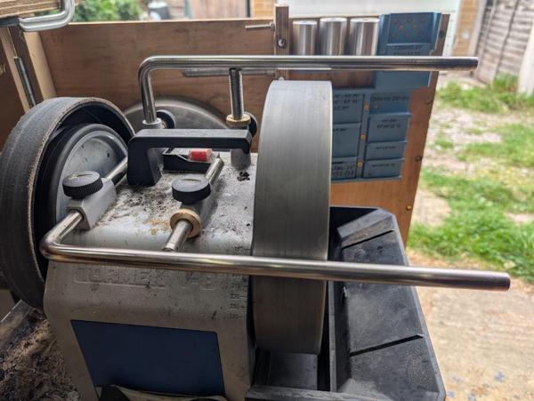
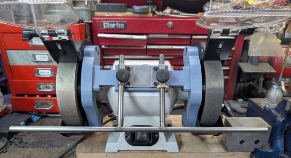
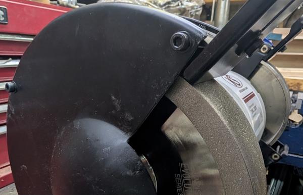
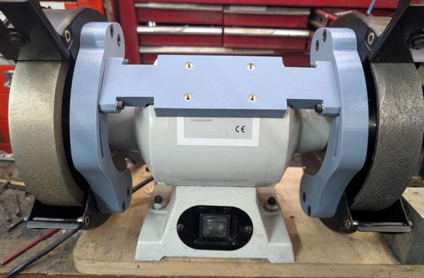
I've decided to make a few upgrades to one of my bench grinders. This is a "before" photo of the grinder:
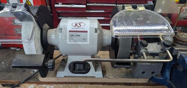
It's a fantastic machine, a 200 mm diameter medium speed (1450 rpm) grinder that came with an 80 grit CBN wheel (on the right) and a 180 grit aluminium oxide grinding wheel on the left. The provided tool rests (one of which you can see on the left) are much better quality than on any of my other grinders, but I replaced the right one with a Tormek BGM (Bench Grinder Mount) as it's nice to be able to use the Tormek jigs with the bench grinder.
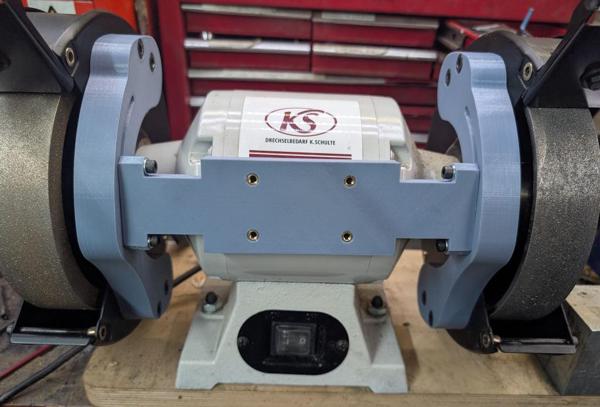
Since doing that, I rarely use the actual Tormek except for turning tools (for hand tools I follow the course CBN grind with bench stones). Given that both Richard Raffan and Keith Rowley consider a 180 grit wheel plenty good enough for turning tools, my plan is to use the left-hand wheel for turning tools at which point the Tormek will be used even less often.
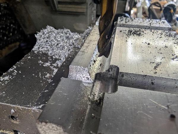
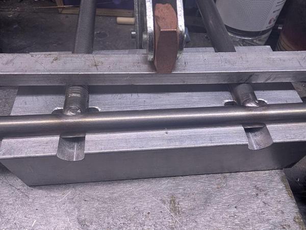
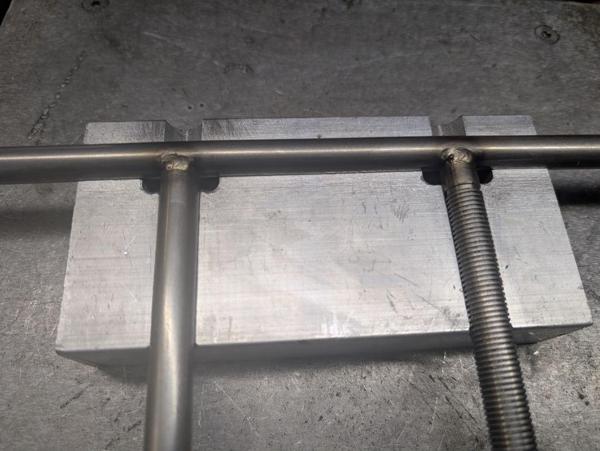
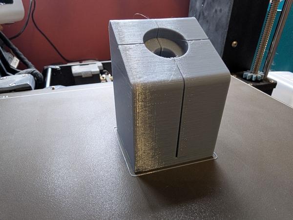
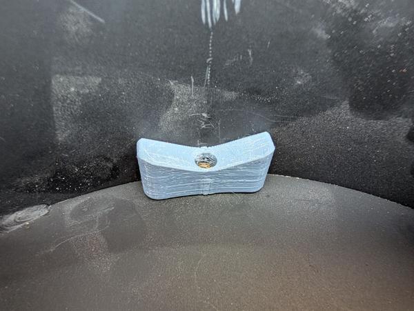
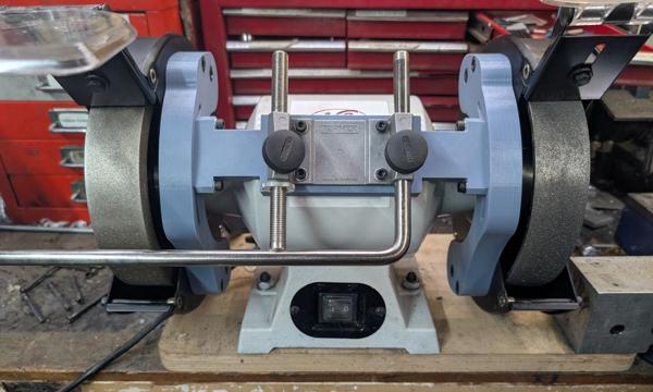
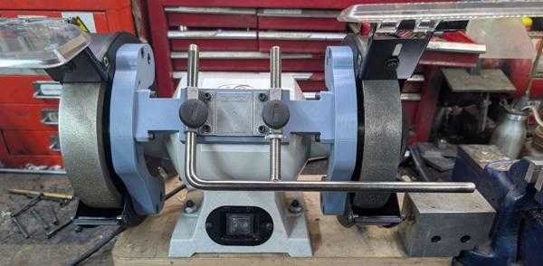
The bench grinder is bolted to a bit of thick plywood , which in turn is held down to the bench with some big thumbscrews. That means I can move the grinder to another area of the workshop if I need to, although I rarely do so. The location it is currently in is a bit of tight squeeze. It's as far over to the left as it can be while still allowing the drawers of the red Bisley unit to open. The BGM mount on the right-hand side had to have a bit milled out of a block of aluminium to go over the top of the bench vice mount:
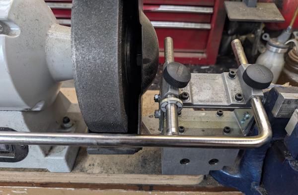
It also gets in the way of the bench vice a bit, so I often have to remove the Tormek bar in order to work on stuff in the vice.
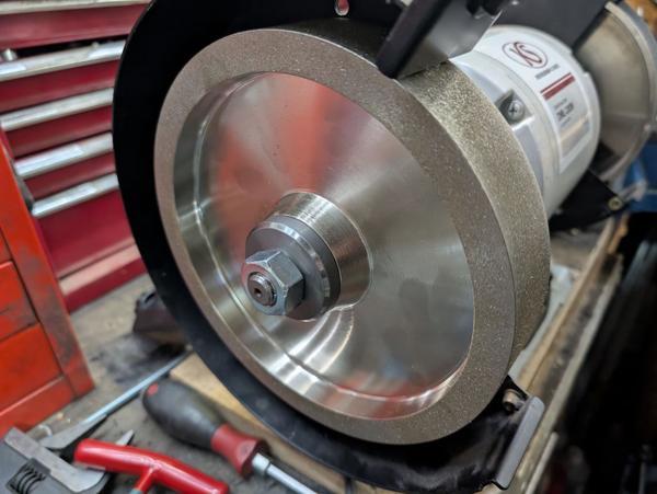
The thing that spurred me on to give this already fantastic machine a bit of an upgrade was being offered a relatively cheap (but still quite pricey) deal on this 180 grit CBN wheel:
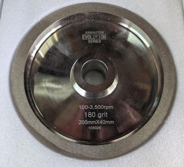
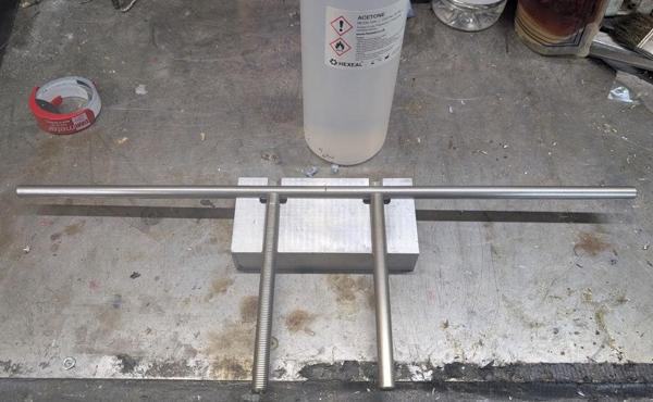
It's 200 mm diameter and 40 mm wide, so the perfect size for the medium-speed grinder. The bore, however, is 31.75 mm (1¼" in antediluvian units), whereas the shaft on the grinder is 15.85 mm (just under 5/8"). Thus, some new bushes were required. I did a bit of skip-diving and found these off-cuts of stainless steel of some sort:
They're about 63.5 mm (2½") diameter, which is a lot bigger than what I need, but that's fine. They're about 16 mm long (ignoring the milled big sticking out), which should do fine.
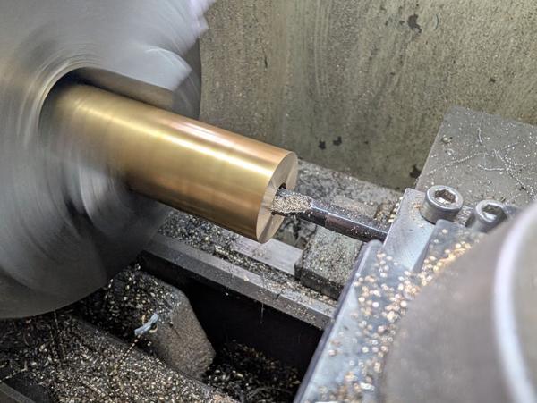
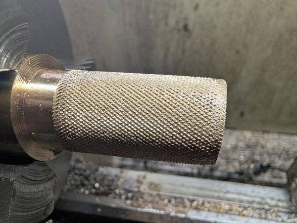
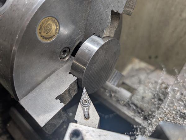
The first job was to hold them in the chuck and use a carbide tool that I only use for roughing jobs like this (as it leaves a pretty rough finish):
It wasn't looking too bad straight off that tool...
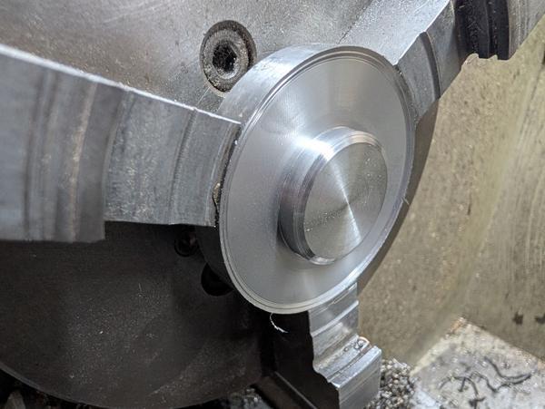
... but I gave it a clean up pass with a sharper carbide tool anyway:
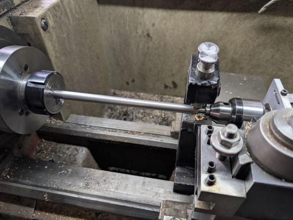
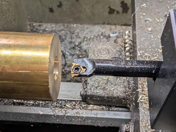
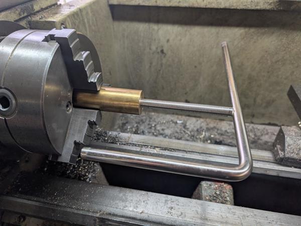
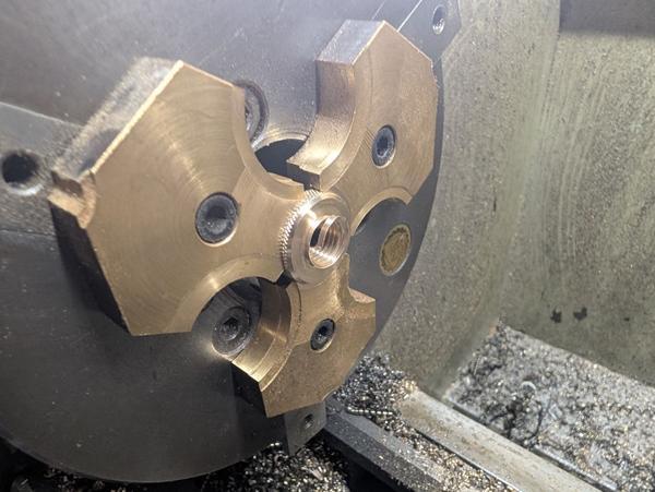
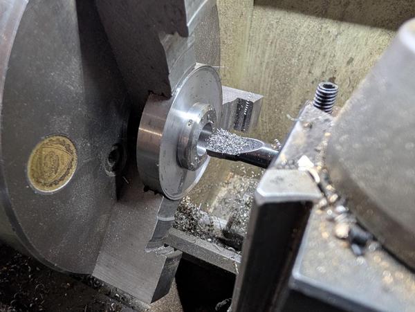
Each piece then got mounted in the outside jaws and I used a pointy tool to get inside the outer jaws so I could turn the smaller diameter:
I didn't go all the way into the face at the outer diameter (so I didn't risk hitting the jaws). The outer diameter was going to get reduced later so it seemed safest to just leave it like that for now.
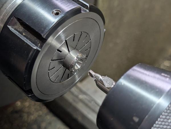
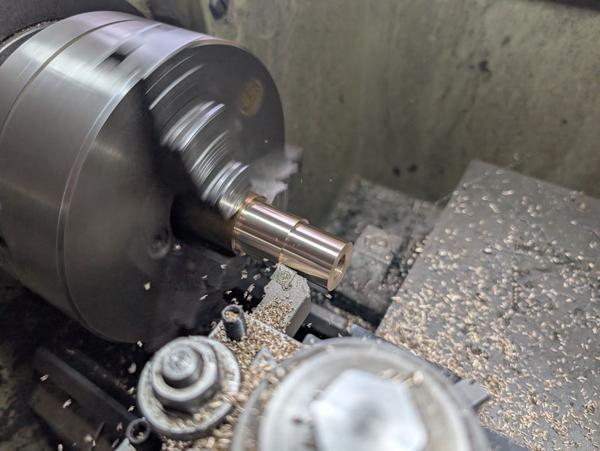
After shaping that 31.75 mm diameter bit (and checking it was a good fit in the CBN wheel, which I could offer up to the lathe), I spot drilled, drilled 6 mm, 10 mm and 13 mm and then bored the hole out to 15.88 mm:
I had no way of checking that bore size without removing the part from the lathe, but I was feeling confident in my measurements, so I took it out of the chuck and offered it up to the grinder and thankfully it was a lovely fit.
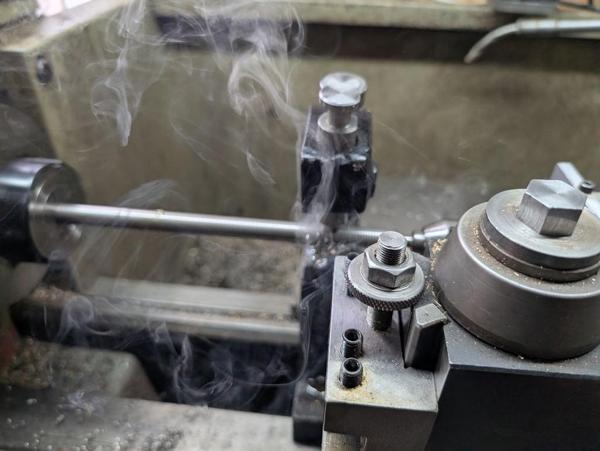
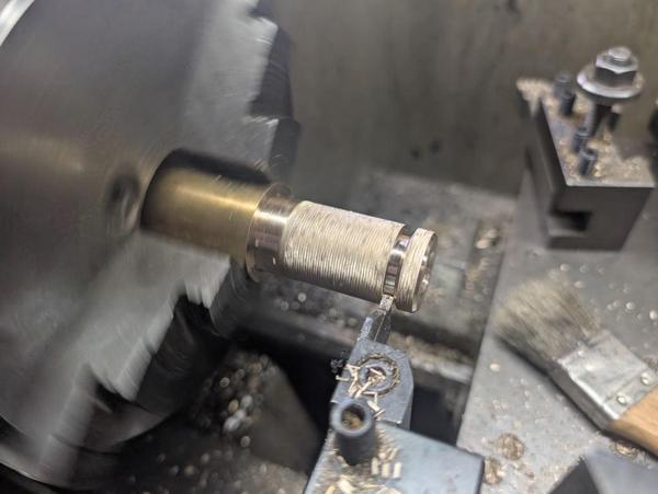
After getting both parts to the same stage, they got put back in the normal chuck jaws and the outside diameter reduced to 50 mm:
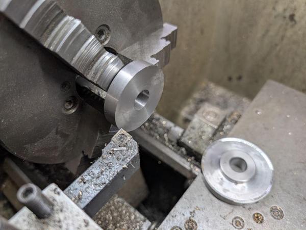
After a bit of chamfering and tidy-up, I was left with two finished bushes:
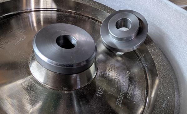
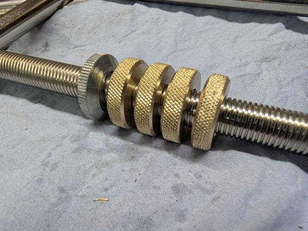
I was very happy to see that everything fitted perfectly:
To be continued...
It's a fantastic machine, a 200 mm diameter medium speed (1450 rpm) grinder that came with an 80 grit CBN wheel (on the right) and a 180 grit aluminium oxide grinding wheel on the left. The provided tool rests (one of which you can see on the left) are much better quality than on any of my other grinders, but I replaced the right one with a Tormek BGM (Bench Grinder Mount) as it's nice to be able to use the Tormek jigs with the bench grinder.
Since doing that, I rarely use the actual Tormek except for turning tools (for hand tools I follow the course CBN grind with bench stones). Given that both Richard Raffan and Keith Rowley consider a 180 grit wheel plenty good enough for turning tools, my plan is to use the left-hand wheel for turning tools at which point the Tormek will be used even less often.
The bench grinder is bolted to a bit of thick plywood , which in turn is held down to the bench with some big thumbscrews. That means I can move the grinder to another area of the workshop if I need to, although I rarely do so. The location it is currently in is a bit of tight squeeze. It's as far over to the left as it can be while still allowing the drawers of the red Bisley unit to open. The BGM mount on the right-hand side had to have a bit milled out of a block of aluminium to go over the top of the bench vice mount:
It also gets in the way of the bench vice a bit, so I often have to remove the Tormek bar in order to work on stuff in the vice.
The thing that spurred me on to give this already fantastic machine a bit of an upgrade was being offered a relatively cheap (but still quite pricey) deal on this 180 grit CBN wheel:
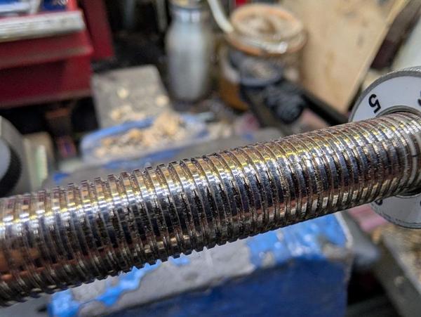
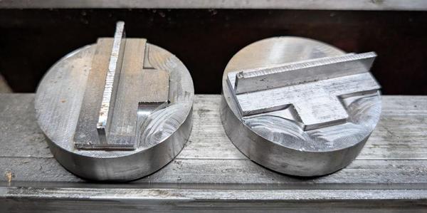
It's 200 mm diameter and 40 mm wide, so the perfect size for the medium-speed grinder. The bore, however, is 31.75 mm (1¼" in antediluvian units), whereas the shaft on the grinder is 15.85 mm (just under 5/8"). Thus, some new bushes were required. I did a bit of skip-diving and found these off-cuts of stainless steel of some sort:
They're about 63.5 mm (2½") diameter, which is a lot bigger than what I need, but that's fine. They're about 16 mm long (ignoring the milled big sticking out), which should do fine.
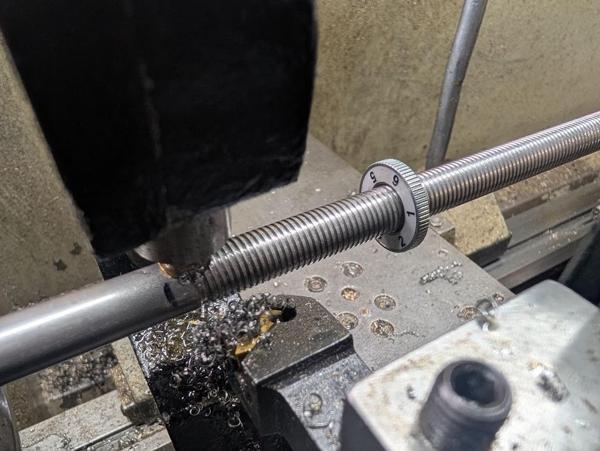
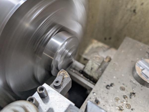
The first job was to hold them in the chuck and use a carbide tool that I only use for roughing jobs like this (as it leaves a pretty rough finish):
It wasn't looking too bad straight off that tool...
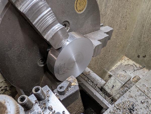
... but I gave it a clean up pass with a sharper carbide tool anyway:
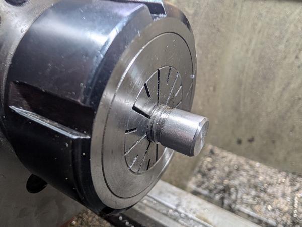
Each piece then got mounted in the outside jaws and I used a pointy tool to get inside the outer jaws so I could turn the smaller diameter:
I didn't go all the way into the face at the outer diameter (so I didn't risk hitting the jaws). The outer diameter was going to get reduced later so it seemed safest to just leave it like that for now.
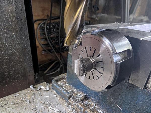
After shaping that 31.75 mm diameter bit (and checking it was a good fit in the CBN wheel, which I could offer up to the lathe), I spot drilled, drilled 6 mm, 10 mm and 13 mm and then bored the hole out to 15.88 mm:
I had no way of checking that bore size without removing the part from the lathe, but I was feeling confident in my measurements, so I took it out of the chuck and offered it up to the grinder and thankfully it was a lovely fit.
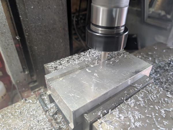
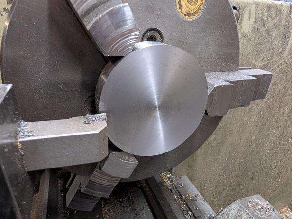
After getting both parts to the same stage, they got put back in the normal chuck jaws and the outside diameter reduced to 50 mm:
After a bit of chamfering and tidy-up, I was left with two finished bushes:
I was very happy to see that everything fitted perfectly:
To be continued...
")