• Hi all and welcome to TheWoodHaven2 brought into the 21st Century, kicking and screaming! We all have Alasdair to thank for the vast bulk of the heavy lifting to get us here, no more so than me because he's taken away a huge burden of responsibility from my shoulders and brought us to this new shiny home, with all your previous content (hopefully) still intact! Please peruse and feed back. There is still plenty to do, like changing the colour scheme, adding the banner graphic, tweaking the odd setting here and there so I have added a new thread in the 'Technical Issues, Bugs and Feature Requests' forum for you to add any issues you find, any missing settings or just anything you'd like to see added/removed from the feature set that Xenforo offers. We will get to everything over the coming weeks so please be patient, but add anything at all to the thread I mention above and we promise to get to them over the next few days/weeks/months. In the meantime, please enjoy!

A Japanese style garden shed

GaryR

Nordic Pine
Joined
Jan 22, 2024
Messages
706
Reaction score
1,288
Location
Bloomington, Indiana, USA
Name
Gary
This may take a while. I've been working on this project for over three years. But I'm new here so I have to get you all caught up.

In the summer of 2020, dear wife asked me about getting a garden shed so that she could move her gardening tools and pots and what-not out of what she laughingly thought of as our garage and I more reasonably recognized as my woodworking shop. "Do you think we can buy one? Or maybe can you build one?," she said.

I am not a carpenter but I am a cheapskate so of course I said, "Sure, I can build one. Let me think about it."

Then I realized that this was my opportunity to take my interest in Japanese joinery to another level.

I came back to my wife with a proposal: "I will build you a garden shed, but only if I can over do it."

We have been married long enough that we both knew how this would play out. So she rolled her eyes and said, "OK. Build what you want. We will pay for a minimal shed. But you are going to pay for anything extra."

"Deal!" I said.
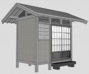
 
Our priorities for the shed were:

Store garden tools. Japanese timber frame methods, joinery, and aesthetic. Local materials where possible. Low maintenance. Natural and recyclable materials like wood, metal, stone, earth. Fit the climate and site (Pacific Northwest of the USA).

After a few months of design and redesign and re-redesign, here is the shed in Sketchup.

958AC0EB-E0EF-4064-B4D0-E5802090FC28_1_105_c.jpeg

It is small. The foundation in plan is 9 feet by 6 feet. Sorry about the imperial measurement but I'm in the US and roofing materials are all in that measurement. On the other hand, it is very close to the classic shaku system of measurement in Japan. And the proportions are close to the classic modular system for residential architecture in Japan based on the dimensions of a tatami mat.

Also, the small size fits our site and is below the minimum dimensions that require building permits and city inspections. That means that according to local regulations I can build whatever I want however I want.

Those considerations defined the plan dimensions. After that I have converted and done all my measurements and dimensions in metric. The posts, for example, are 120 x 120 mm.

After deciding on the frame dimensions and basic design I ordered the post and beam timbers. I decided to use a wood most commonly called around here Port Orford cedar, but also known as Lawson's cypress. Botanically it is has undergone revisions but now known as Chamaecyparis lawsoniania.. It grows in a narrow strip along the North American coast from northern California to British Columbia. It is extremely rot resistant, strong for its weight, works beautifully with hand tools.

I found a sawmill about 5 hours away that specializes in POC. They even delivered the timbers to my house.This was January, 2021.
UNADJUSTEDNONRAW_thumb_1fd6.jpg
 

Attachments

  • UNADJUSTEDNONRAW_thumb_1fd3.jpg
    UNADJUSTEDNONRAW_thumb_1fd3.jpg
    179.6 KB · Views: 1,450
Ooh goody, I shall enjoy this! I wanted to build a Japanese Tudor style tea house retreat in the garden with real shingles, had all the plans and costings but then life got in the way unfortunately.
Those are a good size for posts, 5” I don’t think many of us don’t do both measurements.
Ian
 
Nice design and interesting project. I somewhat wish I had done this when I made our outside kitchen area. I had intended to add a tea house to our Japanese style garden, but I suspect we will relocate before then.
 
An interesting project Gary. My father worked for the Forestry Commision here in the UK and I seem to recall him mentioning Lawson's Cypress as a crop when I was a boy.
 
That timber would cost a fortune here!
But I guess that you couldn’t be in a better state for wood supplies.
Don’t worry about the imperial measurements we are all quite bilingual :)

Just as a matter of interest, anyone care to put a price tag on that stash of timber that Gary has?
U.K. prices I mean, he could show it to his wife :D
 
Not a big buyer of softwood so can’t even guess, but that’s a lot of timber whichever way you look at it.
Here in Pennsylvania hardwoods seem to be similarly priced as back home, Ash and Oak in the $ 3 to 4 per BF so about £30— 40 per cube. But this isn’t Oregon, might be a whole lot cheaper there.
Ian
 
I could look it up but I think between that load of beams and boards, and a second one of fewer but higher grade stock, I have about $5000 USD in timbers.

About grading: the large beams are of a grade here called "small tight knot." Which means structurally sound but not necessarily clear. Not temple grade material but fine for a shed. I also got a few boards graded as "clear vertical grain," which is as the name implies straight grained and no knots.
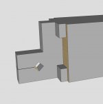
The beams also have the heart center included. You can pay more for "free of heart center" beams which are much nicer, but again not necessary for a shed and beyond my budget.

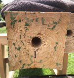
Given that the beams have the center pith they are susceptible to cracking and checking around the perimeter as they dry. In Japan a common way to manage checking is to make a sewari kerf. One cuts a long kerf part of the way toward the pith, then insert wedges to gently force the kerf apart, resetting the wedges as the timber dries. That concentrates the shrinkage at the kerf edges and in the best case prevents checking on the other three surfaces. When the beam is dried, the beam is usually positioned so the kerf in hidden, such as inside a wall or overhead facing up or covered by flooring. If the kerf can't be hidden then sometimes it is filled with a long wedge and planed flush.

You can see the kerfs here just after cutting them in the green beams.
387F13DB-1B7A-4E22-A19A-2C81780FE386_1_105_c.jpeg

And here they are 16 months later when the beams were down to about 15% MC.

A73A3500-471D-485B-8977-B5B68447C7FD_1_105_c.jpeg

I will say that the technique worked pretty well. It did not completely eliminate checking on the other surfaces but did greatly reduce it so that each beam had at least one surface free of checking.

Edit: found one more picture that tells the whole story better:

DE91D025-A668-4666-8B14-73BB0D22B582_1_105_c.jpeg
 
Given the environment in which a shed will live (moist), why did you decide to dry down to 15%?

Interesting approach re checking prevention. I've seen it done in Japan, but only on timbers of much greater dimension: 12" or 15". They used Umeki as well, which was a real pain in construction as they compressed the wedges before filling the relief slots. In some cases they did this to round cross section timber that was going to be used for posts. It was a bit difficult to fathom out what was going on as our translator was not a craftsman and the craftsmen didn't speak English.

Interestingly, (to me anyway) I am sat in my office at the moment looking at my outdoor kitchen. Roughly 15feet by 12feet This is built entirely of English oak and the posts are fully exposed to the weather. These have no cracks or shakes at all - I made it about 4 years ago. Presumably they have not dried that much.
However, a timber framed structure (music room) I made for the house, has significant cracks in some timbers, even though it is from exactly the same batch of wood, felled at the same time. Obviously you are using Lawson's Cypress, which you don't see much in the UK as timber, and when you do it is often used for fencing.
 
AJB Temple":bmbnvcmt said:
Given the environment in which a shed will live (moist), why did you decide to dry down to 15%?

That is an excellent question. Part of the answer is that despite Oregon's reputation as being rainy (it certainly is November through April) the summers here are warm and very dry. It rarely rains June through September. Wood outdoors in summer typically dries to 10-11%. Winter wood MC is about 16-18%. So 15% is about in the middle. Waiting did add about 18 months to the project.

The second answer is that I knew that working by myself it would take several weeks or months to cut all the joinery. Cutting joints when the wood was still fairly wet would risk the wood moving so much upon further drying that the joints would no longer fit. If I had a crew cutting joints and getting the whole thing assembled in month would probably be OK, but that's not what I was facing. I thought it better to wait to cut joinery until the wood had stabilized to equilibrium MC.


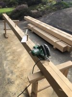
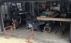
My strategy was to mill the beams down to finished dimensions in stages. This was a challenge given my small (for a project like this) shop space. But I do have a large band saw and jointer that with some extra infeed and outfeed support could handle all but the longest beams.

Here is a beam going over my 12 inch jointer, jointing an adjacent face, and checking for wind and square.49C97B5D-3642-48A0-83E1-4E5D77664B74_1_105_c.jpegA49B2F22-334D-4A1F-96C8-E42BFAB28714_1_105_c.jpegBFC8960A-5051-41BD-9667-FFF67DB828CF_1_105_c.jpeg

I have a planer for thicknessing but it can't handle beams this large. Instead I sent them through the band saw to size over dimension by 5 mm. I tried to take the beams down by removing approximately equal thickness from all the surfaces to reduce unequal stresses.

E6C3333E-D66C-450F-AA3A-C9BFD7D95E34_1_105_c.jpeg

Then the beams sat another 6 months to dry completely over the summer of 2022.
 
This is a very interesting alternative to the traditional European methods of timber framing, which never involve taking big lumps of timber to machinery, and never involve seasoning. The tools are taken to the timber, rather than the other way around, for the very good reason that some of the pieces of oak can weigh over a quarter of a ton. I've been building with green oak* for decades, and I don't think I have ever had a single piece which was square and straight........and even if they had been when I worked on them, they soon wouldn't have been after being in situ for a while. The draw-bore pegged mortice & tenons are what resist the twisting. Frames here inevitably move, and it's just part of the charm. The Japanese approach is more like making furniture.

*It's generally so green that when you pull a spade bit out of the hole it's just drilled it flicks water around. You're sometimes working timber that was standing as a tree a week or two ago.
 
I agree. Like Mike I've handled quite a bit of green oak and have always had no choice really but to take the tools to the job. Oak is so heavy that even working with lever principles, I had to work on the oak as close to the erection point as I could. Most of the time I was on my own. My workshop is quite some way from the main building and is long and narrow. No chance of me running an oak beam over the planer / thicknesser.

Very interesting to see your shop based approach. Probably leads to a finer finish, faster.
 
Yes, this method is much more like furniture making. But it is possible only for these relatively small and light beams. For larger and longer stock then definitely one would take the tool to the work. I had to do that for the longest beams, using a portable electric planer for jointing and squaring up. I was still able to run those through the band saw, but just barely. It was a workout.

For reference, the posts for the shed were just over three meters long and started at 150 x 150 mm square. But each weighed only about 50 pounds/22 kg. When at finished dimensions they were only about 17 kg. The heaviest of the beams was probably about 30 kg green. I'm an old guy but I could still lift them by myself.

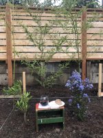
While the beams were drying I worked on the foundation. That started with a jichinsai ceremony, a Shinto ritual meant to appease and pacify the local spirits who might be disturbed by the construction. The ceremony can be more or less elaborate but the minimum requirement is an altar, an offering of rice, salt and sake, a branch of something evergreen, and someone to say a few words hoping for the safety of the construction workers. Since I'm in Oregon I substituted sourdough bread for the rice, and a Willamette Valley pinot noir for the sake. The altar was a painted pine stool my grandfather made for me over 65 years ago. Some bamboo stalks, a native Pacific bay laurel branch, and a branch of a native flowering Ceanothus shrub. And just me in attendance, with my patient wife shaking her head from a distance.

B3E41388-BDB8-4FFB-8EE5-228C9983B485_1_105_c.jpeg

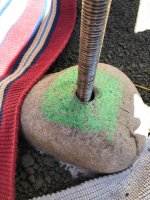
Then the foundation. This consists of six concrete piers buried 600 mm down to frost line, each encasing a threaded stainless steel rod. The rod projects through a hole in a rounded river cobble mortared to the top of the pier.

D99856CA-810B-45B5-AA51-4FCFEE80398B_1_105_c.jpeg

(Then imagine pages falling off the calendar for a year).

The following spring the posts were dry and ready to be scribed to the stones. I drilled holes in the foot of each post to accommodate the threaded rod. Then proceeded to scribe and carve the post foot to precisely match the surface of its stone. This required chalking the surface of the stone, orienting the posts to be in line, square to each other, and precisely vertical. Then setting them on the chalked stone, scribing about the post to match the stone contour, and carving away the parts that shouldn't be there. This took multiple rounds of resetting the posts on the chalk and carving away the high points.

223C3F24-FD5F-431C-B974-B3BB49E9F7D5_1_105_c.jpeg
DB36B571-DCD3-43D6-AF91-50BC829B111E_1_105_c.jpeg

Plumb line to check vertical and a jig attached to some scaffolding to hold the post plumb.

9BA1D24F-1D35-461E-BEE1-2806051C5CC3_1_105_c.jpeg

Scribing using a cobbled together set of washers and a pencil.
550289FC-D47C-4699-BA39-54E289251BB4_1_105_c.jpeg

Carving underway. It is finished when the chalk marks are all nearly even around the edges.

6936B3C4-997B-4459-BF66-8BEB8EFE6468_1_105_c.jpeg
And done.

9E6E22D2-D29B-4EDC-9A31-8C4CB5C926D1_1_105_c.jpeg

3A7CCA52-0FEC-4AC4-B0FF-9B0CDB257C91_1_105_c.jpeg
 
If it’s any consolation Gary all Wives shake their heads at us at some point, and we aren’t doing our job of being a Husband if they don’t, but the spirits were placated obviously, carving the post bottoms like that would have been a nightmare if the spirits had been annoyed.
I did think what on Earth is the point of carving them like that, but the end result is really impressive. It’s the little things! This wood hobby of ours isn’t for people who lack patience as you certainly demonstrate.
Ian
 
The architectural style of posts scribed to stones is called ishibatate. It used to be common in Japan but not so much anymore.

http://somakosha.com/structure-en

The design compared with continuous sills on a perimeter foundation (much more common in Japan) is controversial from what I have read. The link above sites the arguments in favor: raises the structure above the damp earth, allows the building to dance a bit during an earthquake and dissipate the shaking energy, allows cool air flow under the building in hot summers. The arguments against are that it creates a space for vermin to inhabit, allows wind to get under the building to create a chimney effect that accelerates fire, allows the entire structure to get knocked off the piers in typhoon winds or earthquakes.

For my shed, I mainly loved the aesthetic look of a post seeming to rise directly out of the stone. A visual anchor to the ground. And also a bit of "how did he do that?"
 
Thank you Gary that’s very interesting. I have been thinking and I can’t imagine a better way of preserving the bottoms of the posts than the way you’ve done it, both from moisture and insect attack.
 
If anyone is interested in doing an "ishibatate' structure here is a tip for choosing a stone. Pick one that is smooth and slopes in all directions but not too steep. Sloped of course to drain water. Smooth to make scribing and carving easier. Not too steep so you don't need to carve so much from the bottom of the post.

When I went to the local rock supplier for stones I was climbing all over their big pile of cobbles, picking one up and rejecting it, digging another one out and rejecting it, etc. The yard supervisor motored by in his golf cart, watching. He then cupped his hands around his mouth and shouted, "They're just rocks!" We both laughed. I shouted back, "Why did you put the best ones on the bottom?"
 
Fascinating approach.

I think I would possibly have taken the stone to the post for all that neat scribing and carving. 8-)

Interesting to see the new fence change colour as the build progresses. Clearly your wife must have had a temporary shed for a while.....
 
There was some sort of jig involved in setting those steel rods in the concrete, otherwise there would have been no chance that each hole was in the middle of the end of the post. A simple 3x1 template with holes would do the trick.

I've seen that posts-on-stones set up previously, and it does make a very attractive feature. Mr Chickadee uses this technique on his Korean-inspired buildings on Youtube, for instance.

-

I'm afraid there is no way on this planet I could have coped with the long delays built into this build.
 
Everyday is a school day. I’ve never seen anything like that before. You are clearly a very patient man.
 
I'll never need to build anything like this but I am enjoying the really interesting write up. Also the glimpses of the inside of your workshop...
 
Gary,I was particularly interested in the ceremony you describe for erecting the first piece of the work.
It took me back to the late 1970's when I worked on the construction of a power station in the Emirate of Dubai. The contractor was Shimizu from Japan and the site manager performed exactly the same ceremony before erecting the first of the giant steel columns.
 
AJB Temple":18l20gd0 said:
Fascinating approach.

I think I would possibly have taken the stone to the post for all that neat scribing and carving. 8-)

I considered that. In the end, I wasn't sure how well I could reliably position the stone to exactly the same place every time. And then when the shed was assembled, how to get the stones under it correctly positioned in all three axes. But, yes, I could have done it that way.

I'll add that the traditional method does not use a threaded rod. The post just sits scribed onto the stone. That turns out to be surprisingly stable, especially when there are multiple posts. Modern building regulations require the posts to be bolted down. I cut mortices to allow access for a nut but later decided to lower the floor, which meant no room for the mortice. So in my case those threaded rods are just registration pins.

I do live an earthquake zone. But when the big one hits, I'm pretty sure I'll have other concerns than whether my shed is still in the same place.

As to locating those threaded rods accurately, I did make a jig. Squared and leveled with holes to suspend the rods from during the concrete pour. Believe me, I checked and rechecked the locations many times. In the end I got the diagonals within a couple of mm. Patted myself on the back for that one.

D738D522-976F-43A6-8D20-EED147770732_1_105_c.jpeg
 
johnward":3g22yo8d said:
Gary,I was particularly interested in the ceremony you describe for erecting the first piece of the work.
It took me back to the late 1970's when I worked on the construction of a power station in the Emirate of Dubai. The contractor was Shimizu from Japan and the site manager performed exactly the same ceremony before erecting the first of the giant steel columns.

Very nice. A friend who is a construction supervisor for a large Japanese company recommended the ceremony to me. I like that it is a time for everyone involved to think a moment about being safe before the dirt starts flying.

My friend says that hardly anyone today believes there are actual spirits to be pacified but the ceremony is still meant to bring good luck. He said woe be to the contractor who skips the ceremony and then later a worker is injured or something goes wrong with the construction. Everyone will claim it was his fault.
 
Laying out the joinery. I have an online friend advising me who trained in Japan and has been building Japanese style houses in Seattle for over 35 years. He tells me that "layout is everything." Meaning, if you have the layout right but a cut is off a bit you can usually get away with or fix it. But if you make a cut to a layout line in the wrong place you usually have to toss the piece and start over. With a piece of furniture you might be able replace a small part. Not easily or cheaply done with timber frame parts that cost a lot to begin with and take 18 months to dry.

Japanese framing layout is always done from center lines snapped with sumitsubo, an ink line. There are lovely elegant hand carved sumitsubo with silk lines. The carvings often incorporate a turtle and crane. Gorgeous.

I used a modern plastic one from Tajima.
630DA5FE-48AC-43CE-8A64-6A5E5B0DBE6D_1_201_a.jpeg

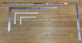
I also used Japanese framing squares, called sashigane. Pronounced roughly sahsh-eh-gah-nay. These things are brilliant. You can buy them scaled in the traditional shaku system, or metric, or Imperial, or both.
839EF9AC-623E-49C7-B1C0-785AECEA8541_1_201_a.jpeg

The two larger sizes shown have a wonderful feature of being made with arms that are 15 mm wide. That turns out to be an extremely useful dimension that is used often for timber framing joinery. I'll show some examples later.

I also am also using Tajima tape measures marked in metric and Imperial. And Western squares that I have had all along for furniture making.

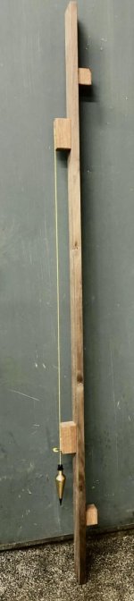
For fun I also made some plumb line sticks and levels. These aren't specifically Japanese. Probably Egyptian?

There is also a water line level in the background.
plum line level - 1.jpeg


25E86D1B-4448-4085-A9E0-93495D0B68D9_1_201_a.jpeg
11364951-D8D1-4ECE-ABA6-CB45DD94DE98_1_105_c.jpeg


For level and plumb, as long as gravity can be relied upon, these will work well.

The plumb line stick is held to the face of a post or other vertical surface. When that surface is plumb the line should just kiss the surface of the stick. There are stand-offs to avoid irregularities in the post or surface that is being measured. Simple and effective. Yes you can also use spirit levels which are more convenient but not necessarily more accurate. Plus, it is fun to make your own tools.
 
I noticed your plumb line the other day and thought what a good design it was with the blocks of wood. Spirit levels can be a bit deceptive at times, particularly on vertical surfaces.
Ian
 
Yes, the plumb line stick is a great design. Of course it works best if you choose a stable wood that doesn't twist or bow seasonally. I used an African "mahogany" for mine since I had some but other would work. And calipers to check the thickness of the offsets.
 
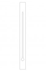
I found an original plumb level in an old wheelwright's shed we were demolishing 25 years ago. It works in a slightly different way from yours. It was a single piece of wood maybe 5 inches wide, 5 feet long, with a 15 or 18mm wide groove cut all the way through it along the mid-line..........tell you what, it will be quicker to draw it:

plum bob level.jpg

The line and the bob were missing, but my partner added his own and used it now and then on that job. It now hangs in his shed. I guess its advantage over yours is that you aren't having to decide if the line is parallel to the stock......you just look at what the bob is pointing at.

The obvious advantage of a spirit level is that you don't have to wait for the line to settle. The Romans used to dampen theirs from swinging by having the bob in a jar of olive oil, but that obviously only works on a free line hanging about a storey height.
 
Fascinating to hear that Japanese framing is done from a centre line.

My instrument registration is all done from a centre line.
 
Malc2098":20ienako said:
Fascinating to hear that Japanese framing is done from a centre line.

My instrument registration is all done from a centre line.

Yes that confused me a little when I first began researching this since they go to all the trouble to dry and square the timbers first. One might think they would use the "mill rule" method. But I guess a lot of their timber framing also uses naturally shaped timbers and the method that works for those works for all.

Once I had the post feet carved I could stand them all in place and mark a level line from which to lay out the post joinery. I used the water level for that.

In the summer of 2022 I re-milled the posts and beams to just over final dimensions, taking care of the thankfully small amount of twisting and bowing that occurred over the previous months and additional drying.

Here is the worst of the lot. You can see the crook that formed at the end of the left post after cutting a straight sewari kerf on the green wood.

7DFB8ED4-07F4-47F5-8CB1-4A6CB8319746_1_105_c.jpeg

And then on to layout for the mortices on the posts.

Having the opportunity to try my hand at the clever and complicated joinery Japanese joinery was my real motivation for this project. Having a functional shed at the end would be a bonus. Please don't tell my wife I said that.

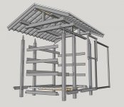
Before I get into the joinery here is an exploded view of the frame for reference and identifying the members.

DA098696-A997-48DC-BE59-3410D2BA1F08_1_105_c.jpeg

The posts you have seen. The floor is supported by perimeter beams that are called ashigatame (ah-she-gah-ta-may). Intermediate support for the floors is done by sleepers called oobiki (oh-oh-bee-kee) that are joined to the ashigatame. Floor joists will sit on the oobiki and ashigatame.

The thinner horizontal boards joining the posts above the floor are called nuki (new-key). They function more or less like girts in western timber framing.

Roof framing varies a lot. The system I chose is one called orioki. It is a old method used mostly for rural structures like barns that have a regular set of bays. It is very strong but not allow much flexibilty in floor plan. In this system there are tie beams that connect the posts across the structure's short dimension. Eave beams then sit on top of the time beams. A more common method is to set the eave beams on the post first and then set the tie beams on top of those. That system is more flexible since the tie beams are not limited to the post positions. That allows rooms of different dimensions below. And it creates a higher ceiling so it is more often used for residential construction.

You will probably notice that there are no diagonal/triangular knee braces at the corners. That is a peculiarity of traditional Japanese construction. On the one hand, diagonal bracing is clearly a good way to stiffen a building. With over a thousand years of experience and a sophisticated understanding of building wood structures, why did they not use diagonal bracing? I certainly do not know. One idea is that diagonals conflict with the Japanese esthetic, which values strong horizontals and verticals.

Diagonals just look funny and ugly and wrong and folks don't want to see them. Supporting this idea is that in post WWII construction and with engineering for better earthquake resistance, modern buildings in Japan do use diagonal bracing. But it is hidden in walls and attic spaces and floors.

I find this cultural difference in how people interpret a building's structure fascinating.

Next up I'll show the joinery I used for the floor beam/posts and nuki.
 
I spent a lot of time thinking about the joinery between the perimeter floor beams and posts. My research revealed six or more ways to do it with advantages and disadvantages for each. Some resisted tension better but expose tenons to the elements. Others were more weather resistant but less able to withstand tension. Some gave more support for the floor and loads, but removed more wood from the post and weakened it.

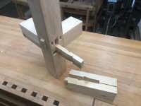
If the stakes were higher this would have been a situation that required a master carpenter with decades of experience. Instead it was just little old me fooling around and building a garden shed. I did my best and came up with this scheme for the corners. (I have another for the middle posts.)29301912-A4F5-45BB-B56D-11F7028D406A_1_105_c.jpeg

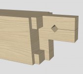
This is not a traditional mortice and tenon. It actually is a new version that I have read is stronger than used traditionally.

The tenon is short and not through nor wedged or pegged outside the post. That limits the relish which usually reduces its resistance to tension. But,the short blind tenon is split and fixed by a diamond shaped peg. The peg spreads the tenon to make it act like a dovetail. Under tension the tenon spreads and wedges tighter into its mortice which does resist tension.

Here are more diagrams and pix. I can't seem to find a finished example with the mortice for the peg but you can probably get the idea. I'll say more later about the little stub tenons that are part of the joint.

FA7E0A83-AACD-404D-B5DA-0CB2AE45FE2F_1_105_c.jpegBC65DC19-C451-445D-8064-A64450C327F4_1_105_c.jpeg
 
I've always though the Japanese over-complicate things in their joinery! :) Here's the traditional European joint of a beam/ plate into a post:

5T7dPFl.png

3KQhQUP.png

It's this joint here:

b3HqI98.png

Granted, European framing almost never has the situation where two plates on the same level meet at a corner post, but if they did, it would be the same joint, but with the tenons staggered (one up, one down).
 
Great sequence of posts. Very interesting.

It's true in a way that the Japanese culture overcomplicates things..... to a western eye. But the complexity is an intentional part of both the aesthetic and the craft. You see it in everything, including what appear to be simple things like slicing sashimi, or indeed origami.

Regarding the structure, it is hard for western framers to fathom the complex joints and apparent absence of bracing in temples and domestic building traditional joinery. Having read about it as far as possible in western texts, and asked skilled carpenters in Japan (via interpreter only, so something is lost), they usually refer to earthquake resistance and the building not being too stiff in any direction to withstand (NOT resist) earthquakes which create both lateral movements and heave. The intent being to keep the centre of gravity more or less vertical during a seismic event, individual floors must slide against each other, hence the tray type beam constructions that are only partially anchored. And hence the large overhangs too. This web site shows it quite well: https://www.morganmarzo.com/writing/201 ... resistance.

Some texts also suggest that the methodology fairly readily allows repairs and partial replacements, without too much disturbance to other parts of the structure. I've never seen this demonstrated though.

It seems to me that the Japanese must have an entirely different approach to structural calculations. A western structural engineer would be bemused. The approach to foundations is also quite different in old buildings, though perhaps would be familiar to our medieval architects who did not find a need to plonk in four foot deep concrete trenches to hold up a single story oak outbuilding......(building control are you listening?)
 
Mike G":1j3gvavk said:
I've always though the Japanese over-complicate things in their joinery! :) Here's the traditional European joint of a beam/ plate into a post:

Granted, European framing almost never has the situation where two plates on the same level meet at a corner post, but if they did, it would be the same joint, but with the tenons staggered (one up, one down).
Yes, that joint exists in Japanese construction as well.
22730868-19CF-4EBC-AB15-F78F8F37B9E4_1_201_a.jpeg
This version is not pegged because there is not enough relish on the tenon for it to be secure. This joint would probably be used as an intermediate member with the ones above and below providing resistance to tension. It could be pegged if the posts were larger or the tenon made through.

I suppose one man's "over-complicated" is another mans "elegant refinement." :D The example you showed is of course perfectly fine for most work and most conditions. But it can be improved. For one, resistance to twist is provided only by the narrow tenon. In the example I showed, twist is also resisted by those stub tenons placed farther toward the surfaces of the beam. The stubs on the bottom edge also help carry the load on the beam. Aesthetically, the angled feature in the simpler joint exposes the joinery. That can be appealing. But in both western and Japanese furniture and building, exposed joinery is generally viewed as less refined than hidden joinery. Kind of like showing exposed screw heads is OK structurally and fine for rougher work but not on fine work.

And I agree that designing to have two beams meet a post at the same level introduces another complication. The over/under solution is common and what I used, too. That reduces the height of the tenons by half, which also means less resistance to twist if the tenon alone is doing that work. Hence the multiple stub tenons.

And if you thought that joint was over-complicated, wait until you see next one, which has three beams meeting a post at the same level. Let me go find the pictures. I'll be right back.
 
OK, I found some pictures of my joinery model for the three-way joint. I did this at about 2/3 scale just to make sure I understood the 3D layout and cut sequence.

6121B694-8991-485D-9FD2-97192B0DAA36_1_105_c.jpeg

Here are how the beams assemble, minus the post, to show how they interlock.

258F39F6-02F6-44DB-AD70-0A7387E89569_1_105_c.jpeg

And the assembly sequence. The beam with the short through tenon goes in first, then the one with the long tenon.

83C8A7E0-CBB1-4E32-AD44-A4FA6327C98E_1_105_c.jpeg
1729D4BB-A290-4C2F-8118-EFBE915D9B28_1_105_c.jpeg

When assembled the entire joint is locked down by those thin tapered wedges called shachi sen. More about those and how they are used later.

FDA8BCD5-3009-48C0-8C1A-98BAE29C7C20_1_105_c.jpeg

If the joint is oriented so that the shachi sen face away from the viewer the entire assembly has a nice, clean look.

3E7B54BD-C591-40FC-9725-0F48571B08BC_1_105_c.jpeg
 
Back
Top