• Hi all and welcome to TheWoodHaven2 brought into the 21st Century, kicking and screaming! We all have Alasdair to thank for the vast bulk of the heavy lifting to get us here, no more so than me because he's taken away a huge burden of responsibility from my shoulders and brought us to this new shiny home, with all your previous content (hopefully) still intact! Please peruse and feed back. There is still plenty to do, like changing the colour scheme, adding the banner graphic, tweaking the odd setting here and there so I have added a new thread in the 'Technical Issues, Bugs and Feature Requests' forum for you to add any issues you find, any missing settings or just anything you'd like to see added/removed from the feature set that Xenforo offers. We will get to everything over the coming weeks so please be patient, but add anything at all to the thread I mention above and we promise to get to them over the next few days/weeks/months. In the meantime, please enjoy!

Bar Clamps

Dr.Al

Old Oak
Joined
Dec 31, 2020
Messages
4,033
Reaction score
2,988
Location
Dursley, Gloucestershire
Name
Al
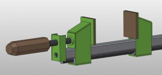
barclamps_model_800.jpg


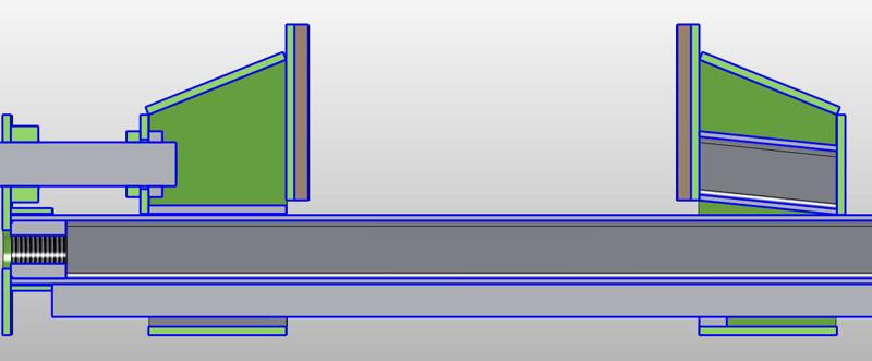
I'm planning to make some bar clamps based on the design by Neil Paskin (link below). I'm sure it would be more sensible to buy some, but I like the idea of having some robust clamps that all sit at the same level and rest comfortably on the bench. Buying a lot of long, fairly heavy-duty clamps would probably be expensive and unless I went with the T-bar type, they wouldn't have the flat surface on which to support workpieces. Even the relatively cheap options like sash clamps are likely to be £30 or more for a metre length clamp; by my calculations the set of clamps I'm going for should cost me about £12 each (ignoring time and argon). Also (and probably more importantly) it'll be a fun project as I enjoy TIG welding and haven't had many projects involving much of it recently.

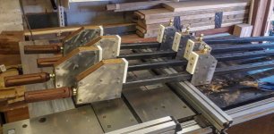
Neil Paskin didn't provide any real details of the design, so I decided to start with a CAD model (image of the latest version above) and a quick prototype made much shorter than the final clamps will be:

barclamp_prototype_800.jpg


While making the prototype, I found various issues with my original design (mostly designing to engineering tolerances rather than allowing for welding movement!), so I updated the CAD model to suit and the final clamps should look more like the image at the top.

This really won't involve much woodworking (apart from making the handles and the jaws): it's almost entirely a welding project. However, I'm writing a build log on my website and on the MIG welding forum; is this something that would be of interest to anyone on here? If so, I'll keep posting updates to this thread as well.

This is the video on which I'm basing the design:

[youtubessl]P0wLjQqf-zM[/youtubessl]
 
Not just interested in the write up, I'm interested in the clamps. Careful what you say because you could find yourself going into production!! :lol:
 
I feel there might be a weak point in the flat strip used for the fixed end of the clamp. Perhaps a short length of box section might be better.
In an ideal world, clamps don't need to exert huge forces but just now and then some excessive persuasion can be needed.
I don't know how many members here have hot metal glue guns I would think there should be a good degree of interest.
I quite like Neil Paskin's work and often watch his videos.

Bob
 
His work is fun, but I hate his voiced-over videos.
 
9fingers":dcmcvddx said:
I feel there might be a weak point in the flat strip used for the fixed end of the clamp. Perhaps a short length of box section might be better.

I agree and have already got a plan to deal with that if need be (I'm going to do some strength testing on the prototype soon). The plan looks something like this:

1620142156722.png

(welded to the green box section at the bottom obviously).

I might instead do it with a longer bar that goes all the way down past the box section; depends what I feel like when I get there!
 
As there seems to be some interest, I'll continue...

barclamps_model_800.jpg


The model above is fairly close to how Neil Paskin designed his bar clamps (as far as I can tell from the limited information in the video). My plan is to make eight clamps; four will have a maximum clamping length of 1 metre; the other four will clamp up to about 1.7 metres. These lengths were chosen based mostly on material availability: I'll be using four 3 metre lengths of threaded rod. Allowing for the 1 metre clamping length of the shorter bars and adding the extra length required due to the shape of the jaws, the 1 metre clamps will use 1140 mm long pieces of threaded rod. The "offcut" will be about 1860 mm and hence that will be the basis of the size of the longer bar clamps.

barclamps_model_screw_jaw_closeup_800.jpg


This shows a close-up of what I'm calling the "screw jaw". This shows one of the more significant changes I've made relative to Neil Paskin's design. In the original, the end plate was welded onto the end of the box section piece that forms the main bar. For mine, I decided to attach this in a removable way using an M12 hex-head screw. A piece of steel is welded into the end of the box section and has an M12 hole drilled and tapped in the end. There's a short length of 30 mm × 30 mm × 2 mm box section welded to the end plate - this stops the end plate from rotating and the M12 hex-head screw (not shown in the model) holds it tight to the main 25 mm × 25 mm × 2 mm box section.

The advantage of this modification is that both jaws will be removable from their box section bar, which will mean that I can make longer or shorter bar clamps in future simply by welding some threaded bar to some box section.

barclamps_cross_section_800.jpg


This image shows a cross-section through the bar clamp. Another change I've made to Neil Paskin's design is to make the sliding jaw (right-hand side) the same width as the screw jaw. This means I can use the same size bar stock to make the parts.

Apart from dimensional details (as I don't have any dimensions for Neil Paskin's version) and build process (due to available tools), that's pretty much all I'm changing.
 
The first thing I did in the build was some investigation into welding the threaded bar to the box section. This is an important part of the design and it's important that the welds are relatively tidy so that the screw jaw can slide freely and the half-nut in the sliding jaw doesn't interfere with the weld beads.

In the original video, Neil Paskin used his gasless MIG welder to attach the threaded rod to the box section. I don't have a MIG welder, so I needed to explore other options. The threaded rod I have came with zinc plating; to TIG weld this I would need to remove that plating, but that would expose the threaded rod to the possibility of rust and it can't be painted as the thread would no longer be usable.

barclamps_arc_welding_attempt_800.jpg


My first attempt to overcome this was to get the arc welder out. My arc welding skills are... well... limited, as you can see in this photo (which was my fourth attempt). I could have carried on practising and I'm sure I would have got there. However, I noticed that the zinc plating near the weld beads had turned a matt grey. I suspected that this was a sign that the zinc plating had gone, so I sprayed the sample with some water to see what happened.

rusty_zinc_plating_800.jpg


As I suspected, the plating is no longer doing its job, so this doesn't seem like a good option (even if I could master the art of arc welding).

threaded_rod_tig_test_800.jpg


Given that the zinc wasn't surviving the arc welding and that TIG welding is a much more pleasant process (fume & splatter free and also a lot more controlled), I went back to TIG - the test piece is shown above. It will still be susceptible to corrosion, so I will have to apply some ACF50 or Metalguard or similar. My workshop has a dehumidifier running all the time (controlled by a humidistat) and there is lots of unprotected steel. So far I haven't had a problem with rust, so I'm hoping that these new bar clamps will survive. Apart from the box section and threaded rod, most parts of the clamps will be painted or can easily be oiled without risking getting oil onto the wood being clamped, so it shouldn't be too bad and I can always replace or de-rust the box section bars if they do corrode (as these pieces are quick and easy to make). I could have used stainless steel for the box section and the threaded rod, but this would have been a heck of a lot more expensive.
 
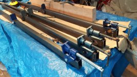
I totally loved making my 5' clamps. Super massively over-engineered (I was asked 'What part of the bridge are they designed to replace?' haha), but if you're going to make something, make it to last!
 

Attachments

  • 07-finished-2.jpg
    07-finished-2.jpg
    136.1 KB · Views: 7,883
Having decided that everything is going to be TIG welded, the next job was to clean all the zinc off the threaded rod and nuts and to clean the mill scale off the box section and flat bar. Getting rid of the zinc plating is really easy as it's a thin layer that can easily be removed with citric acid, which is cheap and easy to buy in powder form (and I bought a big tub of it a few years ago). For the mill-scale, I could remove it with an angle grinder, but that's a really unpleasant process and the citric acid is a reasonably effective alternative.

gutter_as_citric_tank_800.jpg


As most of the parts I'm working with are long and relatively narrow, I used a couple of lengths of "square line" gutter as a citric acid bath. There's an end cap on each end of the guttering; I put some grease on the seals to help ensure the acid mixture stayed in the gutter, but I don't know whether that was necessary. I'd worried that these end caps are designed to stop small amounts of water (which is typically flowing away from the end cap) leaking through and I wasn't sure how it would cope with a filled-up gutter.

box_before_and_after_citric_800.jpg

thread_before_and_after_citric_800.jpg


These photos show the box section and threaded rod before and after being in the citric acid "tank". I used about a mug full of citric acid powder in each bit of gutter and filled it up with cold water. It's much quicker with hot water, but I had a lot of pieces to go through and figured it would be cold for most of the time so it wasn't worth the effort of heating the water. The zinc comes off in a matter of minutes, but I tend to leave each set of pieces in the gutter overnight to be safe.

When the parts come out, they need a bit of immediate attention. The threaded rod just needs to be thoroughly dried (I use my air compressor to blow-dry them) as they will rust if left dripping. The box section needs to be wiped clean of any remaining oil and then needs a quick rub with a Scotchbrite pad. I used a maroon (360 grit) pad (and actually a "Hermes Webrax Hand Pad" rather than genuine Scotchbrite). I also use the air compressor to blow out excessive water from the inside of the box section.

The mill-scale on the flat bar (I'm using 3 mm × 30 mm and 3 mm × 50 mm bar) is a lot thicker than that on the box section. The citric acid doesn't completely shift it (at least in the time I've been allowing it), so I use a "non-woven preparation wheel" on the angle grinder to clean the last bits of scale off. I've tried using this wheel on a bit of the flat bar that hadn't been in the citric bath and it took much, much longer to get the steel clean, so it's definitely worthwhile putting it in the citric acid before trying to clean it. With hindsight it probably would have been easier to buy some 3 mm cold rolled sheet, but this would have been a lot more expensive.
 
Peri":1j7cafhw said:
I totally loved making my 5' clamps. Super massively over-engineered (I was asked 'What part of the bridge are they designed to replace?' haha), but if you're going to make something, make it to last!

Ooh, they're really pretty!

I don't suppose you did a build thread at the time did you? I'd love to read it!
 
Hiya Al, looks like an interesting project.
I use 4mm box section with cramp heads (paramo and record ones are far better finished than the new ones by Rutlands etc) although I believe they were originally designed to be used with wooden bars. (I think?)
xaGTaAT.jpg
The only reason I post this is that Custard kindly pointed out in a different thread on a different site that one minor 'failing' of these type of heads is that the face or mating angle of the head can be pushed back a little when cinching the cramps tight. There is some play between the bar and the head. Hence the heads would damage edges on occasion especially on thinner stock.
Being Custard he also suggested a neat solution of using shims or small wedges to keep the heads square to the bar which works well on this type of head

Just wondering if this might possibly help you out at this early stage although I'm not sure it affects your design. Just a heads up in case it might.

Looking forward to progress. Interesting thread. ;)
 
Chris101":2y9r1wp4 said:
Hiya Al, looks like an interesting project.
I use 4mm box section with cramp heads (paramo and record ones are far better finished than the new ones by Rutlands etc) although I believe they were originally designed to be used with wooden bars. (I think?)

The only reason I post this is that Custard kindly pointed out in a different thread on a different site that one minor 'failing' of these type of heads is that the face or mating angle of the head can be pushed back a little when cinching the cramps tight. There is some play between the bar and the head. Hence the heads would damage edges on occasion especially on thinner stock.
Being Custard he also suggested a neat solution of using shims or small wedges to keep the heads square to the bar which works well on this type of head

Just wondering if this might possibly help you out at this early stage although I'm not sure it affects your design. Just a heads up in case it might.

Looking forward to progress. Interesting thread. ;)

Thanks for that. I'm going to put "soft" jaws on my vice (much like Neil Paskin did). I'm sure there will be some pivoting of the jaws when they tighten. It had occurred to me that it might be better to have these slightly tapered top-to-bottom for this exact reason, but I'll do some experimentation when I'm closer to that point. At the very least I might put a radius on the bottom edge (and maybe the other edges too) so that if they tilt up there won't be a sharp corner biting in.
 
Interesting thread.

Does it make economic sense to make them taking into account the labour time? I know some people like making tools and do a fine job, but I struggle to find enough energy to make inroads into the to do list of stuff at home.
 
Possibly a hi jack.

I have plenty of various clamps as I guess most of us do, what I would like to see is some clever way of increasing their jaw depth whilst retaining the rigidity of the clamping area.
I know that is one reason that the bessimer type clamps are so popular.

So two points
OP, have you considered making the clamp face longer (taller).
And to anyone else, ideas for adapting conventional clamps.
 
AJB Temple":2082tzxm said:
Does it make economic sense to make them taking into account the labour time?

Almost certainly not. I think they will cost me about £12 each for 8 clamps, so just under £100 in parts. Ignoring the prototyping time, I'm expecting it to take me a couple of weeks of evenings & bits of weekends to make them. If we (probably rather generously) compare them to some T-Bar clamps, the cost for 4 long and 4 short clamps would be £378. Even ignoring the fact I wouldn't buy as many if I were paying "full whack" for them, a sensible hourly rate would definitely make up more than £278.

However, I like the design (they look a lot nicer to use than T-Bar clamps from the videos I've seen where Neil Paskin uses them) and most importantly, I think I'll really enjoy making them.

AJB Temple":2082tzxm said:
I know some people like making tools and do a fine job, but I struggle to find enough energy to make inroads into the to do list of stuff at home.

I'm not claiming for a second that I do a good job of making inroads into the to-do list of stuff at home :D, but I do enjoy making tools; often more than I enjoy making "end products" to be honest (possibly partly because I'm not very good at the "making things pretty" bit).
I find (TIG) welding quite a relaxing thing to do and if I've had any frustrations at work in a day, it's a great way to take my mind off things (as are hand planing wood, turning steel and a few other things). In that sense, what I'm making is largely irrelevant.
 
Lurker":lqbysqs8 said:
I have plenty of various clamps as I guess most of us do, what I would like to see is some clever way of increasing their jaw depth whilst retaining the rigidity of the clamping area.
I know that is one reason that the bessimer type clamps are so popular.

What are "bessimer type" clamps? I googled the term but nothing helpful came up.

Lurker":lqbysqs8 said:
OP, have you considered making the clamp face longer (taller).

That's a very interesting thought.

I'm still umm-ing and ah-ing about the clamp face to be honest. If you look at the first post in this thread, you'll see that there's quite a difference between the prototype and the current model - the prototype had much taller jaws than the current model. They looked a bit out-of-proportion on the prototype to me, but the prototype does have the advantage of tall jaws. I'm not really sure what applications would need them where I'd also want very long clamps.

As I increase the height of the jaws, the point that @Chris101 raised comes more into play - if the jaws tilt when tightening, then the top of the jaws really isn't doing very much. That can possibly be dealt with (assuming its consistent) either with tapered wooden jaw faces or by very careful angled welding of the steel jaws.

Perhaps another option for these is to add some extra tall auxiliary jaws that slot onto the standard ones... hmmm... food for thought.

The main application where I find I need deep clamp jaws is for clamping stuff a long way away from the edge. In those applications I tend to reach for my big Lidl F-Clamps that look like this. In that situation I don't need (and probably don't want) clamping all across the jaw, just clamping a long way away from the bar. I'm guessing that's different to what you're referring to when you talk about bessimer clamps.
 
Pictures showing what the model looks like with short and tall jaws:

short_jaws.jpg

tall_jaws.jpg

(Note there are some other changes to this model as I've been playing around with the end plate support - I'm still undecided as to whether the bar sits on the jaw bases or on one jaw base and an extended end plate)
 
Sorry! Just me being dumb
I meant Bessey clamps as I knew they were popular with the pros and rich folks ;)
I suppose I meant parallel clamps

I have those deep Lidl f clamps and jolly useful they are too.
But just occasionally I would like a bit more clamp face without racking on my longer sash clamps.
 
Lurker":29hsi469 said:
Sorry! Just me being dumb
I meant Bessey clamps as I knew they were popular with the pros and rich folks ;)
I suppose I meant parallel clamps

Ah yes, I've got a couple of (much cheaper than Bessey) parallel jaw clamps and I like them a lot and would very much like more of them. I've got these ones - I only bought two as they had two left in a sale and I was being a cheapskate! They work well, but I'd be interested to know how much better the more expensive ones like these ones are. At twice the price, I'd like to think there's something different about them but it's hard to tell without using them in anger I guess.
 
Dr.Al":2uw0nxqd said:
Pictures showing what the model looks like with short and tall jaws:

file.php


file.php


(Note there are some other changes to this model as I've been playing around with the end plate support - I'm still undecided as to whether the bar sits on the jaw bases or on one jaw base and an extended end plate)

and because parametric CAD is fun...

silly_tall_jaws.jpg

:lol: :lol: :lol: :lol:
 
droogs":1r68l7p8 said:
Allways thought he sounded a bit Sandwell and Dudley

I'm not sure exactly where he's from - I just remember a comment on one of his patreon threads saying his accent sounded like a cross between West Midlands and North-East Australia and the response from Neil Paskin was "spot on" or words to that effect.
 
barclamps_model_jaw_mover_800.jpg


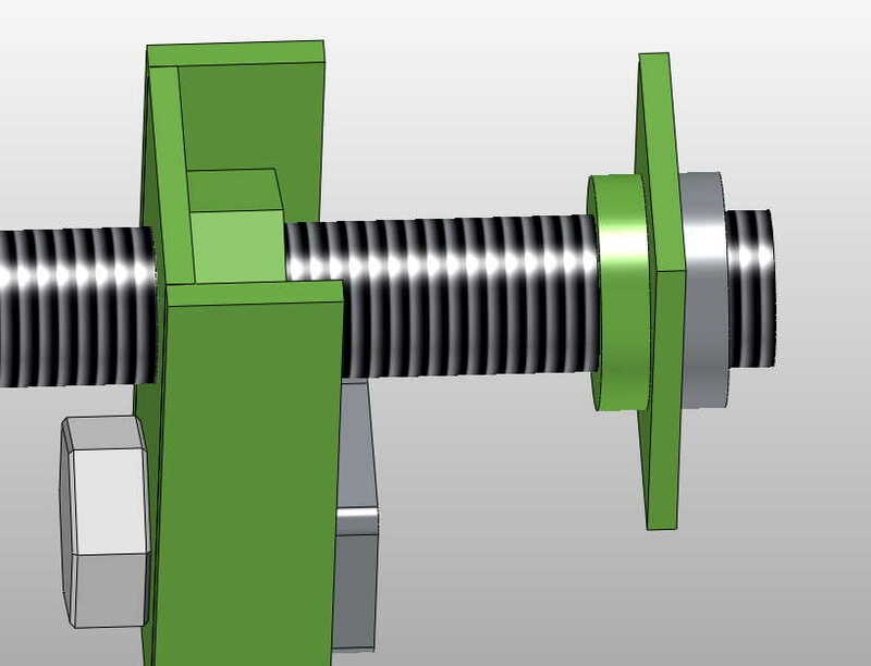
The screw jaw is moved by a 150 mm long piece of M16 threaded rod. The plate on the back of the jaw (shown in isolation on the right-hand side of the image above) is held on the threaded rod by two clamping pieces. These are attached to the threaded rod but neither they nor the threaded rod is attached to the plate, so the threaded rod can rotate freely relative to the plate. Although it's not shown in the model, the hole through the plate is oversize (18 mm) and there's a reasonable amount of clearance between the clamping pieces and the plate so that the threaded rod doesn't have to be perfectly perpendicular to the plate or perfectly aligned with the centre of the hole.

In the original video, Neil Paskin made these clamping pieces by holding an M16 nut on a piece of threaded bar in the drill chuck and "turning" them with an angle grinder (and then cutting in half with a hacksaw). That's a perfectly reasonable approach, but I've got a lathe.

barclamps_screw_jaw_clamp_piece_in_lathe_800.jpg


This photo shows the set-up I used for turning the nuts to size: it's just a scrap bit of M16 threaded rod held tightly in the chuck with a washer to hold the nut away from the jaws. This isn't a good way of holding threaded rod as the jaws will damage the thread; I probably should have fitted my collet chuck and used that (as it would have given better concentricity of the gripped thread), but for this application I decided it probably didn't matter and this way was easier.

barclamps_screw_jaw_clamp_pieces_part_done_800.jpg


This photo shows a sort-of before-and-after of the lathe work - some of the original nuts and some that have been turned.

barclamps_screw_jaw_clamp_piece_hacksawing_800.jpg


I probably could have used a parting tool to cut the nuts in half, but I decided to just do it with a hacksaw.

barclamps_m16_thread_in_bandsaw_800.jpg


While I was at it, I used the bandsaw to cut up the M16 threaded bar into 150 mm lengths; my home-made bandsaw cut-off table with its stop made this a very quick process.

barclamps_screw_jaw_clamp_pieces_finished_800.jpg


The finished clamp pieces are shown in this photo (along with the M16 threaded bar bits). The smooth (outer) side of each half-nut will be against the plate in the screw jaw. The rough hacksawed side will be facing out but the rough finish will disappear once I melt it with the TIG torch.
 
Last night I was idly wondering if it was worth having a thrust bearing on the moving jaw.
ebay was about £2.50 a pop but i did not get round to searching Banggood for a pack of 10 direct from China
Chinese bearings can be incredibly cheap for non critical applications.
You don't need quality or precision but might give a nice feel to your clamps.

Bob
 
9fingers":1k4ycslf said:
Last night I was idly wondering if it was worth having a thrust bearing on the moving jaw.
ebay was about £2.50 a pop but i did not get round to searching Banggood for a pack of 10 direct from China
Chinese bearings can be incredibly cheap for non critical applications.
You don't need quality or precision but might give a nice feel to your clamps.

Bob
I reckon youd get as nice a feel from a pair of conical washers.
 
9fingers":3fkm91df said:
Last night I was idly wondering if it was worth having a thrust bearing on the moving jaw.
ebay was about £2.50 a pop but i did not get round to searching Banggood for a pack of 10 direct from China
Chinese bearings can be incredibly cheap for non critical applications.
You don't need quality or precision but might give a nice feel to your clamps.

Bob

That's a good thought (assuming the heat from welding the clamp plate doesn't bugger the bearing). I'll have a look around & see if I can find any cheap options.

Thanks!
 
I've ordered some budget 51103 thrust bearings - £15 for ten (with a UK supplier, I could have got them for about £8 for ten from China but I went with the impatient option). They're 17 mm ID, 30 mm OD and 9 mm long so should fit quite neatly around the 16 mm threaded rod and against the 30 mm wide plate. I'll probably try one on the prototype to see what it's like & how easy it is to get the spacing tight enough for the bearing not to come apart but loose enough to allow for welding movement.

It's also going to make masking up for painting a complete pig, but I'll jump off that proverbial bridge when I get to it.

I suspect it'll be absolutely fine without the bearings (the movement is never going to be silky smooth with the welding tolerances associated with the sliding motion along the rail), but it might make the final tighten a bit smoother.

The bearings are rated for a static load of 21.2 kN and a maximum speed of 12,000 rpm, so that should be okay anyway :D
 
Just as an aside, what thread do you think is optimal. I only ask because all my clamps are second hand. Some of them have a very fast thread that quickly closes the gap, others need a lot of turns. Prefer the former myself. Must be a deliberate design feature.
 
Different tools for different jobs there - the finer threads will give (potentially) a lot more clamping force than the fast ones, at the expense of more time needed to set up.
 
AJB Temple":3kz00bkd said:
Just as an aside, what thread do you think is optimal. I only ask because all my clamps are second hand. Some of them have a very fast thread that quickly closes the gap, others need a lot of turns. Prefer the former myself. Must be a deliberate design feature.

I guess it depends on what you want out of it. A fine thread will give more mechanical advantage so in principle will give more force for a given torque. Having said that, the peaks and troughs will be shallower so the thread will be weaker. A coarse thread will move quicker and, for woodworking applications, will probably be fine.

One of the things I like about the bar clamp designs I'm making is it's (kind of) the best of both worlds. It uses a 2 mm pitch thread for clamping, which is relatively fine so gives plenty of force for a given amount of effort, but the sliding jaw can be moved in increments of 1.75 mm, so you never need to move the screw jaw very far. Obviously it would be better with a trapezoidal thread, but that would be a lot more expensive!
 
Thanks. Makes sense. Struggling to think of a woodworking application where a great deal of clamping force is needed - presumably one can over do it and squeeze too much glue out. My old Record clamps can easily exert more force than I have ever needed, even with edge to edge gluing of boards.

It would be helpful at times if clamps were designed so that they can be linked together to make double the length.
 
AJB Temple":2vfmv3gu said:
Thanks. Makes sense. Struggling to think of a woodworking application where a great deal of clamping force is needed - presumably one can over do it and squeeze too much glue out. My old Record clamps can easily exert more force than I have ever needed, even with edge to edge gluing of boards.

It would be helpful at times if clamps were designed so that they can be linked together to make double the length.

many are designed with couplers in mind.
This is a bessey coupler
88DE50F5-779B-4109-BD17-4F69529DBE1C.jpeg
Bob
 
AJB Temple":2y2gvinq said:
Thanks. Makes sense. Struggling to think of a woodworking application where a great deal of clamping force is needed - presumably one can over do it and squeeze too much glue out. My old Record clamps can easily exert more force than I have ever needed, even with edge to edge gluing of boards.

It would be helpful at times if clamps were designed so that they can be linked together to make double the length.

The threaded ends of my bars should make it possible - I've had a few ideas about how to make some robust couplers (for all those times when I need to clamp lengths longer than 1.75 metres :lol: :lol: :lol: ).
 
I've never seen those. I do have a dozen or so Bessey clamps in smaller and specialist sizes, but never come across those. Thank you.
 
As I've decided to attach the ends to the bars with M12 screws instead of welding them on as Neil Paskin did, I have to include an M12 tapped hole in each end of the bars. There are a few ways I could have done this:

  • File two corners off an M12 nut, somehow hold it central in the end of the bar and weld into place.
  • Weld some steel into the end of the bar, then drill into the end (probably in the lathe) and tap M12.
  • Make some 20 mm square inserts with a central hole tapped M12.

The first option has the advantage that it doesn't need any special tools. The second option has the advantage that it makes sure that the tapped hole is central with respect to the box section. The third option is (I think) the quickest, so that's what I'm going with! I've got a 250 mm length of some finest grade skipium that happens to be the right size. I decided that the easiest approach was to cut this into 60 mm lengths then drill and tap each length using the lathe. The pieces could then be cut up into 10 mm lengths. I don't care too much about the finish on the face as I'm going to be welding over it anyway.

barclamps_bar_insert_in_four_jaw_chuck_800.jpg


This photo shows one of the 60 mm lengths after I've drilled it 10.5 mm and tapped it (with a spiral flute tap) M12 under power. After getting the first bar into the chuck and centred properly, I marked two of the jaws with a marker pen so I could just undo those two jaws, swap the bars over and tighten the same two jaws. This won't result in absolute precision of the hole in the centre of the bars, but it really doesn't need to be precise for this application.

barclamps_bar_inserts_partially_cut_800.jpg


This photo shows three of the bars after they've been removed from the lathe chuck and one after it has been cut up into slices. The little vice on the left-hand side of the photo hasn't been used for a long time: I used to use it for holding stuff down on my mini-lathe when trying to do milling operations. Since getting my little milling machine, it hasn't been out much.

barclamps_holding_short_inserts_in_bandsaw_800.jpg


For this operation the little vice was really useful for holding the short lengths of bar in the bandsaw vice so that they could be chopped up into little square nuts.

barclamps_bar_inserts_800.jpg


This photo shows all of the resulting inserts. I need two per bar, so this is way more than I need for the eight clamps I'm planning to make, but I figured I might as well cut the whole bit of steel up and then I can keep the spares in case I want any other lengths in the future.
 
Back
Top