• Hi all and welcome to TheWoodHaven2 brought into the 21st Century, kicking and screaming! We all have Alasdair to thank for the vast bulk of the heavy lifting to get us here, no more so than me because he's taken away a huge burden of responsibility from my shoulders and brought us to this new shiny home, with all your previous content (hopefully) still intact! Please peruse and feed back. There is still plenty to do, like changing the colour scheme, adding the banner graphic, tweaking the odd setting here and there so I have added a new thread in the 'Technical Issues, Bugs and Feature Requests' forum for you to add any issues you find, any missing settings or just anything you'd like to see added/removed from the feature set that Xenforo offers. We will get to everything over the coming weeks so please be patient, but add anything at all to the thread I mention above and we promise to get to them over the next few days/weeks/months. In the meantime, please enjoy!

Bar Clamps

The next job was to cut all the flat bar pieces to length (about 400 pieces in total as a result of making so many clamps in one go!). To help me keep track of things, I made a cutting list describing the size of each component (grouped by size of the bar from which they will be cut) along with the number of pieces required per clamp. If anyone feels inclined to make any of these clamps, let me know and I'm happy to send a copy of the cutting list with all the dimensions.
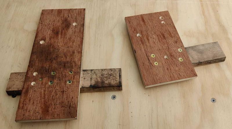
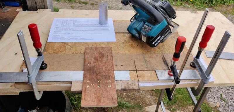
sawing_jigs_800.jpg


barclamps_flat_bar_cutting_jig_800.jpg


Most of these cuts were done with the jig shown in the second photo above. This was made out of an old bit of OSB (oriented strand board), a bit of hardboard (which, at 3.2 mm thick is very slightly thicker than the 3 mm flat bar) and a couple of fence jigs (shown in the first photo) that I'd previously made for cutting steel square with my metal-cutting circular saw (which is a lot nicer to use than an angle grinder, although an angle grinder would work fine - Neil Paskin used an angle grinder in his video). The right-hand end (in the photo) of the hardwood guide bar on both of these jigs was cut with the circular saw, so that end can be quickly lined up with a marked cut line; the saw runs along the plywood edge to make sure it cuts at 90°. However, for this jig that reference edge on the hardwood guide bar isn't used (although the guide bar itself helps keep the metal bar in place). I fixed the jig to the bottom plate with a couple of screws and used the saw to make a cut into the OSB and hardwood. I then measured from the far side of the kerf when placing stops for repeatable cuts.
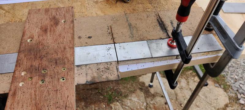
barclamps_flat_bar_cutting_jig_with_bar_800.jpg


In use, a piece of steel is slid underneath the saw alignment jig up to one of the lines and then the saw is used (against the fence) to cut the part to length. None of the dimensions are especially critical in this project, but I clamped a bit of spare material at the end so that the flat bar could be slid up to a fixed stop for repeated cuts of the same length: this sped up the process considerably.
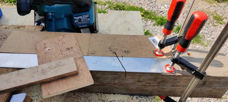
barclamps_flat_bar_angled_cut_jig_800.jpg


The side pieces are a little more complicated in that they have an angled face. These were cut with two jigs: the one described at the top of this post and the one in this photo. The one shown in this photo makes an angled cut at the right distance from the (already square) end of the bar. The remaining piece is then inserted into the first jig (against a stop) and cut off square to make a second angled piece.
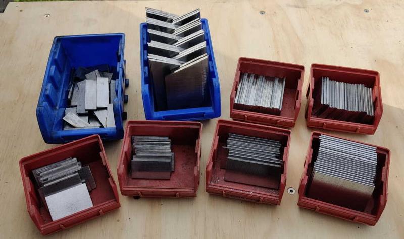
barclamps_flat_bar_piles_of_bits_800.jpg


This photo shows all of the parts that were cut up in this way. There are still about 30 more to pieces to cut: I was convinced I'd put all the bits of steel through the citric bath to remove the mill scale, but apparently I missed one. Ah well...
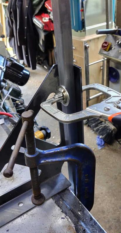
 
Today was a bit of a bonus day: I had convinced myself I would achieve nothing today as most people I've spoken to have felt rough the day after their first AstraZeneca Covid jab, but I seem to have escaped without any ill effects, so I could spend the day in the workshop instead of bed!

I decided to weld the inserts into the bars first. The welds are relatively straightforward, but slightly awkward due to the length of the bars (and the relatively short length of my bench!)

barclamp_bars_clamped_vertically_800.jpg


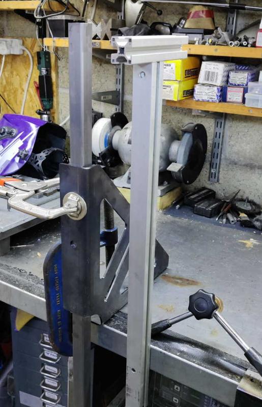
As the bars are too long for my metalwork bench, I decided to weld the inserts in with the bars held vertically. To support the bars for welding, I used a G-clamp to hold a welding square to the edge of my bench and then held each bar in place with a C-clamp. The advantage of the C-clamp (a wide jawed variant of a mole grip) here is that, once adjusted, it's very quick to unclamp one bar and clamp up the next.

barclamps_bars_vertical_with_arm_support_800.jpg


barclamps_bars_diagonal_for_insert_welding_800.jpg


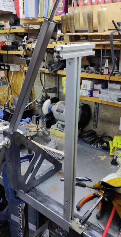
One disadvantage of having the bars held vertically is that it means that I'm working a long way off the bench. To make this more comfortable, I used my welding arm support with an extra bit of aluminium extrusion attached to the end. For the really long bars, I held them diagonally, but using the same welding square to support them.

barclamp_bars_holding_insert_for_tacking_800.jpg


barclamps_insert_tacked_into_place_800.jpg


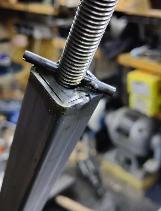
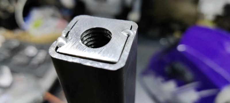
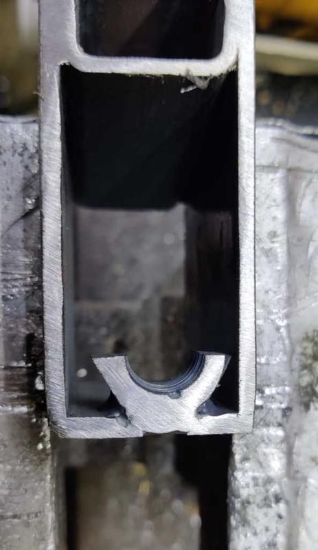
The other disadvantage of vertical bars is that there's a risk of the insert falling down into the bar. To stop this from happening, I cross-drilled an offcut of M12 threaded rod and inserted a roll-pin. This can be inserted into the threaded insert and dropped into the end: the roll-pin stops the insert from falling. The insert can then be tack-welded in place, the threaded rod removed and the welding completed. I made sure I placed the tack welds close to the roll-pin but on the side that is clockwise to the threaded rod. That meant that, as the threaded rod was turned anticlockwise to remove it, the roll-pin had risen up as far as possible to give it the best chance of clearing any bulge caused by the tack welds.

barclamps_bars_milling_end_faces_before_800.jpg


barclamps_bars_milling_end_faces_after_800.jpg


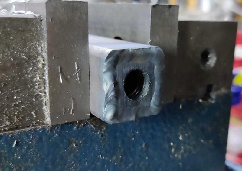
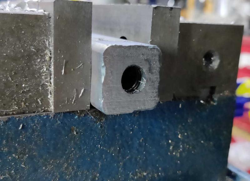
I'm not sure if this step was really necessary, but I decided to clean up the end faces of the bars. I did this on the milling machine as I have one and it seemed easy, although there are plenty of other approaches I could have used (or I could have just not bothered). The advantage of doing this is that it gives a nice flat surface for the end plate to bear on when the screw is tightened.
 
barclamps_welding_half_nut_to_end_of_threaded_rod_before_800.jpg


barclamps_welding_half_nut_to_end_of_threaded_rod_after_800.jpg


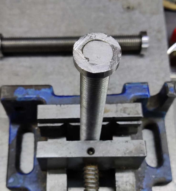
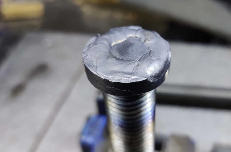
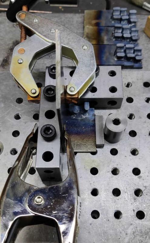
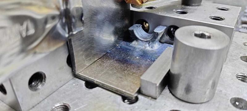
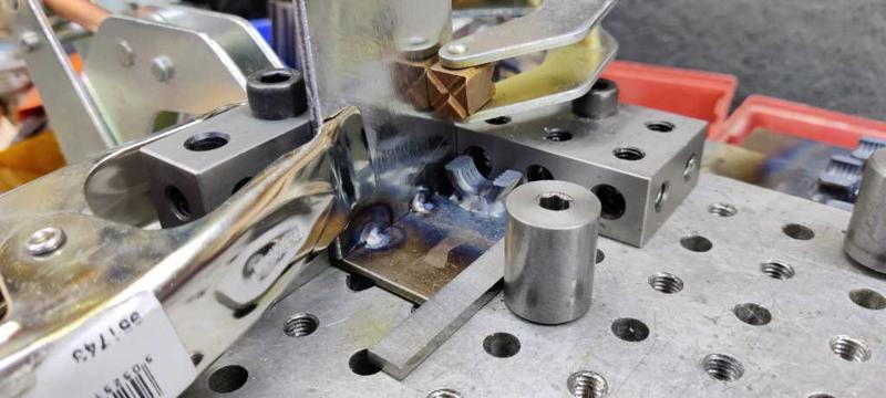
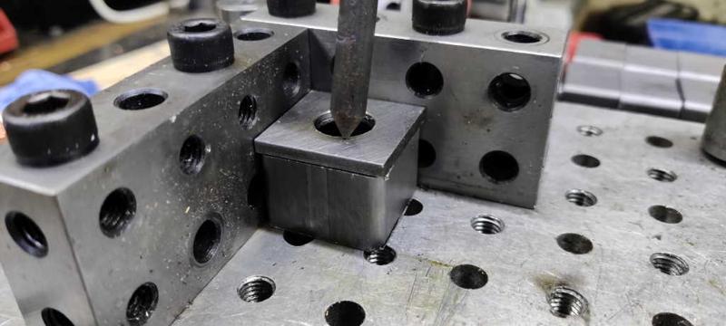
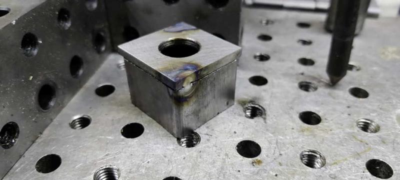
The next job was to weld one half of each split M16 nut onto the end of a bit of threaded bar. The other half will be welded in place after passing through the hole in the rear plate of the screw jaw, but I thought I'd get this one done in advance.

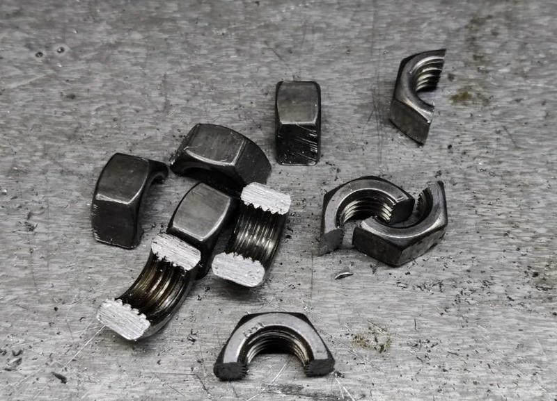
barclamps_hacksawed_m12_nuts_800.jpg


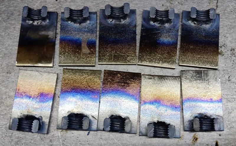
The first welding job for the sliding jaws is to fix half an M12 nut onto a piece of 3 mm × 31 mm × 50 mm steel bar. The nut (which was cut in half with a hacksaw after coming out of the citric acid bath) needs to be at the end of the flat bar and (more importantly) needs to be aligned with the flat bar.

barclamps_nut_alignment_jig_1_800.jpg


barclamps_nutalignment_jig_2_800.jpg


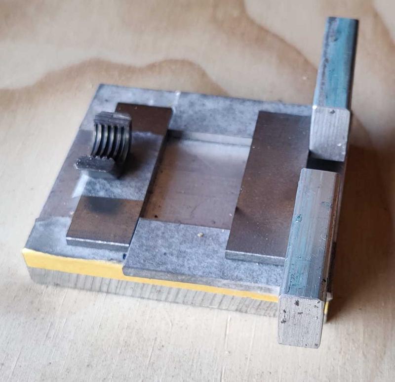
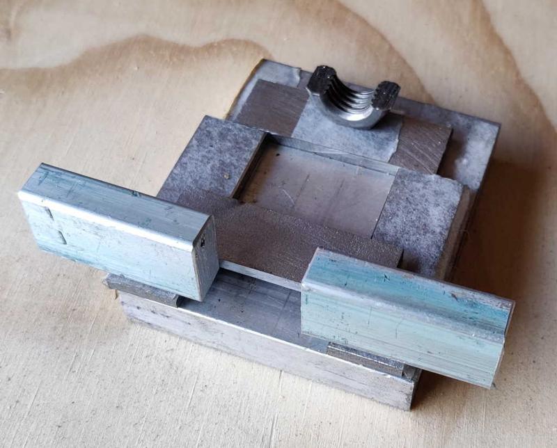
The photos above show the jig I made to help with this process. It was made out of various offcuts I had lying around, hence the slightly strange sizes of pieces. The base plate is aluminium, the thin flat bar pieces are offcuts of 3 mm steel and the "wings" that support the side of the nut are aluminium. It's held together with double-sided tape.

barclamps_nut_alignment_jig_loaded_800.jpg


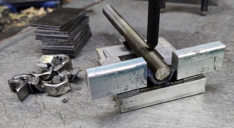
This photo shows how it is used. The piece of flat bar gets slid into the jig as far as it will go (it slides easily as the spacer pieces are the same thickness and there's the additional thickness from the double-sided tape). A half-nut is placed in the pocket and an offcut of M12 threaded rod dropped into both half-nuts. This makes sure that the half-nut is aligned with the axis of the flat bar. My welder's third hand holds the threaded bar down and the half-nut can be tack-welded in place. It's then removed from the jig and fully welded.

barclamps_half_nuts_welded_in_place_800.jpg


With the jig made, I was able to tack weld all of the pieces in about 20 minutes and be confident that they were all in the right place. I did have to be careful to ensure I didn't melt the thread at all as there's no way I can pass a tap through the thread to clean it up if I get it wrong!
 
That's really neat and thorough work, Dr Al.
 
I’m confused dr al
I get the m12 half nut bit but this
“The next job was to weld one half of each split M16 nut onto the end of a bit of threaded bar. The other half will be welded in place after passing through the hole in the rear plate of the screw jaw, but I thought I'd get this one done in advance.”
Eludes me and also I could not see it on your cad model.
Fascinating thread!
Bob
 
9fingers":3qg9rr4v said:
I’m confused dr al
I get the m12 half nut bit but this
“The next job was to weld one half of each split M16 nut onto the end of a bit of threaded bar. The other half will be welded in place after passing through the hole in the rear plate of the screw jaw, but I thought I'd get this one done in advance.”
Eludes me and also I could not see it on your cad model.
Fascinating thread!
Bob

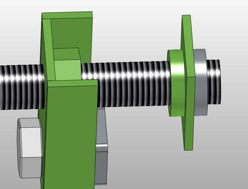
Glad you're enjoying the thread. The CAD model doesn't make it especially clear, but you can see the parts in this image (which has lots of the other bits removed):

barclamps_model_jaw_mover_800.jpg


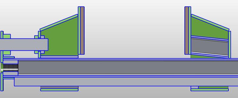
and this image (which is a cross-section with all the bits visible):

barclamps_cross_section_800.jpg


The threaded rod (grey block near the top-left of the cross-section) goes through a nut on the end plate. It then passes through the back plate of the screw jaw (green plate in the top image) with half a rounded-off M16 nut either side of the plate (one shown green, one shown grey). The half nuts are welded to the threaded rod, but nothing is welded to the plate. The idea is that the threaded rod can spin freely in the plate but will push and pull the plate back and forth as you turn the threaded rod in the end plate's nut.

The one I've welded in place so far is the one shown in grey in the images above.

You can see Neil's version 3 minutes into the video: https://youtu.be/P0wLjQqf-zM?t=180

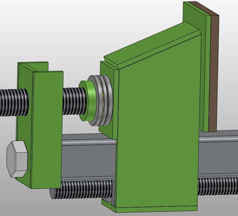
This part of the assembly is where the thrust bearing you suggested might go, something like this:

barclamps_model_screw_jaw_with_thrust_bearing.jpg

Does that make sense?
 
OK Gotcha!
A mix up on the subtleties of split nut Vs half nut. The text relating to the "threaded round bushes" you call split nuts, were next to a photo of hex nuts cut across their diameter.

I am enjoying the thread and almost want to start making some myself even though I've got a tolerable selection of bar and pipe clamps.
I do have about half dozen sash cramps in various states of disrepair/parts missing so might get my hot metal glue out and make the parts needed to make them usable.

Bob
 
9fingers":nk6rnrtw said:
OK Gotcha!
A mix up on the subtleties of split nut Vs half nut. The text relating to the "threaded round bushes" you call split nuts, were next to a photo of hex nuts cut across their diameter.

Ah, good point - I'd started calling them "split nuts" to distinguish them from the half nuts, but maybe it's not that clear.
 
Dr.Al":2vcqvubu said:
9fingers":2vcqvubu said:
OK Gotcha!
A mix up on the subtleties of split nut Vs half nut. The text relating to the "threaded round bushes" you call split nuts, were next to a photo of hex nuts cut across their diameter.

Ah, good point - I'd started calling them "split nuts" to distinguish them from the half nuts, but maybe it's not that clear.

Even the engineering fraternity cause confusion over nut nomenclature.
To a fixings supplier a half nut is a thinner than standard nut (aka a full nut). However the split nut used to disengage a lathe leadscrew is commonly known as a half nut too.

Bob
 
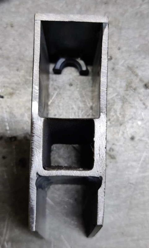
I started today by cutting up all the remaining bits of bar and some short lengths of 25 mm × 25 mm × 2 mm box section that sit inside the sliding jaw.

barclamps_model_chamfered_pieces_800.jpg


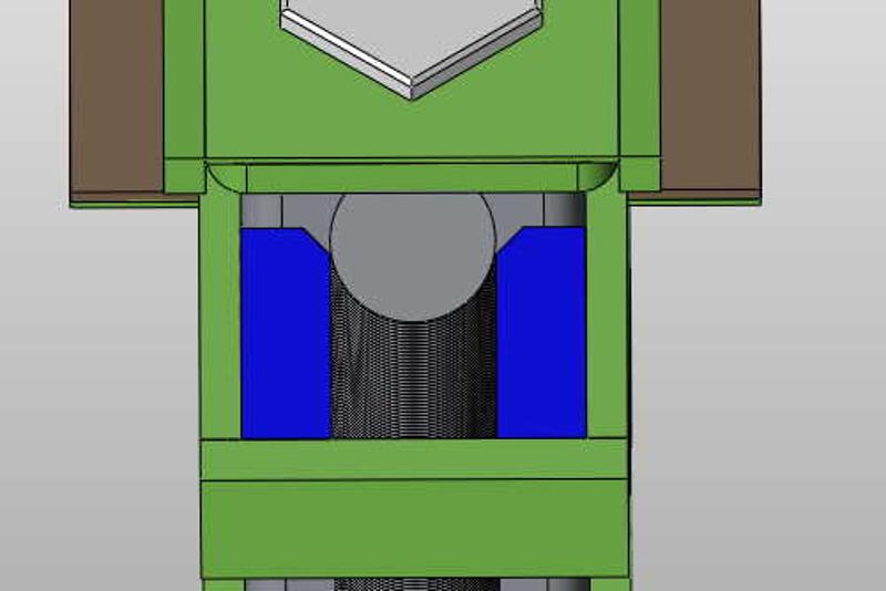
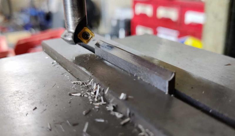
The pieces shown in blue in this image are shown as two single pieces, 6 mm × 15 mm × 50 mm. As I'm making everything else out of 3 mm flat bar stock, I'm making each of these out of two pieces, each 3 mm × 15 mm × 50 mm. The chamfer you can see at the top of each part is to give clearance for the weld beads attaching the M12 threaded rod to the box section bar.

barclamps_milling_chamfer_800.jpg


On the prototype, I cut this chamfer using a hand file, but given I've got rather a lot of them to do, I decided it would be quicker and easier to use this little chamfering end mill I picked up at the Bristol Model Engineering Exhibition a few years ago. With the home-made X-axis power feed on my milling machine, this dealt with all the chamfers very quickly.

barclamps_hole_in_end_cap_800.jpg


barclamps_hole_in_screw_jaw_rear_face_800.jpg


barclamps_holes_in_end_plate_800.jpg


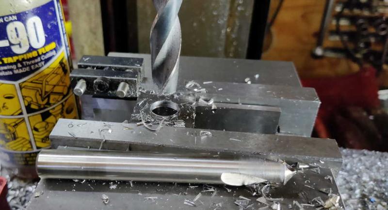
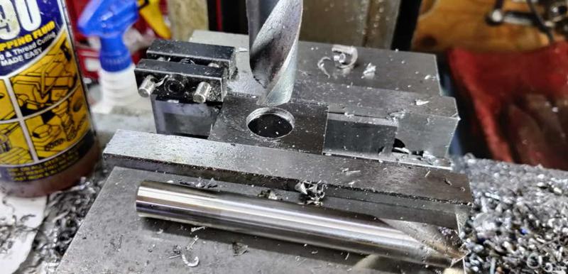
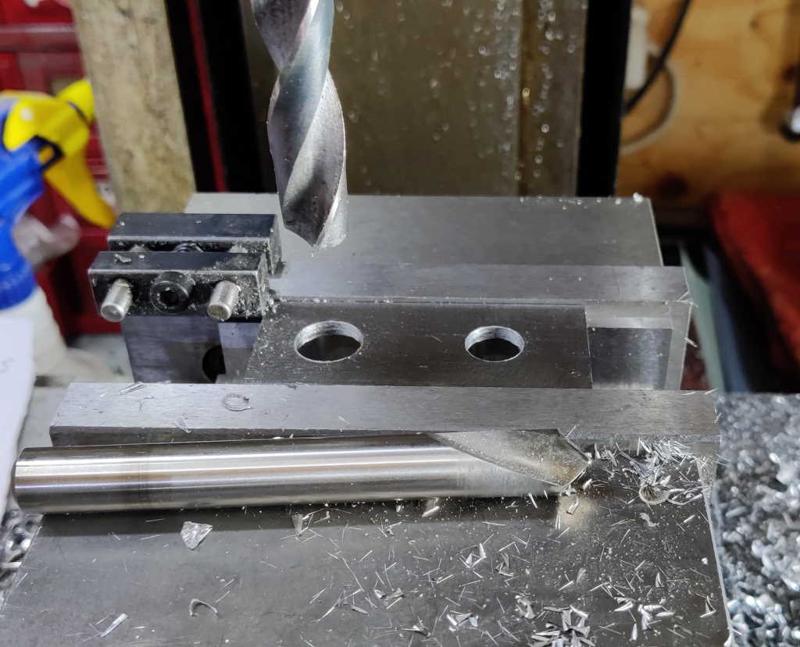
While I was on the milling machine, I decided to drill all the holes in the various plates (the first photo is the hole in the end cap, the second is the hole in the rear of the screw jaw through which the threaded rod passes and the third photo is the end plate with one hole to attach it to the bar and one hole for the M16 threaded rod to go through). On the prototype I drilled these holes on the drill press, but the milling machine is much more capable and the X-Y table combined with the stop (for repeatable positioning of parts in the vice) makes it easy to get the holes in about the right place. None of the hole locations are that critical: they're deliberately oversized (14 mm for 12 mm screws and 18 mm for the M16 threaded rod) to allow for parts moving when welding.

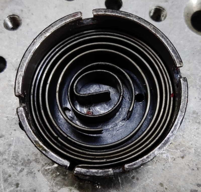
The only thing that made the process a bit more awkward was that the quill return spring on my milling machine snapped part way through the process:

barclamps_broken_spring_800.jpg


Thankfully it didn't stop me from doing the drilling, I just had to return it to the top by hand and then lock the quill up after each operation. Spare springs seem to be readily available and not too expensive, so that's a relief!
 
9fingers":1p0tml1y said:
Dr.Al":1p0tml1y said:
9fingers":1p0tml1y said:
OK Gotcha!
A mix up on the subtleties of split nut Vs half nut. The text relating to the "threaded round bushes" you call split nuts, were next to a photo of hex nuts cut across their diameter.

Ah, good point - I'd started calling them "split nuts" to distinguish them from the half nuts, but maybe it's not that clear.

Even the engineering fraternity cause confusion over nut nomenclature.
To a fixings supplier a half nut is a thinner than standard nut (aka a full nut). However the split nut used to disengage a lathe leadscrew is commonly known as a half nut too.

Bob

Clear as mud :lol: :obscene-drinkingbuddies:
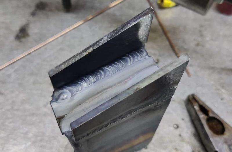
 
barclamps_fitting_first_side_to_sliding_jaw_800.jpg


barclamps_fitting_first_side_to_sliding_jaw_close_up_800.jpg


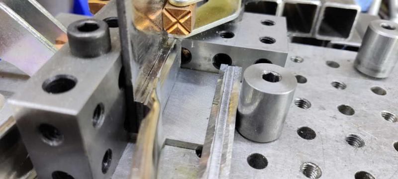
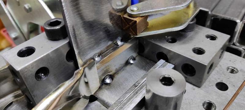
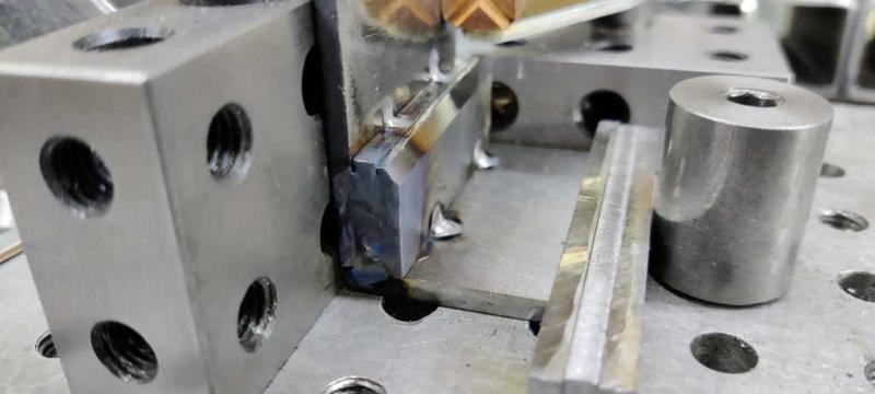
This afternoon I started work on tack welding the frames together. It's amazing how long everything takes when you have to multiply each job by 10! The photos above show the jig I used to attach the first side to the base of the sliding jaw. It's based on an aluminium fixture plate I made a few years ago. The fixture plate has holes (alternately reamed 8 mm and tapped M8) on a 20 mm grid, so I attached a couple of 20-40-80 blocks to use as reference edges. An eccentric screw clamps the base into place and then a spring clamp holds the side of the frame in place to make it easier to attach the cantilever clamp to hold it more firmly.

barclamps_sliding_jaw_first_tacks_800.jpg


For now I just did a couple of tack welds along the bottom edge to join the pieces together.

barclamps_screw_jaw_ready_for_first_tacks_800.jpg


barclamps_screw_jaw_first_tacks_800.jpg


For the screw jaws, I used the same fixture, but put the small ledge pieces in at the same time. I had to use a different spacer between the base plate and the eccentric screw as the base plates are a bit narrower on the screw jaw. The plate is intended to be 3 mm × 31 mm × 50 mm, but I ran out of 50 mm wide plate so I made these out of 30 mm plate - hence they're 3 mm × 30 mm × 50 mm. The difference shouldn't matter as it just means there's a gap on the outer edge on one side: that gap can be filled up with a weld bead. The bottom two tacks in the second photo were done with filler rod to make a decent joint; the top two were done without filler to minimise the size of the weld: ideally I want these welds to sit within the radius of the box section that will slide along here.

barclamps_screw_jaw_first_spacers_end_weld_800.jpg


After tacking the pieces together, I took the spring clamp off and welded the spacers together and to the frame on one end. I did this without filler, just because it was quick and easy to do so. Amazingly I didn't melt my 20-40-80 block when welding any of the frames!

barclamps_jaw_frames_first_side_on_800.jpg


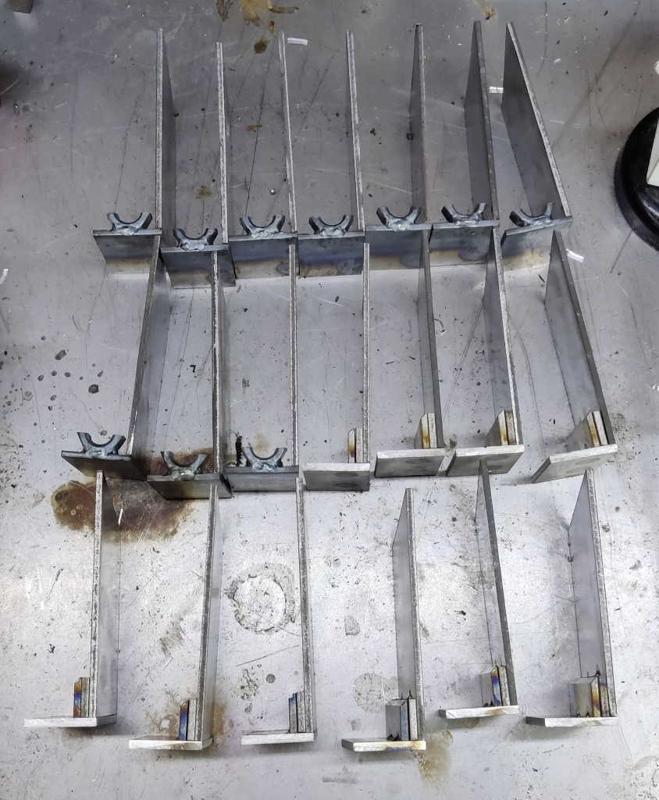
This photo shows what it all looked like with one side of each frame tacked in place.

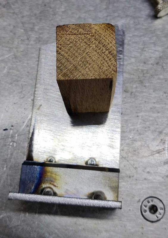
barclamps_frame_wooden_jigs_800.jpg


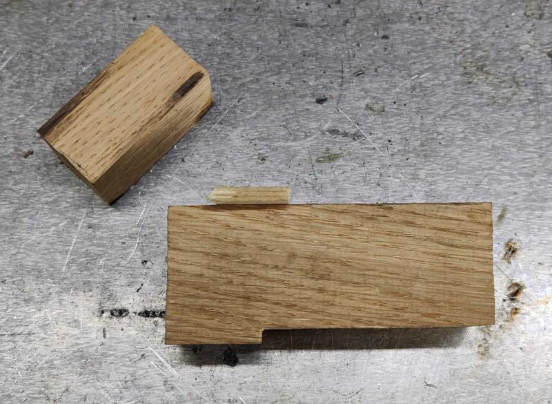
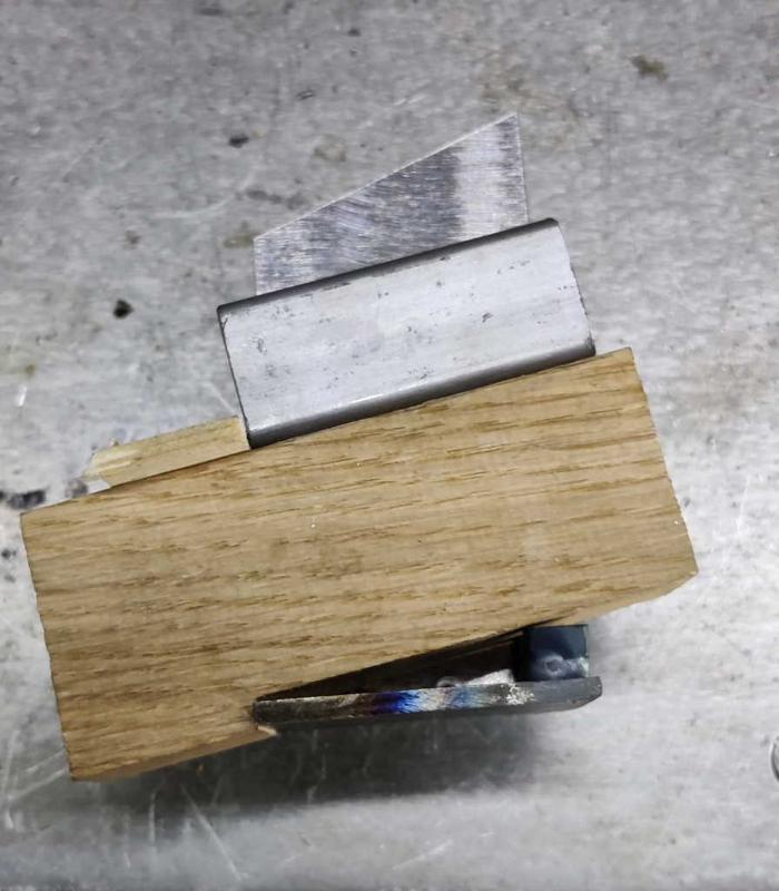
These two bits of wood were the "jigs" I used to complete the frames. They started out as one piece of oak that I hand-planed down to 25.5 mm thick. I then separated and shaped the two pieces. One is a 25.5 mm rectangular prism with one chamfered edge; the other has a ledge on one side and a scrap of pine nailed to the other side to help with assembly. When I made the prototype, I spent ages worrying about what angle to use for the sliding jaw assembly. In the end I realised it really doesn't matter that much - there's plenty of opportunity to tweak it after welding it together (filing the back to get it to sit horizontally and lowering the jaw piece to get the right drop height).

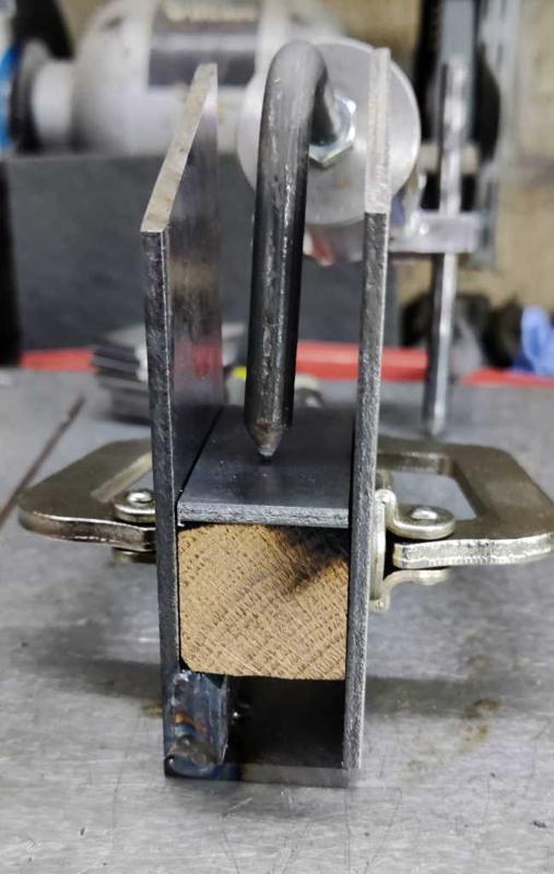
barclamps_sliding_jaw_frame_jig_in_use_800.jpg


This photo shows how the jig helps with assembly. In practice, I don't fit the internal bit of box section until the frame sides are clamped together (it's thinner than the wood so can easily be slid into place), but I thought it helped for the photo. The box section will be ground down to match the width of the frame after everything is welded together.

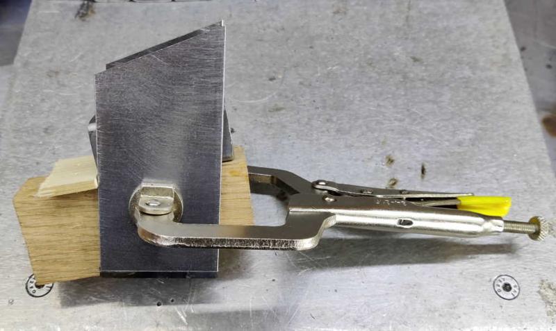
barclamps_sliding_jaw_frame_clamped_800.jpg


I used a C-clamp to hold the frame together to weld it. The box section is only held in by gravity here, but that's good enough to get some tack welds on the corners.

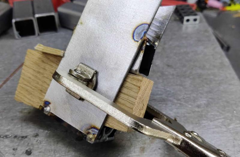
barclamps_sliding_jaw_frame_tacked_800.jpg


This is what a sliding jaw looks like after tack-welding it together. At this point the C-clamp can be removed and the wood "persuaded" to come out by tapping it with a hammer. I'll come back to doing some proper welds later.

barclamps_screw_jaw_jig_chamfer_800.jpg


The screw jaw "jig" has a chamfer on one corner. That's there just to make sure it clears the tack welds on the frame and is about the same size as the radius on the corner of the box section it's emulating.

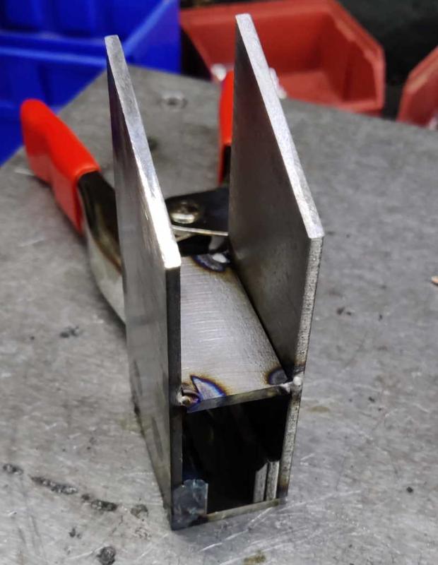
barclamps_screw_jaw_frame_clamped_800.jpg


This shows the "jig" for the screw jaw frame being used. It's simply a spacer that ensures that the box section will slide easily through this bit of the screw jaw. The top plate is a lot lighter than the box section used for the sliding jaw, so I held it down with my welder's third hand.

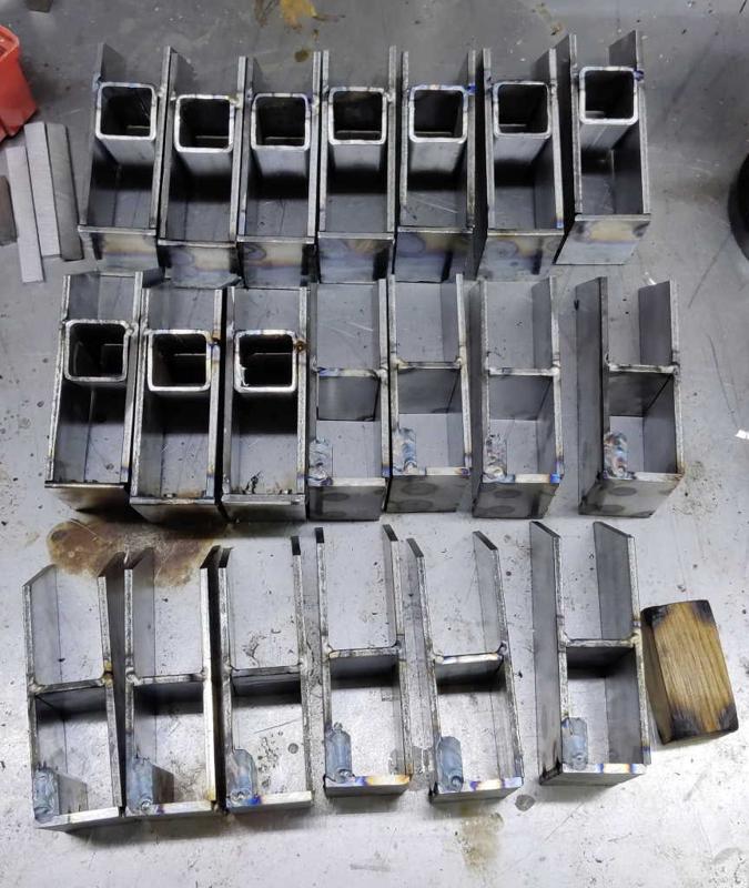
barclamps_jaw_frames_without_second_spacer_set_800.jpg


This shows all the frames having been tack-welded together.

barclamps_screw_jaw_second_spacer_set_800.jpg


The last bit of preparation welding was to attach the other pair of ledge pieces to the screw jaws. Like the first ones, I did this without filler rod for speed and ease. They were held in place with spring clamps, so were quick to put together and doing all ten screw jaws took very little time.

barclamps_jaw_frames_with_second_spacer_set_800.jpg


This photo shows the jaw frames with the second set of spacers added.

That's it for today; I'll have to go back and finish welding all of the frames properly (rather than just having tack-welds everywhere), but I thought it was time to call it a day.
 
barclamps_welded_sides_800.jpg


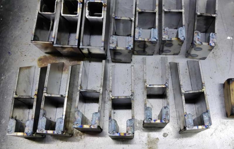
The next job was to finish the welding on all the frames. With everything tack-welded in place, this was a relatively quick process. Having said that, with twenty frames to tack, it still took almost two hours of pretty much constant welding (I didn't even lift my helmet visor once in that two hours!)

barclamps_welds_top_of_box_800.jpg


barclamps_welds_in_screw_jaws_800.jpg


When Neil Paskin made his clamps, he drilled a series of holes in the sides of the frames so that he could plug-weld through the holes to join the side pieces to the inner pieces. When I made the prototype, I did the same thing, but having made it I decided that access through the top was good enough that I could make a good enough joint without having to bother drilling all those holes.

barclamp_frames_welded_and_ground_800.jpg


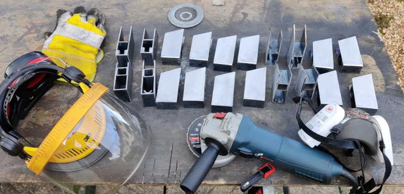
Once the frames had cooled down, I took advantage of the fact that the sun was shining and took the sliding jaws outside to grind off the excess box section with a 40 grit flap wheel in an angle grinder. I then gave the sides a quick once-over with an 80 grit flap wheel.
 
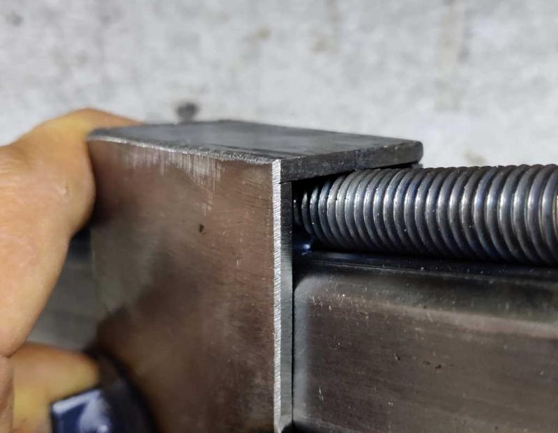
Before carrying on with any welding, I did some testing of the fit of all the jaw frames on the prototype bar (I haven't welded the threaded rod to the final bars yet). The aim of this was to check two things:
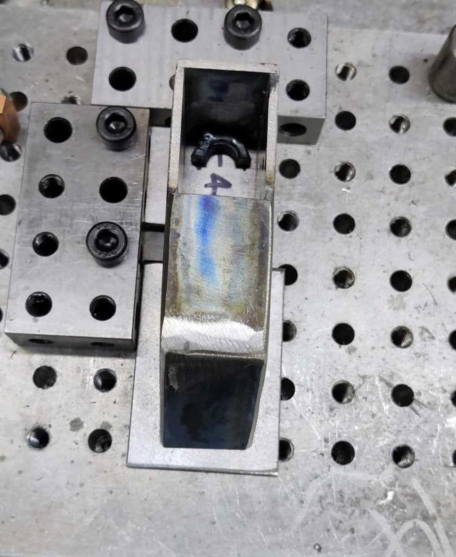
  1. The jaw frames should move freely along the whole length of the bar.
  2. In the case of the sliding jaw, the jaw should sit parallel with the bar when the half-nut is engaged with the thread. If it sits with the rear edge high, a small amount can be filed off the lowest edge of the short bit of box section welded into the frame to sort this out. If it sits with the rear edge low, the rear face plate for the jaw can be mounted a little lower than the box section to sort it out.

This didn't go well...

None of the screw jaw frames would slide on to the box section (even with a bit of box section that didn't have the threaded rod attached, so it wasn't due to the ledges being too wide). Somehow, the side plates had ended up slightly too close together, not leaving enough clearance for the box section to run smoothly through. I don't really understand why this happened as the "jig" (bit of wood) I used was the same one I used on the prototype and that worked fine. The only vague idea I've had is that the heat of welding the prototype caused the wood to shrink by enough to make a difference. The frame sides looked to be parallel (and needed a fairly even amount taking off the side of the frames), so it's not as if they've bent inwards at one end and closed up because of that. Also weirdly, the sliding jaw frames (which used a jig cut from the same piece of wood - after planing to size) slid on the box section perfectly.

power_file_800.jpg


Anyway, at least it was solvable, it just made me very grateful to have this little "power file". I'm not sure what I'd do differently if I made them again; although checking the frames after tack-welding would have given me a chance to fix the problem more easily.

The second check involved checking that the sliding jaws sat parallel with the bar when the half-nut is engaged with the thread. Six of the jaw frames were absolutely spot on. Three of them tilted forward a bit (of which one had another problem) and one tilted back a little. The one that tilted back didn't really need anything doing to it: when the back piece is fitted it can be fitted a little lower than the bottom of the box section and it will support the frame.
barclamps_sliding_jaw_filed_down_insert_800.jpg


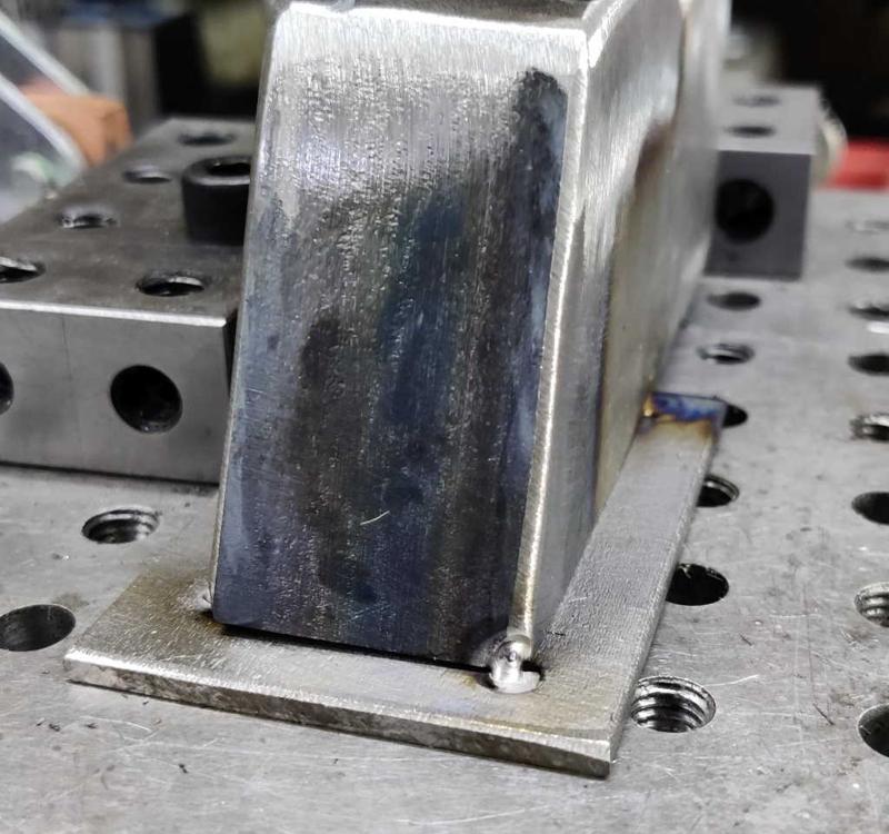
For the three that tilted forward a bit, I had to file down the rear corner of the angled box section piece. As the angle of the box section is quite steep, there wasn't much material that had to be removed and I just did this with a hand file.

barclamps_sliding_jaw_with_nut_in_wrong_place_800.jpg


One of those three had another problem that had to be sorted first. Somehow, its nut had ended up off-centre. I've no idea how that happened. Maybe it was the last one I welded and the double-sided tape I'd used to hold the jig together had started to perish, but I'm really not sure. Bearing in mind that I'm making 10 frames with the aim of getting 8 good ones, I seriously considered just chucking it in the bin and forgetting it, but in the end I got the Dremel out and cut the nut out.

barclamps_sliding_jaw_bar_as_nut_alignment_800.jpg


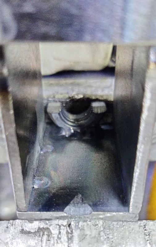
I could then use the prototype bar as an alignment jig and was able to tack the nut in place. I then removed the bar and welded all the way along the front edge and (with the TIG torch plunged deep inside the frame and pretty much out of sight) I also managed to get a couple of tack welds on the back the of the nut.
 
With all the jaw frames sorted, I could get on with welding. I started by fitting all the back plates. Note that, in the case of the screw jaw, this is a different sequence to the one used by Neil Paskin - he attached the M16 threaded rod to the plate before welding it into the screw jaw. I decided that switching the order around would make it easier as the plate doesn't have a bit of rod flapping around making it awkward to weld.

barclamps_sliding_jaw_back_piece_feeler_800.jpg


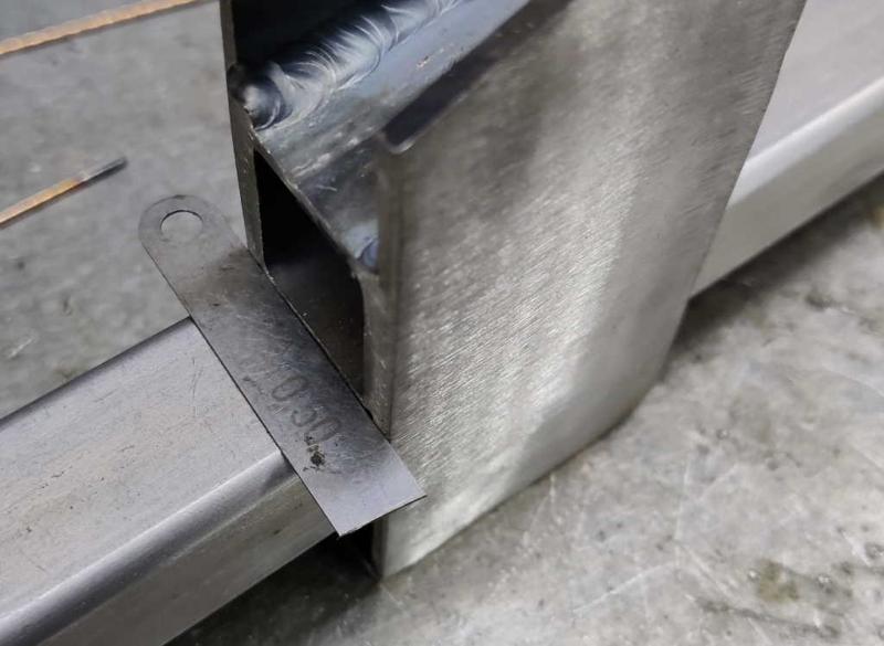
I started with the sliding jaws. For all but one of these, I placed them on the prototype bar (with the half-nut engaged and the jaw frame sitting parallel with the bar) and used a small piece of feeler gauge as a spacer. I've got loads of these little pieces as I bought three super-cheap feeler gauges about 10 years ago and cut them up for use as shim stock when using the four-way tool post that came with my mini-lathe. Now I just use them for odd jobs like this.

barclamps_sliding_jaw_back_piece_clamped_and_tacked_800.jpg


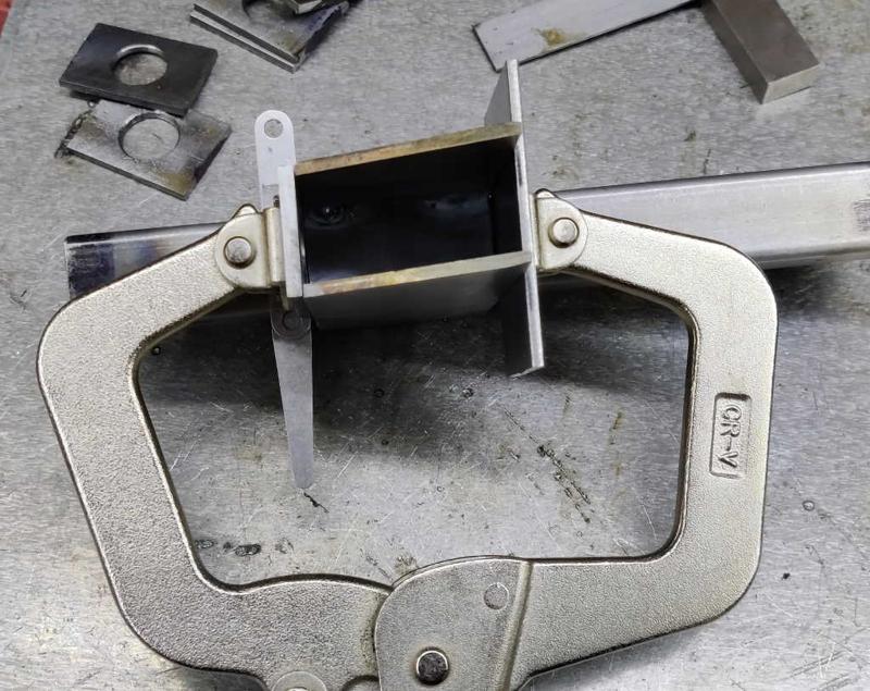
The back piece could then be placed on top of the feeler gauge stock, clamped in place and then tack welded. After the first few, I switched from using the cantilever clamp shown in this photo to using a C-clamp as the pliers-style action of the C-clamp is much quicker and easier one-handed.

barclamps_welded_back_piece_for_sliding_jaw_800.jpg


After putting two tacks at the top and one on the side not covered by the clamp, I took the clamp off, took the frame off the prototype bar and welded up each side.

One of the frames (the one that tilted backwards) had to be dealt with slightly differently. For this one I didn't use the feeler stock and, after lightly clamping the back in place, tapped the back down until the frame sat parallel with the bar. I then tacked and welded as before.

barclamps_clamping_back_piece_for_screw_jaw_800.jpg


For the screw jaw the approach was very similar. The only differences were:

  1. With the sliding jaw, when in motion the back is lifted up and away from the bar. Therefore, the back piece can be safely placed very close to the bar. For the screw jaw, that's not the case so I used a thicker 1.5 mm spacer made up of two pieces of feeler gauge stock.
  2. The screw jaw doesn't have the box section all the way through, so I used a spare piece of steel on the front to give the clamp something to bear on.

You can see the clamping arrangement (with the C-clamp, which I used from the start on these jaws) in the photo above.

barclamps_welded_back_piece_for_screw_jaw_800.jpg


As with the sliding jaw, after removing the clamp and removing the frame from the prototype bar, I welded the back piece along both edges.

barclamps_all_backs_on_800.jpg


This photo shows all 20 frames ready to have their tops fitted.
 
Lovely welding.

I did a one-day welding course a couple of years ago and subsequently bought myself a welder. I really enjoy it but could do with more practice.

I was delighted the other day when a steering-related component on my ride on mower broke and I was able to repair it with the welder. It gave me a lot of satisfaction to stick some metal together and get the thing back in action. I was also able to tell my wife that the welder has now already paid for itself :eusa-whistle:
 
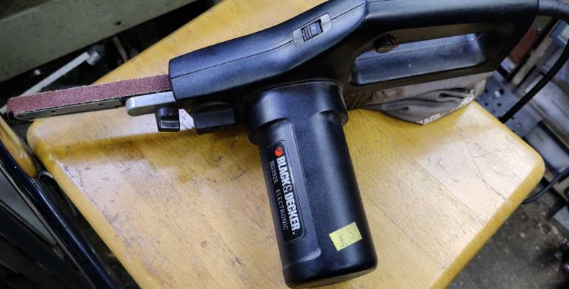
This is excellent stuff, Dr Al. I admire your patience, and your precision. Oh, and I've got one of those B&D powerfiles, but bright reddy-orange.
 
NickM":264pi7p1 said:
Lovely welding.

I did a one-day welding course a couple of years ago and subsequently bought myself a welder. I really enjoy it but could do with more practice.

I was delighted the other day when a steering-related component on my ride on mower broke and I was able to repair it with the welder. It gave me a lot of satisfaction to stick some metal together and get the thing back in action. I was also able to tell my wife that the welder has now already paid for itself :eusa-whistle:

Thanks. I really enjoy (TIG) welding (I hate the spatter, fumes & need to clean up flux of arc welding): I find it a very relaxing thing to do. I'm not sure anything I've done has come close to paying for the welder though! :eusa-whistle:

Mike G":264pi7p1 said:
This is excellent stuff, Dr Al. I admire your patience, and your precision. Oh, and I've got one of those B&D powerfiles, but bright reddy-orange.

Thanks Mike. I inherited the power file from my father-in-law (who got it at a car boot sale for £3). When I saw it I thought it would be rubbish & that I'd never use it, but it's come in really handy a few times now.
 
barclamps_cleaned_up_ready_for_top_800.jpg


Fitting the tops was a relatively straightforward process, although I had to skim a little bit of the top of some of the backs with a flap disc in an angle grinder: I think I'd cut the tops slightly longer than originally planned so they overlap with the back rather than butting up against them.

barclamps_holding_top_for_tacking_800.jpg


The exact position of the top pieces really isn't that important, so I held them in place with one hand while tacking one corner (without filler rod).

barclamps_top_welded_800.jpg


barclamps_top_welded_on_800.jpg


I could then tack the opposite corner and then weld round the three sides.

barclamps_all_tops_welded_on_800.jpg


Rinse and repeat.
 
barclamps_tidied_up_with_angle_grinder_800.jpg


I'd debated whether to leave the welded outer corners with the weld beads visible or round off the corners, but in the end I decided to give them all a quick go with an 80 grit flap disc in the angle grinder to round everything off nicely.

barclamps_screws_inserted_ready_for_jaws_800.jpg


The jaw pieces could then be fitted to the frames. In the case of the screw jaw frame, the threaded rod has to be inserted before attaching the jaws, but it doesn't need to be welded in place, so for now I've just hand-tightened the other split nut onto the threaded rod to hold it in the hole.

To choose a place for the jaws, there are a few options:

  1. Line up the bottom of the jaw piece with the bottom of the cross-piece (in the case of the screw jaw, this is the 3 mm × 25 mm × 50 mm plate and in the case of the sliding jaw this is the bottom edge of the internal box section). This has the disadvantage that the two jaws won't line up with one another, so it's probably best to trim one of the jaws down to match the top of the other. This was my approach for the prototype.
  2. Line up the bottom of the jaw piece of the sliding jaw with the bottom of the box section and then line up the bottom of the jaw piece on the screw jaw with the jaw piece of the sliding jaw.
  3. As per the previous option, but lower the jaw piece of the sliding jaw until it is at the lowest height that still allows the half-nut to disengage from the threaded rod.

The advantage of the last one is that the bottom of the jaw will be as close as possible to the box section (and parts are likely to be resting on the box section for clamping); the disadvantage is that when sliding it, there won't be two flat surfaces sliding together: it'll be two edges sliding on a flat surface. I don't think that's an issue, so I went with the last option. I did, however, lightly chamfer (with a flap disc in an angle grinder) the rear edges of the jaws to give a slightly smoother running surface.

To work out the position of the jaw pieces, I fitted a jaw piece to a sliding jaw and held it in place with a clamp. I checked whether the jaw could disengage and kept lowering the jaw until it couldn't any more. I then moved it back up until it could just disengage and measured the distance from the bottom of the frame to the bottom of the jaw piece. This worked out as 46 mm. I added a little bit for a safety margin and then cut a spacer to the resulting size: 48 mm. This could then be used as a reference when tacking the jaw pieces in place.

barclamps_jaw_tack_jig_800.jpg


This photo shows the jig I used to tack the jaws in place. It's based on the same fixture plate I used earlier in the project. The two 20–40–80 blocks give a right-angle reference. The two small blocks (one on top of another) are offcuts that happened to be about the right size to offset the body and get the jaw centred. They're held in place with double-sided tape and there needed to be two (actually one cut in half) due to the fact that the body is raised up by the thickness of the jaw. The spacer (marked with its size) sets the offset for the jaw relative to the base of the jaw frame.

barclamps_jaw_ready_for_tack_800.jpg


This shows one of the jaws sitting on the jig ready to be tacked in place. Hopefully this shows what all the bits are doing. With the body held down onto the jaw with my left hand, I placed a tack in one corner and then placed further tacks in the other three corners (it doesn't need to stay held in the jig for the other three tacks).

barclamps_jaw_tacks_800.jpg


This shows what the jaw looks like with the tacks done.

barclamps_jaws_tacked_800.jpg


So far, I've tacked all the jaws in place; tomorrow I'll weld round the three sides of the join to complete the frames.
 
Mike G":36bllnqe said:
:eusa-clap: Very impressive.

Thanks Mike. It feels like I'm getting there now (although I've still got the interesting task of attaching the threaded rod to bars that are much longer than my bench!)
 
9fingers":2soak163 said:
Dr.Al":2soak163 said:
Mike G":2soak163 said:
:eusa-clap: Very impressive.

Thanks Mike. It feels like I'm getting there now (although I've still got the interesting task of attaching the threaded rod to bars that are much longer than my bench!)

You needs some clamps for that Dr Al :lol:

Bob

:text-goodpost: :text-lol:
 
barclamps_one_jaw_welded_800.jpg


Last night I was lying in bed after midnight and feeling completely unable to get to sleep so in the end I got up and did a bit more welding. It really felt like I was getting in a rhythm by the end and I was really pleased with the welds on the last few jaws.

barclamps_all_jaws_welded_800.jpg


All the jaws have now been welded (except having looked at that photo, it looks like I missed one edge of one jaw somehow (well, it was 1 o'clock in the morning). That won't take long to sort out today.
 
barclamps_sliding_jaw_needs_filing_800.jpg


The last job to be done on the sliding jaw frames is a little bit of filing. As the sliding jaws run along the threaded rod, the rear corner of the jaw bounces in and out of the thread. This isn't actually a problem, but the movement can be made smoother with a bit of filing.

barclamps_sliding_jaw_filed_800.jpg


I used a half-round file and cut a small groove in the rear of the jaw. This makes the jaws move much more smoothly.
 
The next job was to weld the threaded bar to the rods.

barclamps_rod_alignment_jig_uncut_800.jpg


barclamps_rod_alignment_jig_cut_800.jpg


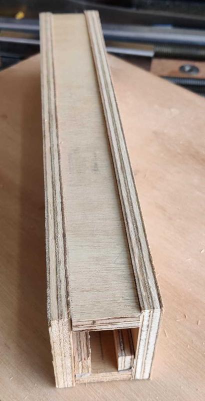
These photos show the jigs I made (based closely on the idea in the original video) to make sure the threaded rod is mounted centrally on the main box section bar. They were made out of a bit of 9 mm plywood, cut into strips and stuck together with double-sided tape. The short pieces in the middle that support the sides of the threaded rod are 6 mm thick (cut down from 9 mm on the table saw). I then cut the long jig into shorter pieces to make multiple jigs for holding in different places along the length of the bar.

barclamps_long_bar_welding_setup_closeup_800.jpg


These jigs worked well for the prototype but had some minor disadvantages. Being made of wood, they're non-conductive so the welding return current connection has to be attached via another method rather than through the jig and the bench. Also, they don't hold the threaded rod especially rigidly so there's a chance the rod could move off centre. I was planning to use the jigs again to make the final bars but it occurred to me that there was another option for a very effective alignment jig: the sliding jaws I've just made.

The next challenge was to find somewhere to put the bars to make welding the threaded rod relatively straightforward. The longest bars are considerably longer than my welding bench (and a bit longer than my woodworking bench: I'm not expecting to use the longer ones until after I've moved house and got a bit more space!). When I made the prototype, I placed the prototype box section bar on a couple of V-blocks on my bench. The V-blocks provided the current path (so I didn't have to mess around attaching the earth clamp to the bar itself) and also held the bar at the ideal angle for welding in the join between the rod and the box section. Sadly, this isn't practical with the long bars on my short bench!

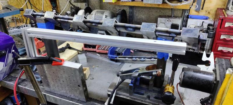
barclamps_long_bar_welding_setup_800.jpg


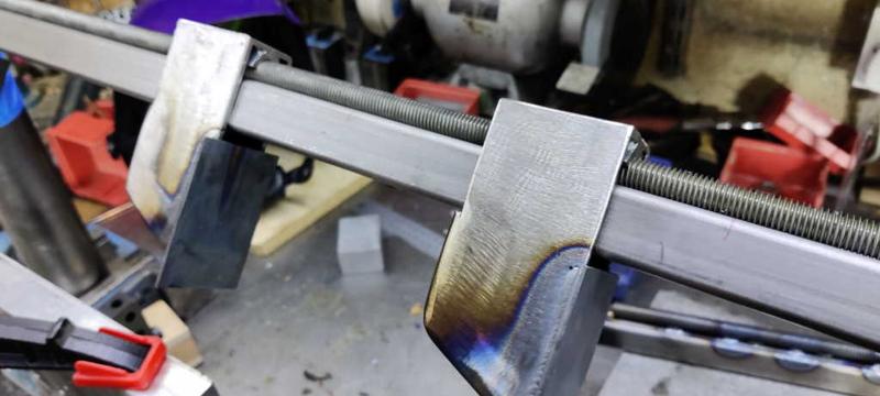
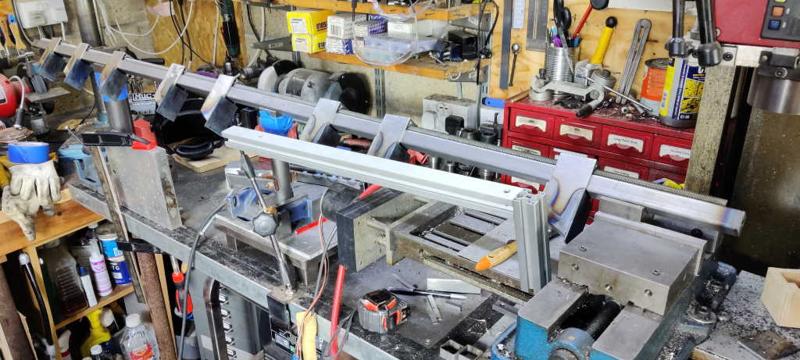
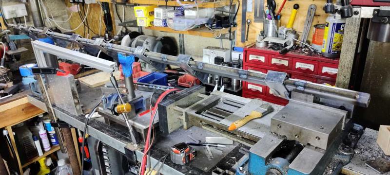
The photo above shows the set-up for the longest bars. There's quite a lot going on in this image (if you're looking at this on my website, you can click on the picture for a bigger image). On the right-hand side, the bar is supported in a V-block held in the milling machine vice. At the far end, there's another V-block sitting on the bench drill's table (which has been adjusted to be at the right height). In between are two further V-blocks, attached to some bits of bar stock with masking tape; each piece of bar stock is held in a vice and one has the return current clamp attached to it. My welding arm support is attached to the bench and supported on the milling machine's table to give me somewhere to rest. Over to the left, a block of aluminium is clamped to the bench so that when I've gone half-way along the bar, I can spin the welding arm support round and rest it on that block to do the next bit of bar.

barclamps_long_bar_welding_complete_800.jpg


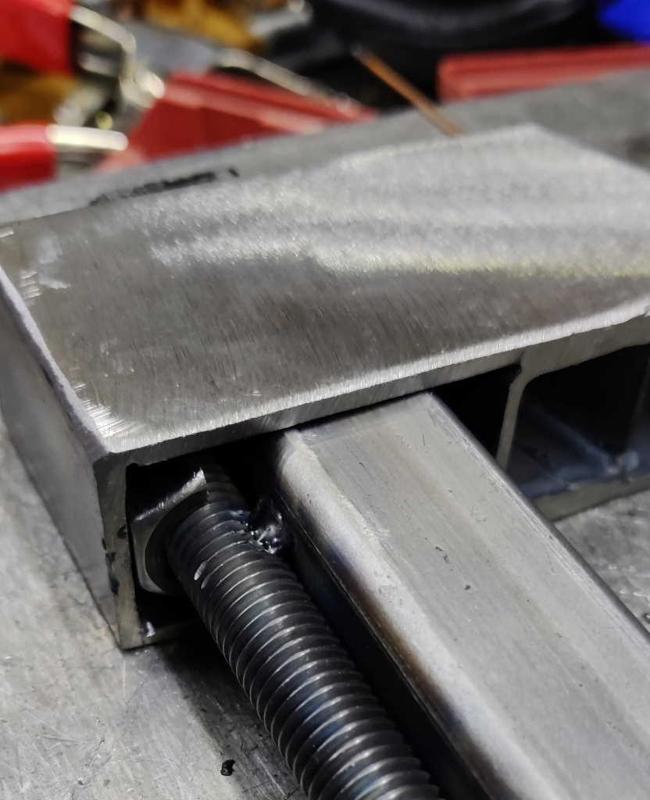
Although it really isn't important, I decided to try to space the welds relatively consistently along the length of the bars. To help with this, I used a crayon to mark every 150 mm along the bar. That doesn't result in them being evenly spaced relative to the ends, but it's good enough for me. When I made the prototype bar, I tacked both ends of the threaded rod and then did the beads along the sides of the threaded rod. That mostly worked, but the threaded bar ended up bending out of position (probably as a result of the threaded bar expanding with the heat). This time, I tacked one end and then worked my way along the bar (doing both sides of the threaded rod at each position before moving to the next position).

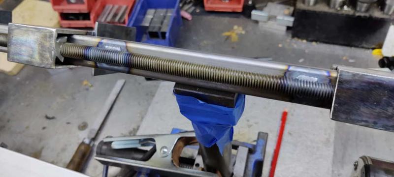
barclamps_bar_welds_closeup_800.jpg


This photo shows a close-up of a couple of the welds. You can also see the masking-tape holding the V-block in place.

To try to minimise the chance of corrosion, I did this welding straight after the threaded rod had been in the citric acid bath (to remove zinc). I took a bar out of the acid, gave it a blast with the air line to get rid of most of the moisture and then immediately put it on the jig to weld. I figured the heat from welding would get rid of any remaining moisture. After welding, I put the first bar aside while welding the second one; once the second bar was welded, the first bar had cooled down enough that I could brush some ACF50 onto the threaded rod to protect it from rust.

So far I've only welded the four long bars. I figured these would be most awkward so I'd start with them. They've distorted slightly, which I was expecting but didn't think I could do anything about. As the threaded rod cools, it'll shrink in length and pull the box section in slightly, causing the box section to bend towards the threaded rod. I'm hoping it'll be less severe on the shorter bars and also that it isn't enough to cause any actual problems when using the long ones. Time will tell.
 
barclamps_threaded_rod_on_shortest_bar_800.jpg


The shorter bars were (unsurprisingly) quicker and easier than the longer ones. This photo shows the set-up for the shortest bar length I've made. As you can see, I used the V-blocks mounted on bar stock that I'd used for the longest ones, but I didn't have to move the arm support during welding and didn't have to use the supports on the milling machine or bench drill table.

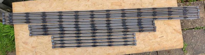
barclamps_all_bars_after_attaching_rod_800.jpg


This shows all of the bars with the threaded rod attached and ACF50 brushed on. The longest ones are 1880 mm, the middle length ones are 1200 mm and the short ones are 800 mm. In theory, the maximum clamping length should be about 150 mm shorter than those dimensions.


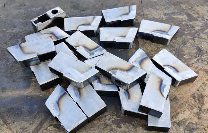
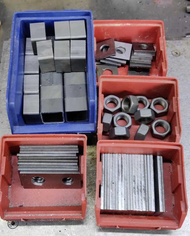
barclamps_remaining_pieces_800.jpg


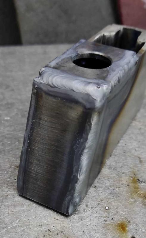
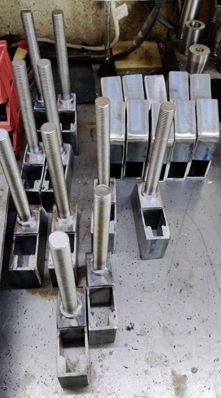
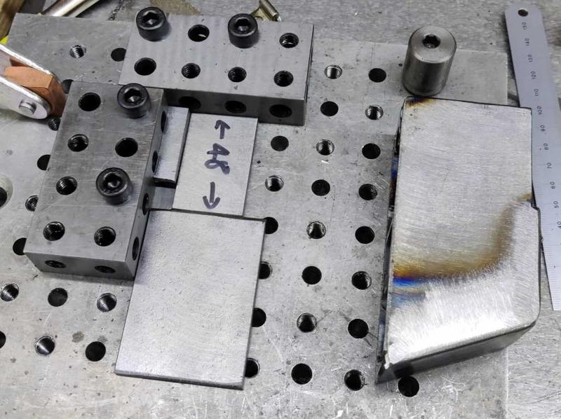
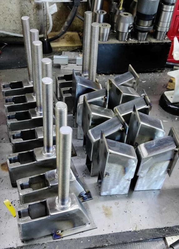
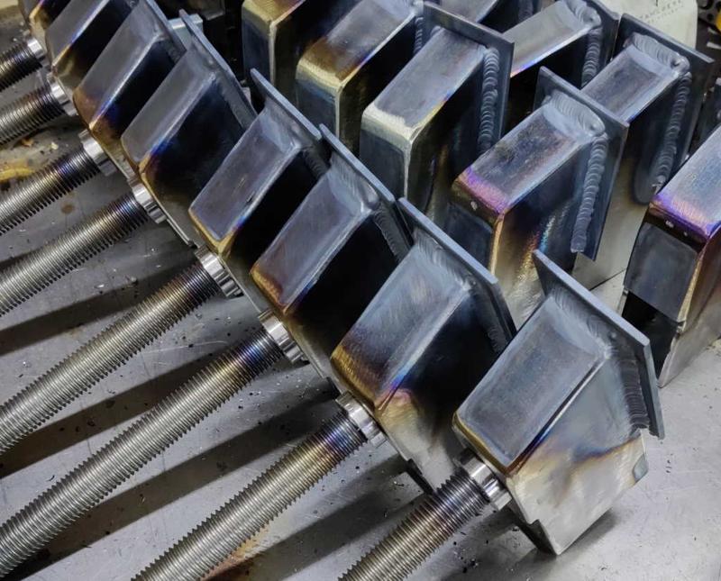
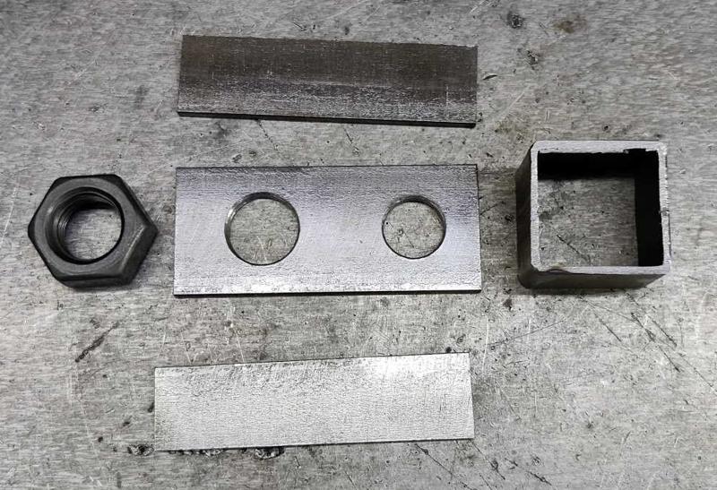
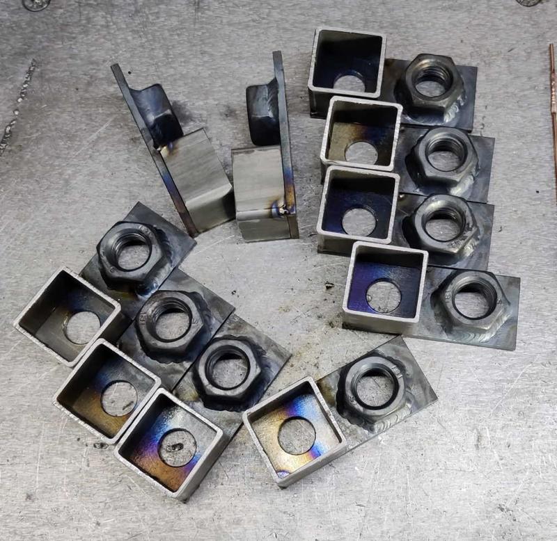
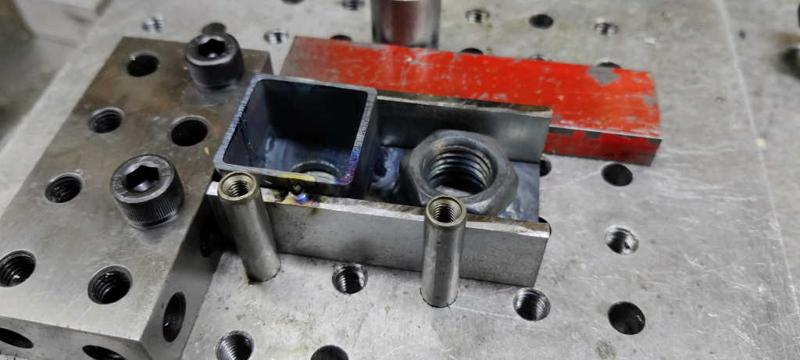
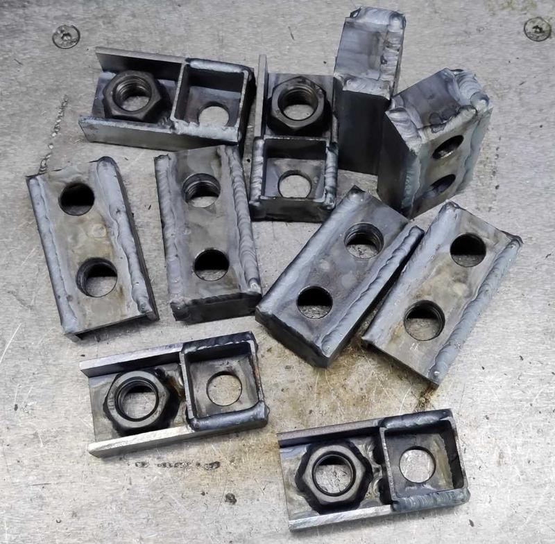
This photo shows the pieces that I have left to weld together (excluding the M16 split nuts that hold the threaded rod into the screw jaw). There are 74 pieces in this photo! The small plates with holes in (of which there are 12) are for the end caps for the bars (as you can see above I've made 12 bars, even though there will only be 8 to 10 heads as the heads can be moved to different bars as required). They get welded onto twelve of the little pieces of 30 mm × 30 mm × 2 mm box section and then the corners will be cleaned up with an angle grinder. The other 10 bits of box section, the nuts and the remaining bits of flat bar form the end plates through which the M16 threaded rod will go.

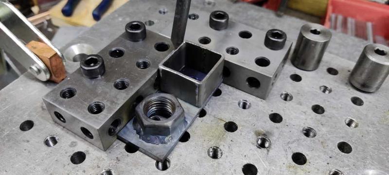
barclamps_jig_for_tacking_end_caps_800.jpg


I started with the end caps. As the holes in the bits of flat bar were drilled oversize (14 mm), the alignment of these isn't especially critical, but I used my fixture plate again just because it made it easy and quick. With the box section piece and the plate against the two 20–40–80 blocks, I tacked the corner nearest, then pulled it out of the jig and tacked the opposite corner.

barclamps_end_cap_tacked_800.jpg


I tacked all of the end caps in one go rather than tacking one, welding it and then tacking the next.

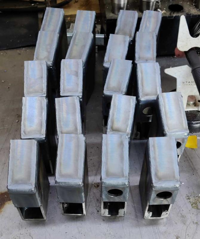
barclamps_end_caps_all_welded_800.jpg


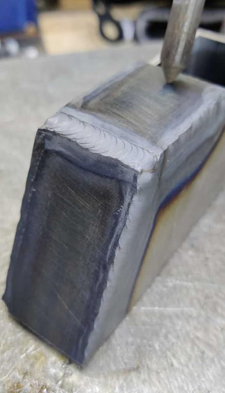
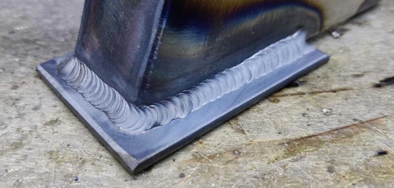
I then removed the jig from the bench and welded all the caps on autogenously (without filler rod). These parts are mainly aesthetic, so the welds don't have to be very robust.

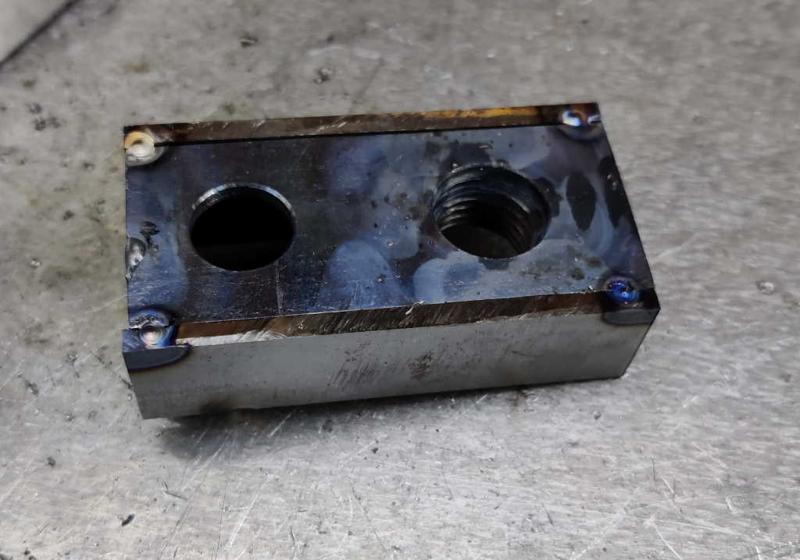
barclamps_end_caps_after_grinding_800.jpg


After welding, I cleaned the corners up with the angle grinder. Hopefully these parts will look a bit better after painting.

There are now 50 pieces left to weld together to make the 10 end plates, plus the 10 split nuts to complete the screw jaws.
 
My goodness, this is something of a marathon effort.
 
Andyp":135c1egb said:
I’ve lost track. How many are you making?

The plan is for 8 clamp mechanisms and 12 bars. The mechanisms (each consisting of a pair of jaws & an end plate) can be moved between bars depending on what length I want to use.

For the clamp mechanisms, I had enough material to make 10, so I figured I might as well as there's every chance I'll make a mistake or want to experiment with something. Hopefully even if that happens I'll still get 8 clamp mechanisms out of it.
 
I guess then that the journey must be just as enjoyable as the destination.
I admire your dedication and patience. That level of repetition would drive be up the wall.
 
Andyp":188q5elx said:
I guess then that the journey must be just as enjoyable as the destination.
I admire your dedication and patience. That level of repetition would drive be up the wall.

I completely understand that sentiment. It's probably worth saying though that the repetition isn't as bad as it looks (bearing in mind I find TIG welding quite relaxing). For example, to weld all 20 jaws onto the frames took me just under an hour & that was probably one of the longest jobs in terms of doing the same thing over-and-over. Even that could have been sped up if I had just done a few short welds (which would have been ample) rather than going all the way round (which I think looks better). Compare that length of time to how long it would take to hand cut all the dovetails on a chest of drawers and it doesn't seem that repetitive to me.
 
Dr.Al":1kyhe8jw said:
Andyp":1kyhe8jw said:
I guess then that the journey must be just as enjoyable as the destination.
I admire your dedication and patience. That level of repetition would drive be up the wall.

I completely understand that sentiment. It's probably worth saying though that the repetition isn't as bad as it looks (bearing in mind I find TIG welding quite relaxing). For example, to weld all 20 jaws onto the frames took me just under an hour & that was probably one of the longest jobs in terms of doing the same thing over-and-over. Even that could have been sped up if I had just done a few short welds (which would have been ample) rather than going all the way round (which I think looks better). Compare that length of time to how long it would take to hand cut all the dovetails on a chest of drawers and it doesn't seem that repetitive to me.

Thats a fair point too and probably why I know enjoy turning so much. From log to finished project in just a couple of hours. Mind you trying to turn 2 of anything and getting them to look identical a real challenge.
 
barclamps_end_plate_parts_800.jpg


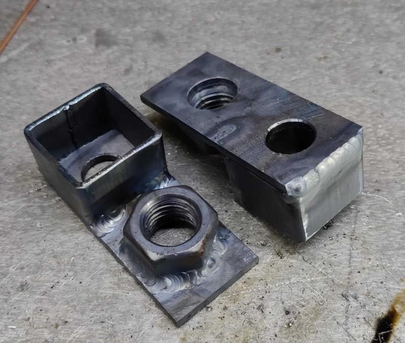
The end plates were next. The holes drilled in the end plate are 16 mm and 14 mm. The smaller hole is the equivalent of the hole in the end cap - a very loose fit for the M12 set screw that holds the end plate in place. The 16 mm hole is a close-ish fit on the the M16 threaded rod for the clamping screw. Ideally this would have been drilled a bit bigger to make sure that the threaded rod easily cleared the hole (as I did on the back plates for the screw jaws), but having a 16 mm hole means that I can use the hole to help align the nut in the right place. If the nut moves slightly during welding and the hole is causing interference with the threaded rod, I can pass a tap through from the nut side and extend the thread into the plate.

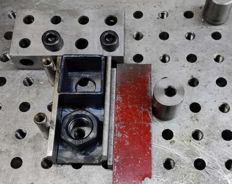
barclamps_end_plates_nut_jig_800.jpg


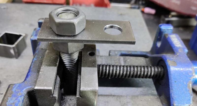
This shows the "jig" I used to position the nuts. It's a bit of threaded rod held in a vice with a nut above and below the plate. The nut above the plate can easily be lined up with the plate for a consistent orientation.

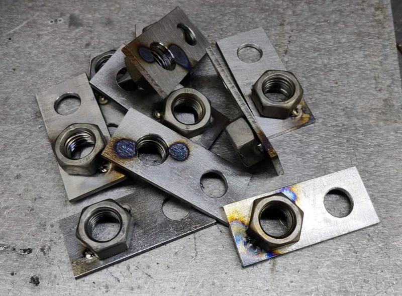
barclamps_end_plates_nuts_tacked_800.jpg


I tacked two sides of each nut while it was in the jig, then removed it from the jig.

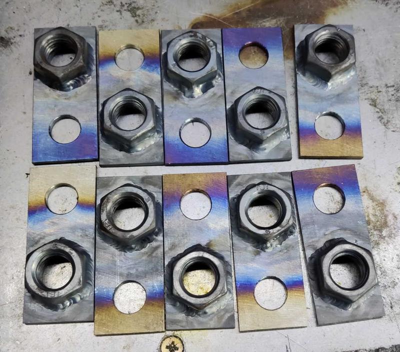
barclamps_end_plates_nuts_welded_on_800.jpg


I then welded round all six sides of each nut. This is probably overkill (two sides would have provided plenty of strength), but I was enjoying welding.

barclamps_end_plates_box_section_jig_800.jpg


The small piece of 30 mm × 30 mm × 2 mm box section is there to help align the end plate with the long bars while the M12 screw is tightened to hold them in place. It's not really necessary and I partly only added it as it adds some symmetry with respect to the end caps on the other end of the bars. To fit the box section, I used my fixture plate again; this made it very quick to add one tack in the corner.

barclamps_end_plates_box_section_tacked_800.jpg


I then took the piece out of the jig and tacked the other corner. As with most previous operations, I tacked all the parts together in one go and then went back to weld them all.

barclamps_end_plates_box_welded_on_800.jpg


As the box section isn't structural and to save me a lot of work grinding the sides down, I just welded the box section on two sides (and one of those sides was only partly welded due to access behind the nut).

barclamps_end_plate_side_jig_800.jpg


The side plates were attached using the fixture plate again. This time I swapped one of the 20–40–80 blocks for a couple of 8 mm dowel pins to give better access. The eccentric screw made clamping each one in place very quick.

barclamps_end_plate_sides_tacked_800.jpg


I tacked the two sides in place at the top while the end plates were in the jig.

barclamps_end_plate_tacked_on_rear_800.jpg


I then tacked the rear in a few places to hold it firmly.

barclamps_all_end_plates_welded_800.jpg


Finally, I welded round three sides of each side plate. I'll probably round all the edges and corners off with an angle grinder once the weather improves (I prefer to do angle grinding outside), but otherwise these parts are complete and ready for painting.

The only remaining welding to do on this project (unless I've forgotten something!) is to attach the second M16 split nut to its threaded rod to hold the threaded rod in place on the screw jaw.
 
barclamps_model_screw_jaw_with_thrust_bearing_800.jpg


Following a suggestion from @9fingers, I decided to try using a thrust bearing on the screw jaw to make the action of the screw a bit smoother as it's tightened. This has the (potential) disadvantage that it could reduce the ability to cope with angular misalignment, but hopefully the reinforcement of the end plate with side pieces and the relatively accurate drilling of holes with the milling machine should stop that being an issue. The bearings I'm using are designated as 51103: 17 mm inner diameter, 30 mm outer diameter and 9 mm thick; I bought 10 of them for £15, although I could have cut that in half if I were patient enough to wait for delivery from the far east.

The other problem this introduces is how to paint the parts. My plan had been to get everything welded together and then paint. It's going to be quite hard to paint the plate on the jaw and the split nut on the thread without getting paint on the thrust bearing. I'm aiming for at least eight clamp bodies, but have been making ten of each part to give myself some scope for messing things up. Since that's the case, I thought I'd try painting one of the jaws before doing the final weld. All being well, the final weld will be far enough away from the paint that the heat won't ruin the paint! I'll have to paint the outer split nut after welding it to the threaded rod, but this is a small enough area that it should be easy-ish to do with a brush (or I could leave that part unpainted).

barclamps_screwjaw_masked_800.jpg


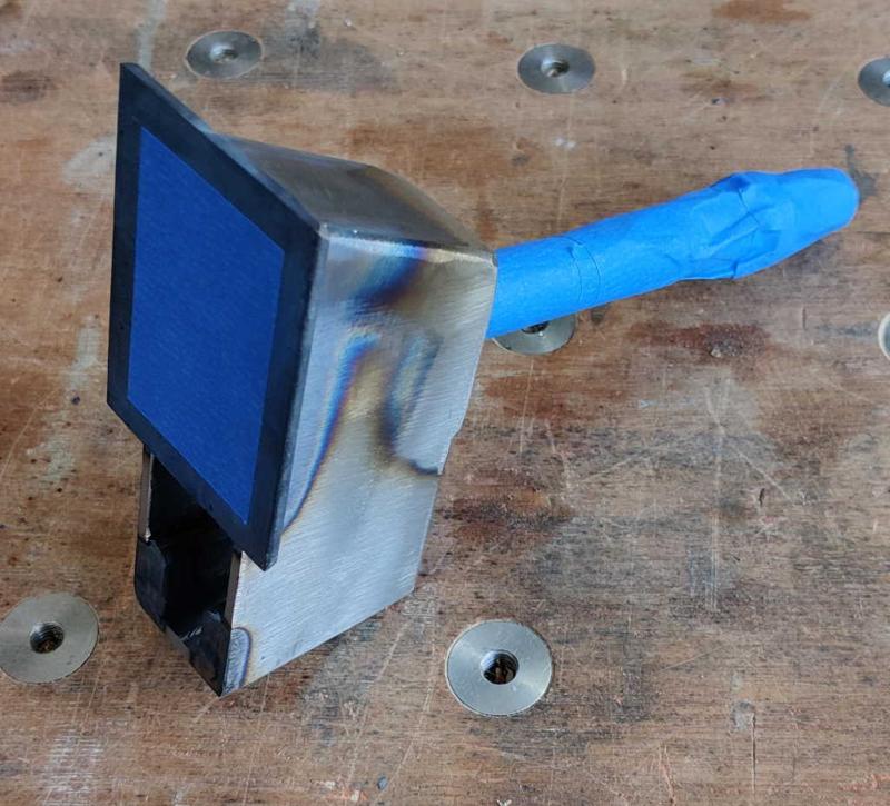
There are going to be wooden pads attached to the jaws (to stop the jaws from damaging the workpiece being clamped). These will be glued in place (Neil Paskin used hot melt glue and I will probably try the same). To be sure that the glue has something (other than paint) to adhere to, I masked the central area of the jaws with masking tape. I also masked the threaded rod to stop paint from getting into the threads. For this one, I haven't masked the area where the box section goes (although for the sliding jaw, I hung it on a bit of threaded rod to stop paint getting into the half-nut); it would be much easier not to have to mask the internal area, so I thought I'd try not doing so and see whether it's okay.

barclamps_setup_for_painting_one_pair_800.jpg


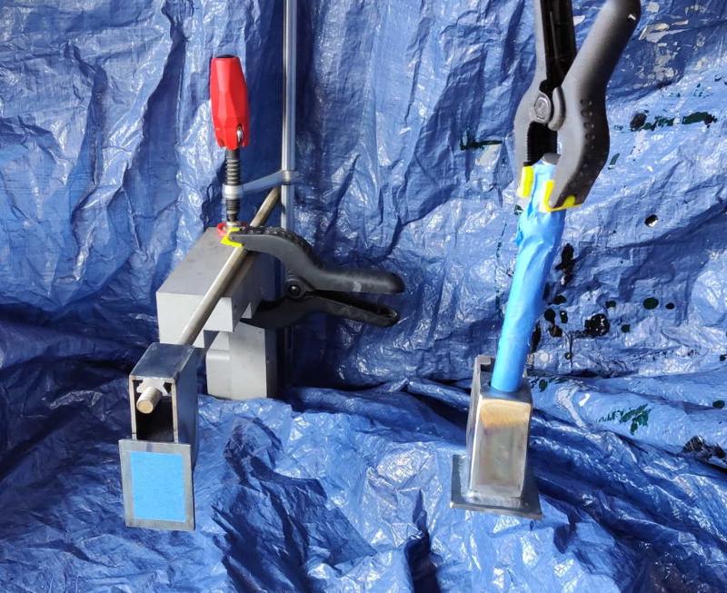
This photo shows the set-up I used for painting a pair of jaws (I also covered the rear clamp with a rag to stop the clamp from getting painted). The screw jaw is simply hanging from a spring clamp, which is attached to the ceiling with a bit of wire. The strange-shaped bit of aluminium that is clamped down (to my temporary shelf, which has been covered in a tarpaulin) is something that came out of a skip a while ago and just seemed a good shape.

barclamps_one_pair_primer_coat_800.jpg


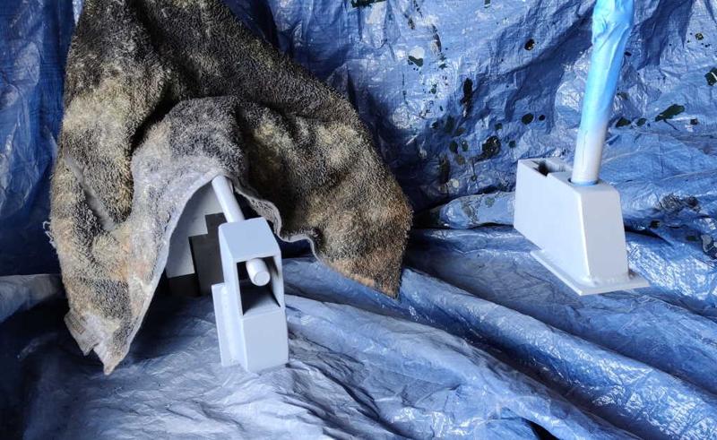
I gave both jaws a coat of primer (Tractol Light Grey) and left them over night. This was my first go at using spray paint and I was pleased with how easy it was (compared to brushing) to get a good even coat.

barclamps_two_jaws_painted_800.jpg


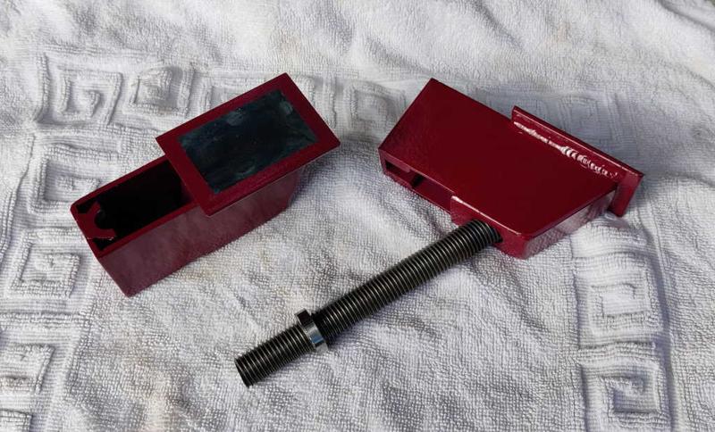
I then gave them two coats (about 10 hours apart) of Tractol RAL 4004 ("Claret Red"), again sprayed onto the jaws. Once the second coat had been left overnight to dry, I peeled the masking tape off.

The next job is to fit the thrust bearing and weld the split nut into place. It'll be interesting to see what the paint looks like after I've done that!
 
I'd thread all the bearing in a stack on a scrap piece of bar/ threaded rod and wrap in tape.
with a knife slice off each wrapped bearing in turn and then complete the painting.
This should give adequate masking but not to excess allowing the rest of the metal to be painted.

Bob
 
Back
Top