Phil
Old Oak
Beehive Construction
Part 1 of another exciting wood project, something very different this time, and no rocket science (says he full of confidence).
A very old friend of mine lives on a farm close by and has a couple of hives.
We visited recently and he asked if I could make a hive. He will let me have an old hive as a sample.
A requirement of the new hive was to have a slightly longer landing strip, not for heavily laden bees to land but for a holding cage. Will deal with that one later on.
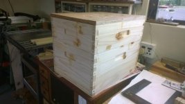
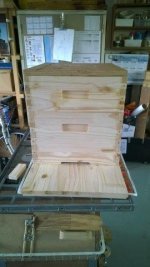
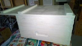
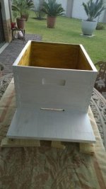
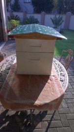
The sample box arrived one Friday and went onto the patio, certainly no place in the garage!
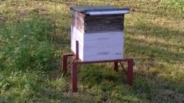
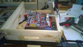
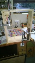
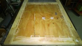
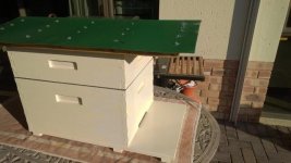
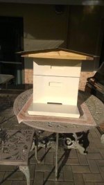
Sample Box -
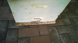
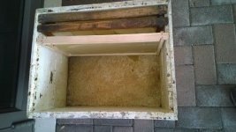
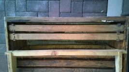
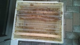
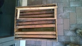
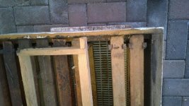
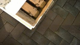
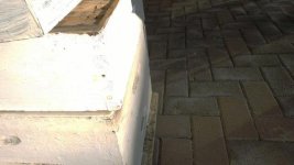
First up was measuring the internal dimensions of the brood box (queen bee breeding) and super (honey) box as these are important for hanging the frames. The outside measurements would be adjusted accordingly.
Before putting pencil to paper I did some WWW searching. This is a 10 frame Langstroth hive.
The Reverend Lorenzo Langstroth patented the design in in 1852.
Some reading:
https://en.wikipedia.org/wiki/Langstroth_hive
https://en.wikipedia.org/wiki/L._L._Langstroth
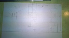
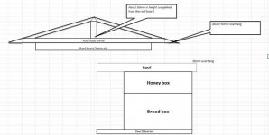
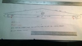
It was then down to measuring existing boxes and drawing to scale to get a feeling and plan of action.
Also to plan the works order process to eliminate cock-ups – aka F-Up-F.
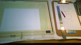
As this is a “test” run I decided to use good ‘ol SA Pine with all its defects.
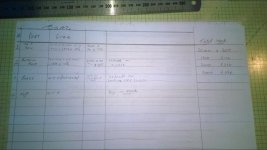
The M-Cad-BOM calculated I need 2 lengths of 20 x 305 x 3000mm. With very careful nesting and cutting I should be ok (famous last words! The F-Up-Fairy paid a visit or two ……… )
20mm thick? Will deal with this later on.
The width of the boards required were 150mm for top and 255mm bottom. The 305mm width is a good choice.
Visited first Mica (4.5km from home) stock not what I want. Next onto Chamberlains (5.5km from home).
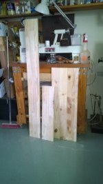
Ok, a large number of boards on the shelf.
Start unpacking the shelf looking for straightest, no warp, as few knots as possible, no wavey bends, clean boards.
Fortunately, Chamberlains employs young chaps to do this work, I struggle a bit with the long boards.
Once I had paid he even loaded it onto the back of the LDV. (Declined a tip).
Back home, the wife was away visiting kids for 2 days, more space in the garage. Machines were moved so that I could rip cut, crosscut, and use the router table.
So, I could now offload and did the first cuts on the RAS.
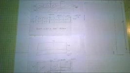
Measure and cut trying to avoid having the knots on a joint.
The first board (#1) was cut at 1040mm long. This is the 4 top panels.
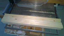
Then to the table saw to do the ripping into 150mm widths. These boards went back to the RAS for cutting – 2 x 510mm and 2 x 415mm
Top box cut, mark with chalk and place carefully in a safe place ready for further machining.
Board #1 left over was than trimmed on the table saw to a width of 255mm.
Then back to the RAS to cut 2 x 510mm and 2 x 415mm
Bottom box cut, mark with chalk and place carefully in a safe place ready for further machining.
Board #2 would provide the base and top.
The base being 415mm wide and 700mm long required 2 boards to be joined.
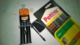
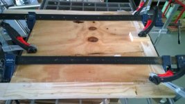
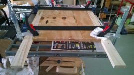
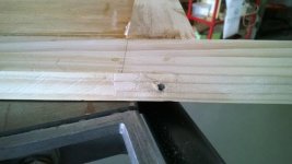
Lots of glue and a couple of #20 biscuits. Clamped down, there was a slight ridge where the 2 boards are joined (not sure of cause, but will look at it when out of clamps)
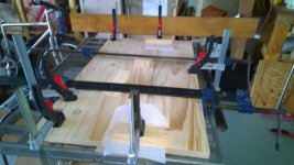
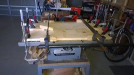
While this was curing, time to plan the handholds for the boxes.
Handholds
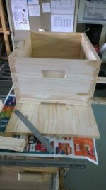
Each box and side gets a handhold for picking them up.
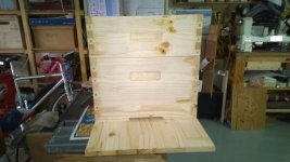
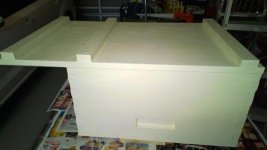
This is what the sample box looks like
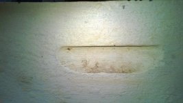
The easiest way is on the router table using a straight fluting bit.
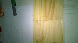
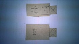
As this is a blind-upside-down rout, a paper template is drawn for the narrow and wider boards.
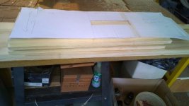
The router table is prepared, the bit raised to the right height, the fence set back from the bit.
The template is then used to clamp down some scraps on the sides and front.
Ear protection on, vacuum switches on with the router, first board placed down.
Move board around side ways and back to front. Lift off – looks good.
Same process for all the other boards, just moving the scraps for the longer boards.
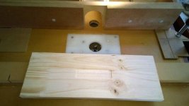
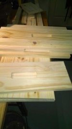
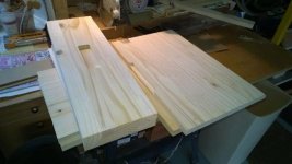
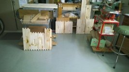
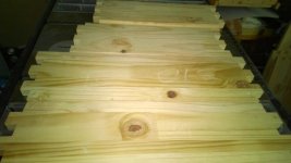
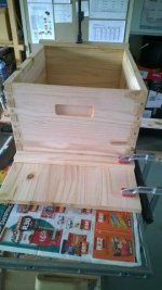
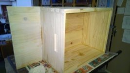
Hand holds cut and front entrance routed
Right, a design error. The bottom side of the hand hold needs to be sloped down so as not to accumulate water.
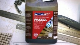
I only realised this after assembly and it was too late to do anything about it. The boxes had already been undercoated for painting.
Rebate for frames
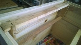
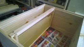
The width side of the box has a rebate at the top where the frames are placed.
The measurement is taken from the sample box (this will come back and bite later on)
Easy job.
Set the fluting bit in the router. Mark a board.
Push the 4 boards over, adjust the height until rebate correct size.
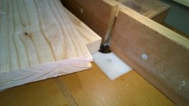
Adjusting the height is a bit of a schlep – The table top lifts up and has a stay to keep it there and a slide over the join. (the slide was fitted afterwards - after I was in a hurry one day, bumped the stay, just could not get my hand out fast enough. The middle finger was caught and fractured. The table top weight is very heavy, the top is 20mm MDF, the large Ryobi router and then the heavy fence) There was lots of blue air.
Had to wear a splint, it leant a whole new meaning to flipping the bird :lol: :lol:
Thank you for reading
Phil
Part 1 of another exciting wood project, something very different this time, and no rocket science (says he full of confidence).
A very old friend of mine lives on a farm close by and has a couple of hives.
We visited recently and he asked if I could make a hive. He will let me have an old hive as a sample.
A requirement of the new hive was to have a slightly longer landing strip, not for heavily laden bees to land but for a holding cage. Will deal with that one later on.
The sample box arrived one Friday and went onto the patio, certainly no place in the garage!
Sample Box -
First up was measuring the internal dimensions of the brood box (queen bee breeding) and super (honey) box as these are important for hanging the frames. The outside measurements would be adjusted accordingly.
Before putting pencil to paper I did some WWW searching. This is a 10 frame Langstroth hive.
The Reverend Lorenzo Langstroth patented the design in in 1852.
Some reading:
https://en.wikipedia.org/wiki/Langstroth_hive
https://en.wikipedia.org/wiki/L._L._Langstroth
It was then down to measuring existing boxes and drawing to scale to get a feeling and plan of action.
Also to plan the works order process to eliminate cock-ups – aka F-Up-F.
As this is a “test” run I decided to use good ‘ol SA Pine with all its defects.
The M-Cad-BOM calculated I need 2 lengths of 20 x 305 x 3000mm. With very careful nesting and cutting I should be ok (famous last words! The F-Up-Fairy paid a visit or two ……… )
20mm thick? Will deal with this later on.
The width of the boards required were 150mm for top and 255mm bottom. The 305mm width is a good choice.
Visited first Mica (4.5km from home) stock not what I want. Next onto Chamberlains (5.5km from home).
Ok, a large number of boards on the shelf.
Start unpacking the shelf looking for straightest, no warp, as few knots as possible, no wavey bends, clean boards.
Fortunately, Chamberlains employs young chaps to do this work, I struggle a bit with the long boards.
Once I had paid he even loaded it onto the back of the LDV. (Declined a tip).
Back home, the wife was away visiting kids for 2 days, more space in the garage. Machines were moved so that I could rip cut, crosscut, and use the router table.
So, I could now offload and did the first cuts on the RAS.
Measure and cut trying to avoid having the knots on a joint.
The first board (#1) was cut at 1040mm long. This is the 4 top panels.
Then to the table saw to do the ripping into 150mm widths. These boards went back to the RAS for cutting – 2 x 510mm and 2 x 415mm
Top box cut, mark with chalk and place carefully in a safe place ready for further machining.
Board #1 left over was than trimmed on the table saw to a width of 255mm.
Then back to the RAS to cut 2 x 510mm and 2 x 415mm
Bottom box cut, mark with chalk and place carefully in a safe place ready for further machining.
Board #2 would provide the base and top.
The base being 415mm wide and 700mm long required 2 boards to be joined.
Lots of glue and a couple of #20 biscuits. Clamped down, there was a slight ridge where the 2 boards are joined (not sure of cause, but will look at it when out of clamps)
While this was curing, time to plan the handholds for the boxes.
Handholds
Each box and side gets a handhold for picking them up.
This is what the sample box looks like
The easiest way is on the router table using a straight fluting bit.
As this is a blind-upside-down rout, a paper template is drawn for the narrow and wider boards.
The router table is prepared, the bit raised to the right height, the fence set back from the bit.
The template is then used to clamp down some scraps on the sides and front.
Ear protection on, vacuum switches on with the router, first board placed down.
Move board around side ways and back to front. Lift off – looks good.
Same process for all the other boards, just moving the scraps for the longer boards.
Hand holds cut and front entrance routed
Right, a design error. The bottom side of the hand hold needs to be sloped down so as not to accumulate water.
I only realised this after assembly and it was too late to do anything about it. The boxes had already been undercoated for painting.
Rebate for frames
The width side of the box has a rebate at the top where the frames are placed.
The measurement is taken from the sample box (this will come back and bite later on)
Easy job.
Set the fluting bit in the router. Mark a board.
Push the 4 boards over, adjust the height until rebate correct size.
Adjusting the height is a bit of a schlep – The table top lifts up and has a stay to keep it there and a slide over the join. (the slide was fitted afterwards - after I was in a hurry one day, bumped the stay, just could not get my hand out fast enough. The middle finger was caught and fractured. The table top weight is very heavy, the top is 20mm MDF, the large Ryobi router and then the heavy fence) There was lots of blue air.
Had to wear a splint, it leant a whole new meaning to flipping the bird :lol: :lol:
Thank you for reading
Phil