Dr.Al
Old Oak
Last weekend I was in Lyme Regis. No visit to that part of the world is complete without a trip to the second-hand tool store that forms part of Dolphin Antiques in Beer.
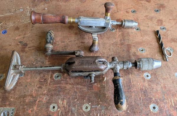
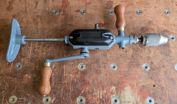
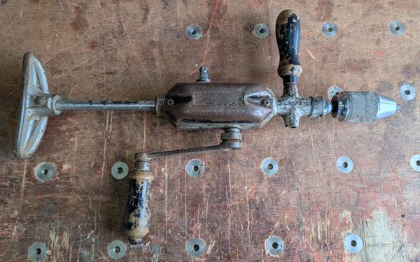
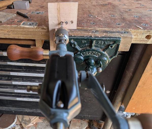
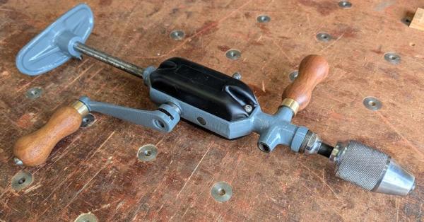
I was relatively restrained (by my standards). I came away with a slightly shabby breast drill and a few countersink bits for my hand brace. This is the breast drill, shown below a hand drill I bought a few years ago:
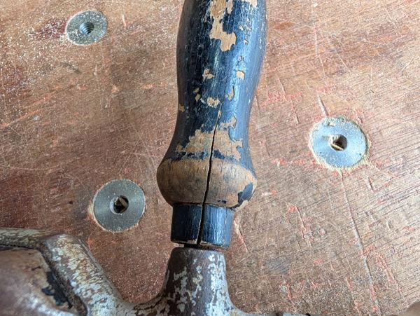
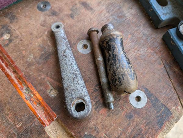
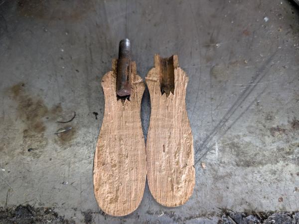
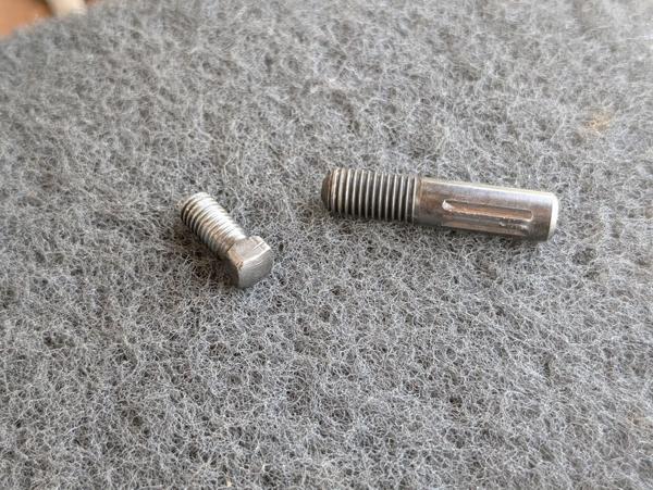
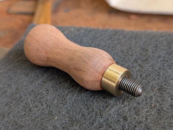
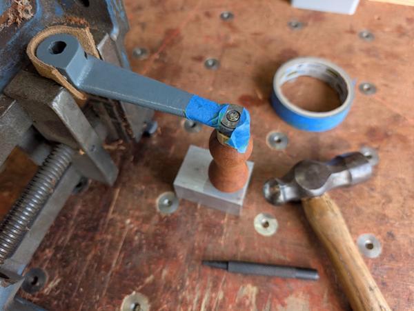
The drill is in need of a bit of a TLC. As it's going to be far too hot this weekend to start hand planing timber for my Bedside Table I thought I'd have a go at tidying up the drill instead. The handles are very shabby, especially the front one (which screws in on either side of front section). It has lost its ferrule and has a big crack in the side:
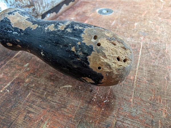
It's also suffering from woodworm of some sort:
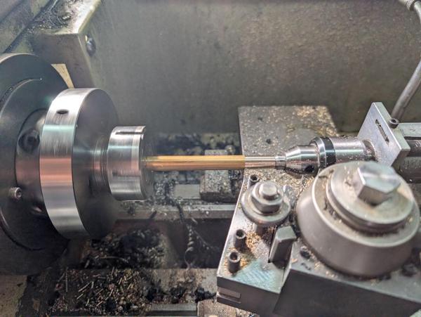
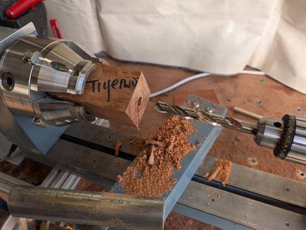
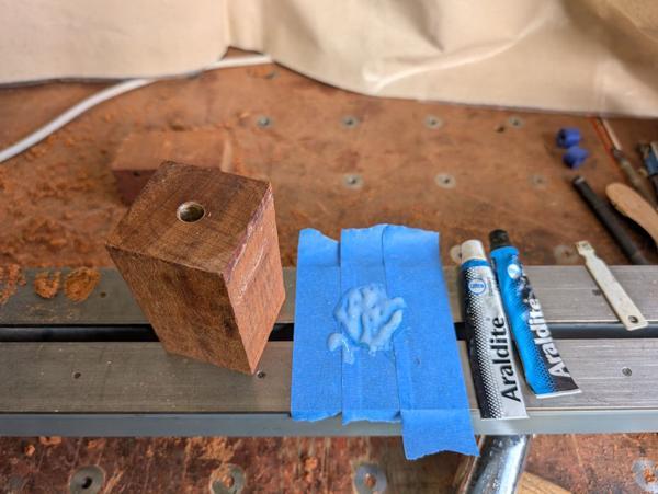
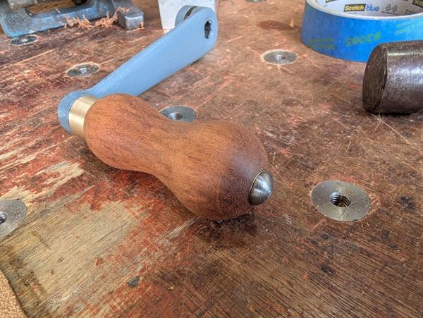
The rear handle isn't as bad, but it is also a bit shabby so I think I'll replace both of them.
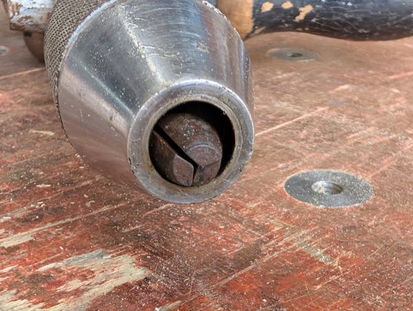
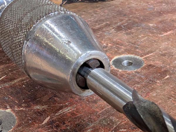
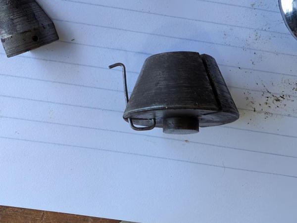
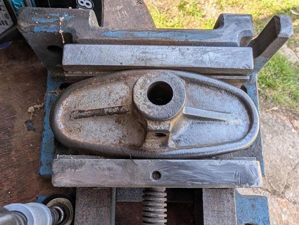
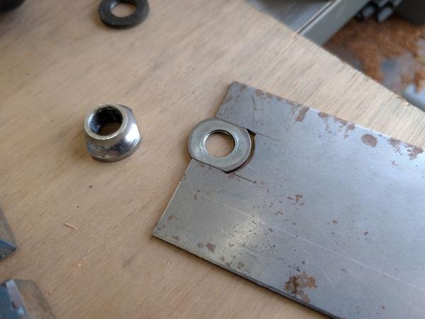
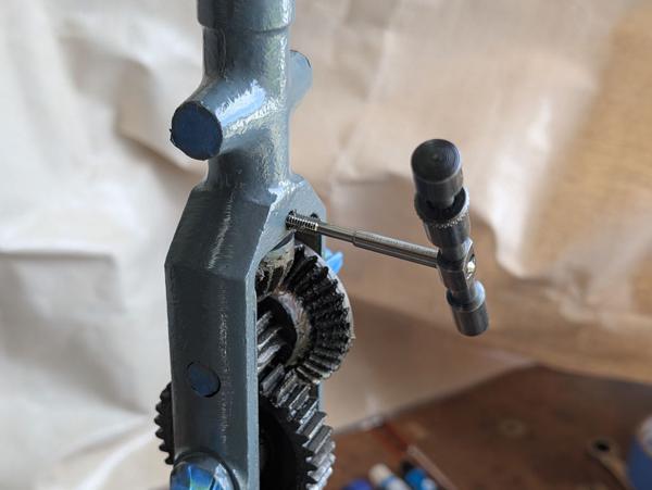
However, the first thing I wanted to deal with was the chuck. The chuck jaws don't open up in the manner I'd expect them to:
Despite that, it is possible to get a drill bit into the jaws and then they grip just fine:
I did a few quick tests and the drill works well in either speed setting (changed by swapping the rear handle to the other crank and then swapping the front handle so it doesn't get in the way):
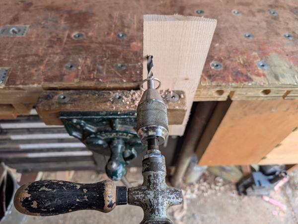
It's much nicer to use than the other sort of hand drill, which I've always found a bit too wobbly (due to the way you have to grip the rear handle) to get good results.
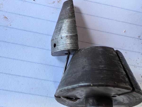
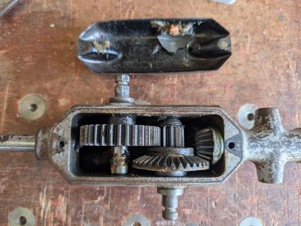
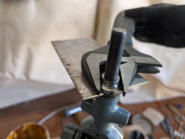
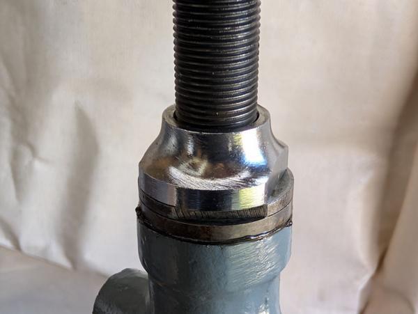
The first job with the chuck was to dismantle it. The rear part of the chuck body unscrews. I think this is intended to be done with a pin spanner, but it was loose enough that I could undo it simply by gripping the two parts and rotating:
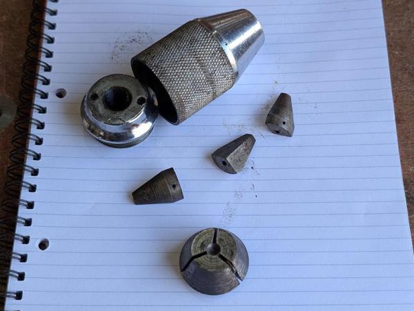
If you look closely at the component at the bottom of the photo, you'll see there's a spring in there (it wasn't attached to the jaw, just loose in the body). This is what the spring looked like when removed:
I was really pleased to find that as it gave me some important clues as to how the spring mechanism works. After trying it in quite a few different orientations, I eventually figured out that it goes into the base piece like this...
... and then the jaw fits over the hook on the end like this:
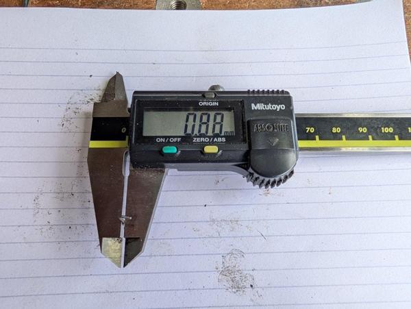
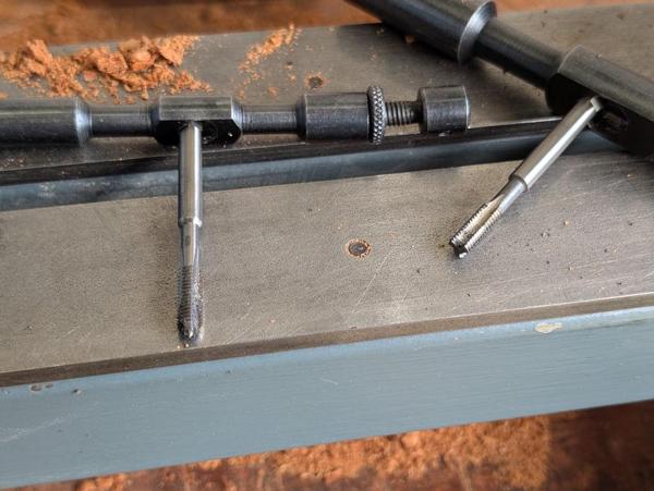
I measured the spring...
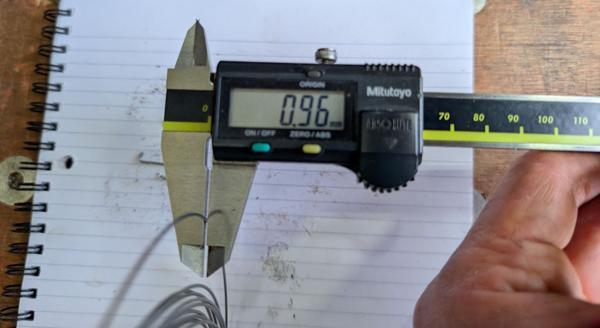
... and then dug out my collection of piano wire to find the closest size I had:
With pliers and side cutters, I could bend the piano wire into approximately the right shape:
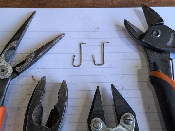
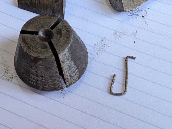
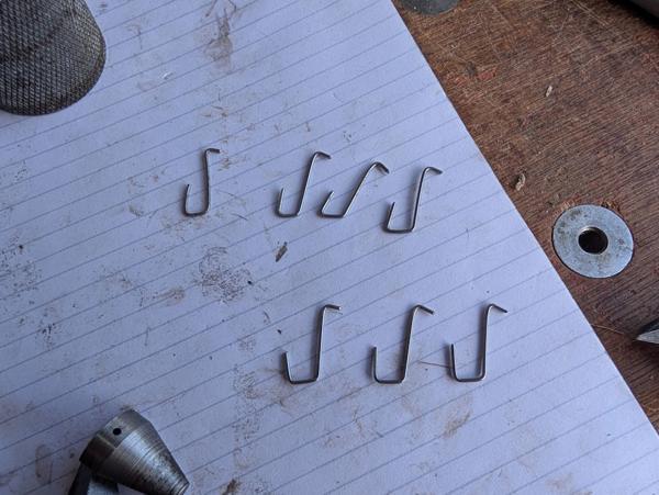
I ended up having quite a few goes at spring making, gradually refining the shape until I'd properly figured out how it was supposed to work:
The size of the spring is quite important, especially the length of the longest section. If that section is too short the jaw body doesn't clear the top of the lower part. If it is too long, the jaw will tend to lean in at the top, closing up the opening rather than springing apart as intended. The other dimensions are less important: the short tip needs to be long enough to go into the jaw but not so long that it pokes out the side; the bottom of the U shape needs to be about the same as the opening at the bottom of the base piece and the leg at the end can be pretty much any length without issue.
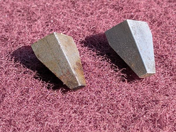
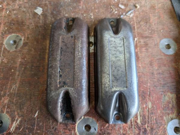
While the jaws were out, I gave them a clean up with some Scotchbrite. This gives a sort-of before-and-after view:
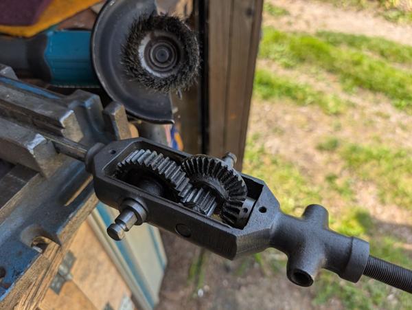
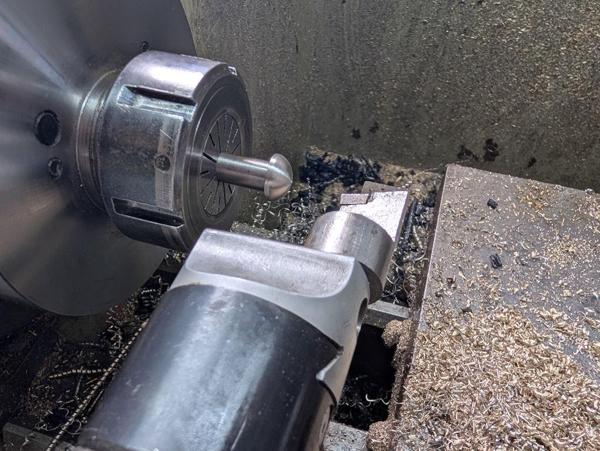
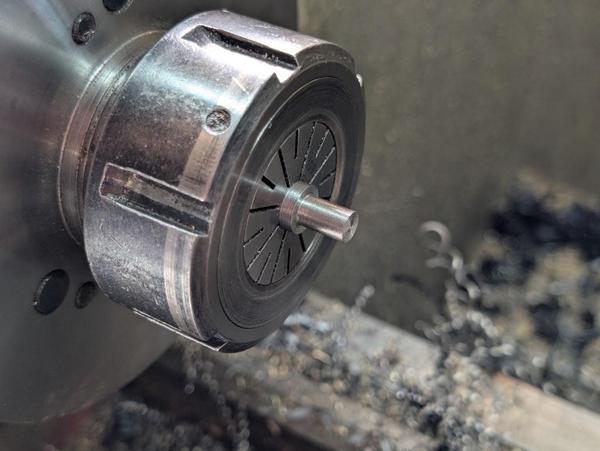
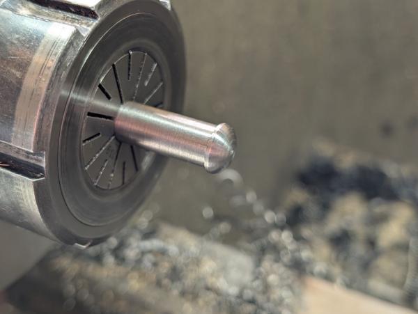
With the chuck reassembled (rather a lot of times as I tweaked the shape of the springs), the jaws now spring apart properly:
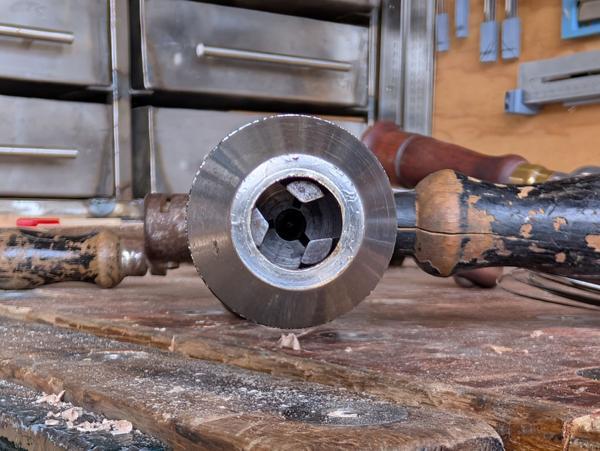
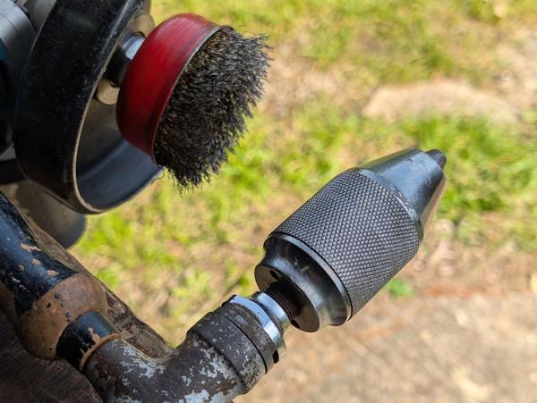
The last job on the chuck was to use a brass brush on a variable-speed angle grinder to clean up knurl, which had quite a bit of rusty pitting but now looks like this:
More to follow...
I was relatively restrained (by my standards). I came away with a slightly shabby breast drill and a few countersink bits for my hand brace. This is the breast drill, shown below a hand drill I bought a few years ago:
The drill is in need of a bit of a TLC. As it's going to be far too hot this weekend to start hand planing timber for my Bedside Table I thought I'd have a go at tidying up the drill instead. The handles are very shabby, especially the front one (which screws in on either side of front section). It has lost its ferrule and has a big crack in the side:
It's also suffering from woodworm of some sort:
The rear handle isn't as bad, but it is also a bit shabby so I think I'll replace both of them.
However, the first thing I wanted to deal with was the chuck. The chuck jaws don't open up in the manner I'd expect them to:
Despite that, it is possible to get a drill bit into the jaws and then they grip just fine:
I did a few quick tests and the drill works well in either speed setting (changed by swapping the rear handle to the other crank and then swapping the front handle so it doesn't get in the way):
It's much nicer to use than the other sort of hand drill, which I've always found a bit too wobbly (due to the way you have to grip the rear handle) to get good results.
The first job with the chuck was to dismantle it. The rear part of the chuck body unscrews. I think this is intended to be done with a pin spanner, but it was loose enough that I could undo it simply by gripping the two parts and rotating:
If you look closely at the component at the bottom of the photo, you'll see there's a spring in there (it wasn't attached to the jaw, just loose in the body). This is what the spring looked like when removed:
I was really pleased to find that as it gave me some important clues as to how the spring mechanism works. After trying it in quite a few different orientations, I eventually figured out that it goes into the base piece like this...
... and then the jaw fits over the hook on the end like this:
I measured the spring...
... and then dug out my collection of piano wire to find the closest size I had:
With pliers and side cutters, I could bend the piano wire into approximately the right shape:
I ended up having quite a few goes at spring making, gradually refining the shape until I'd properly figured out how it was supposed to work:
The size of the spring is quite important, especially the length of the longest section. If that section is too short the jaw body doesn't clear the top of the lower part. If it is too long, the jaw will tend to lean in at the top, closing up the opening rather than springing apart as intended. The other dimensions are less important: the short tip needs to be long enough to go into the jaw but not so long that it pokes out the side; the bottom of the U shape needs to be about the same as the opening at the bottom of the base piece and the leg at the end can be pretty much any length without issue.
While the jaws were out, I gave them a clean up with some Scotchbrite. This gives a sort-of before-and-after view:
With the chuck reassembled (rather a lot of times as I tweaked the shape of the springs), the jaws now spring apart properly:
The last job on the chuck was to use a brass brush on a variable-speed angle grinder to clean up knurl, which had quite a bit of rusty pitting but now looks like this:
More to follow...
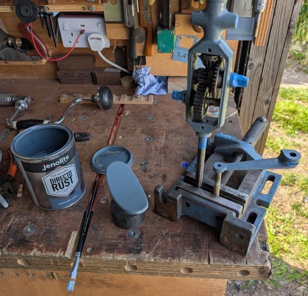
 . In need of some attention... bit of rust removal... repaint job... etc. Seem to recall buying it way back when I was 18+... 1979~80...


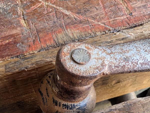
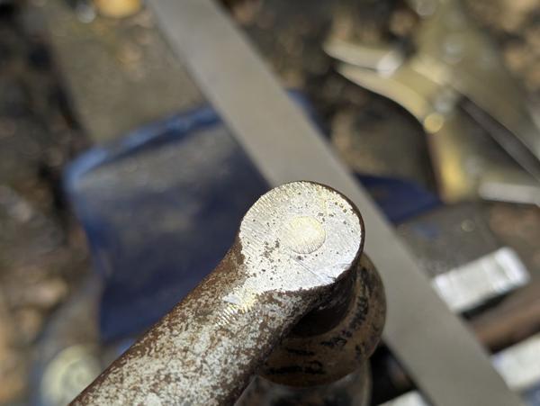
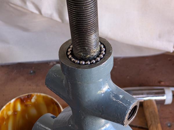
 ). Everything seems to be held into the body very firmly. Although I can't be sure, I think they've used lots of grub screws or the equivalent but peened over the ends to prevent them ever coming out again. For example:

 .
.


")
