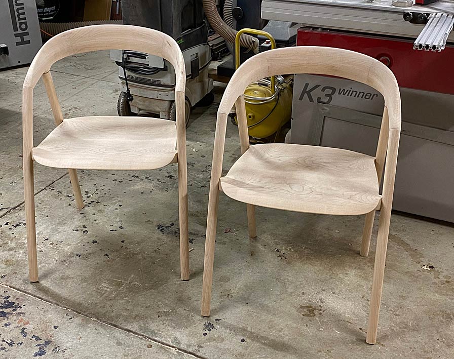
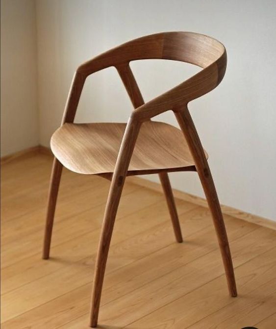
I have found that the shaping of the chair arms and back to be a complicated process, with a step forward, then sideways, and then another step forwards. It is not plain sailing. There are many small corrections to make as I proceed, and I dare not attempt to leave these until a later date. I thought that some here will find the corrections ... repairs ... interesting, and hopefully useful if you find yourself in the same situation.
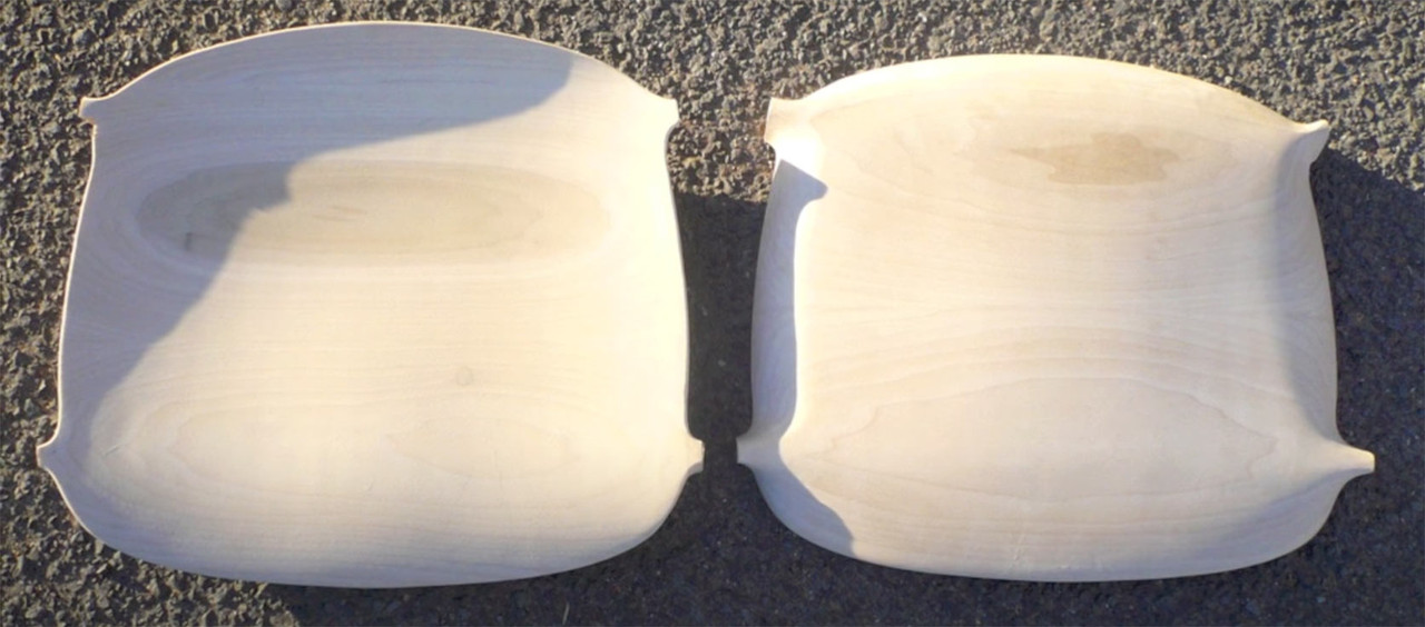
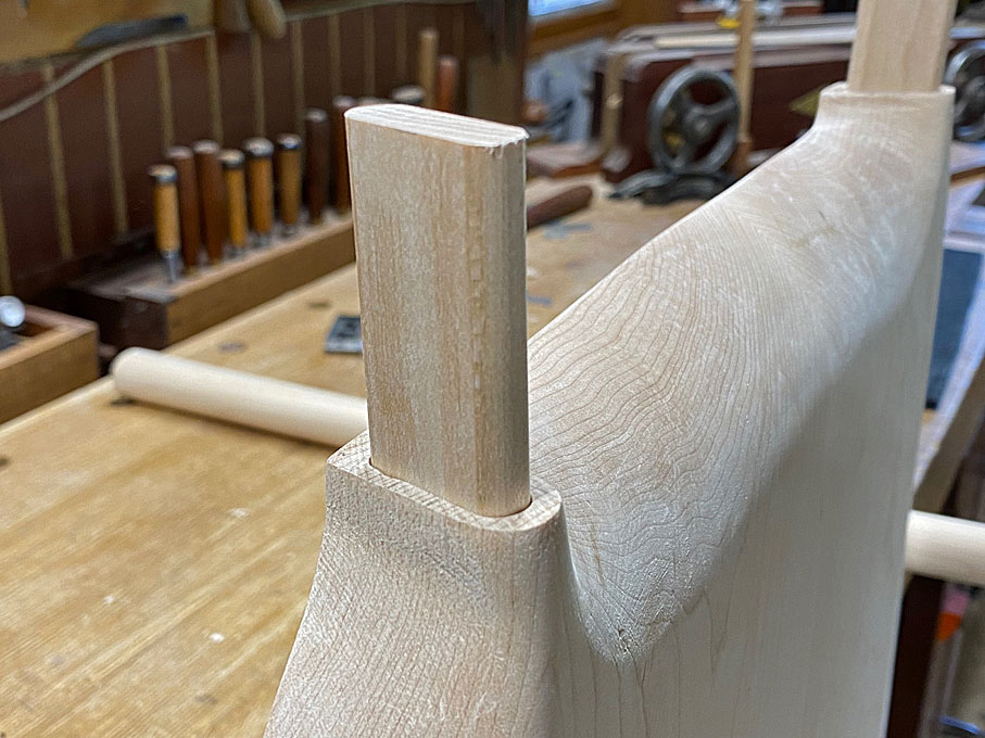
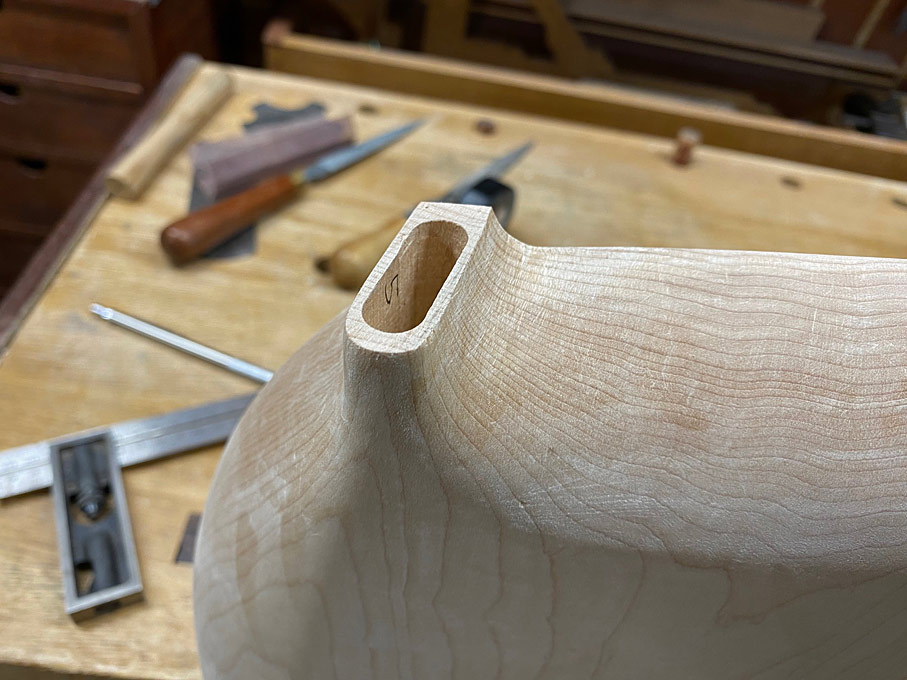
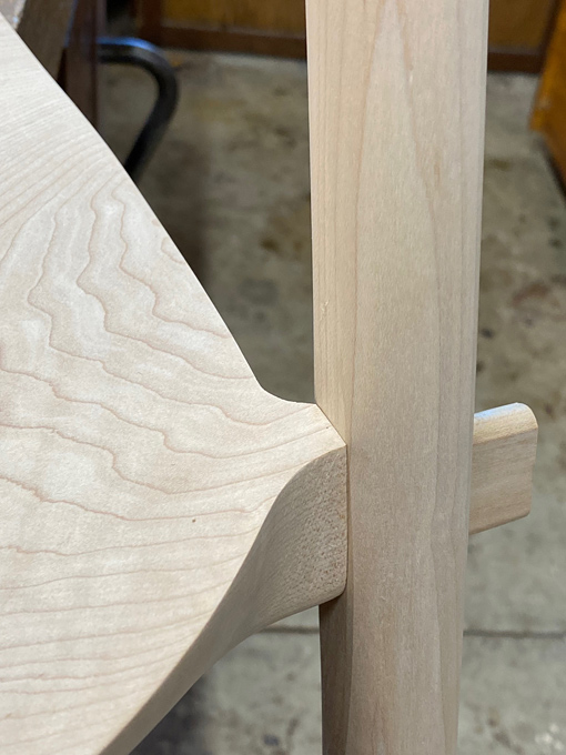
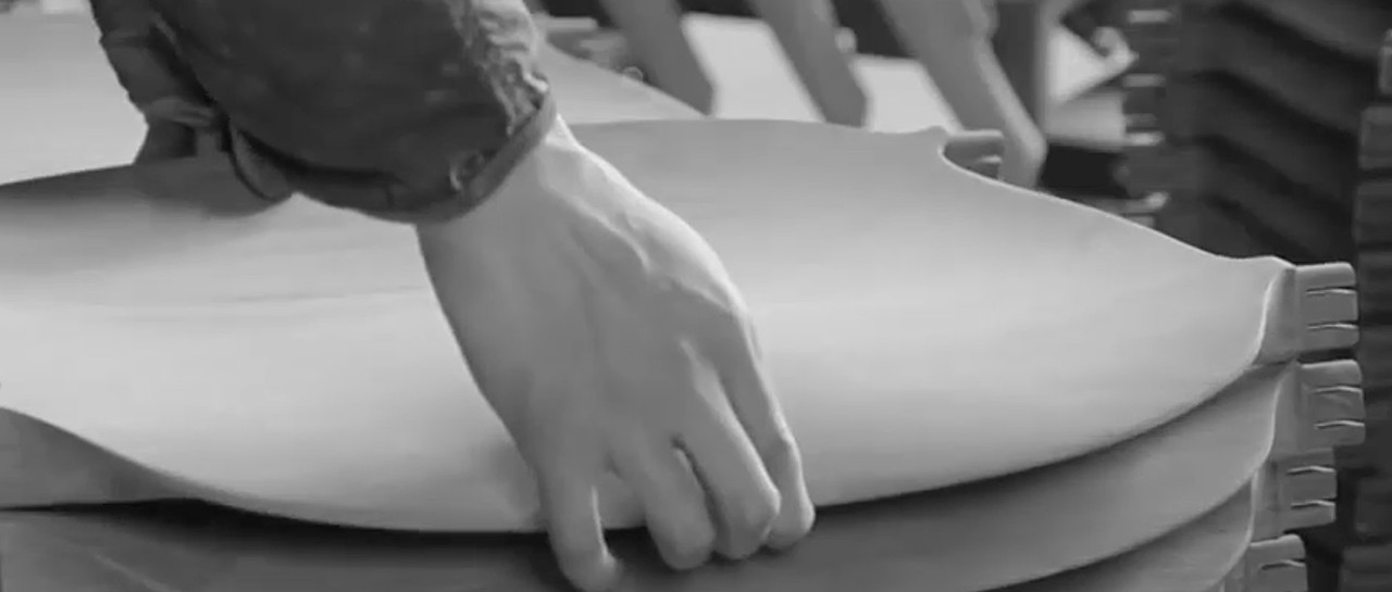
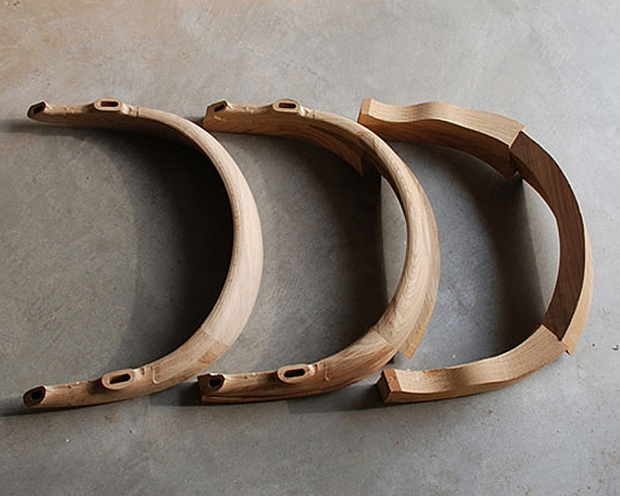
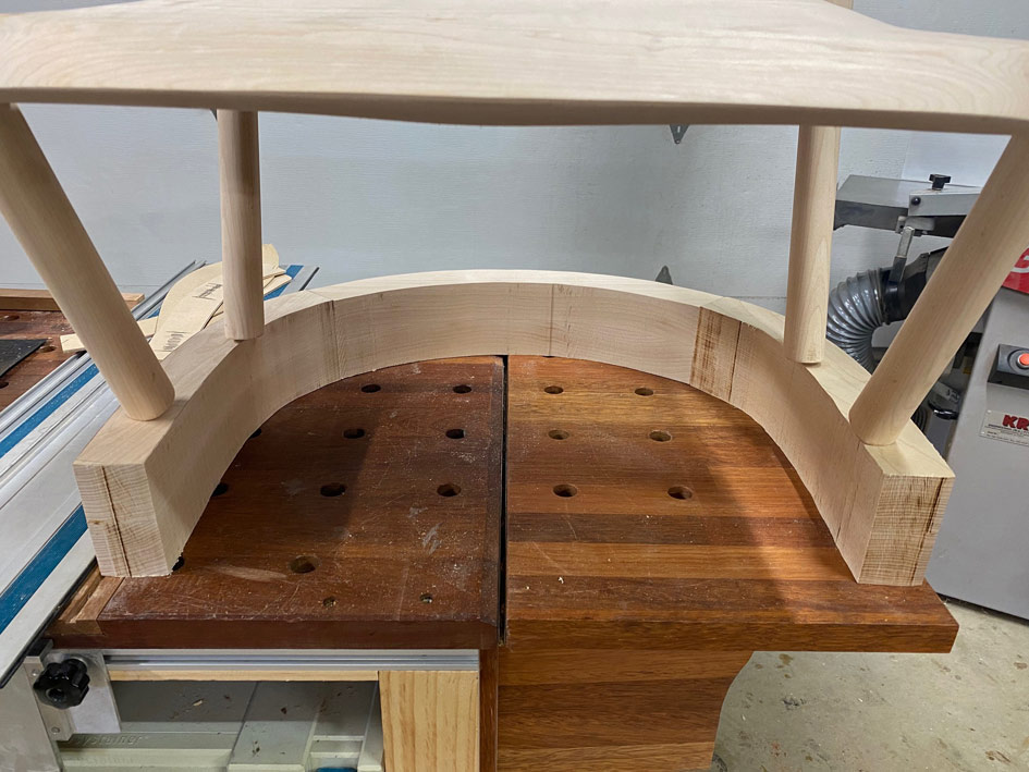
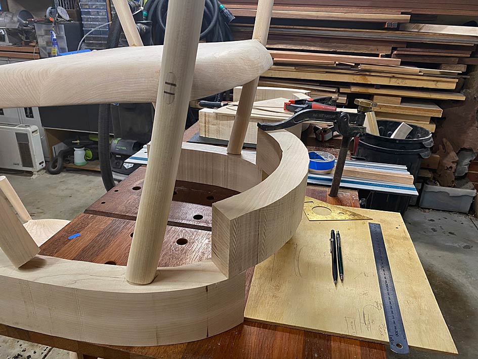
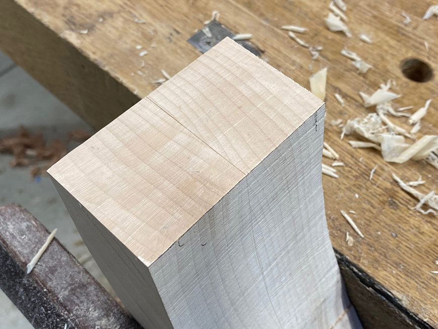
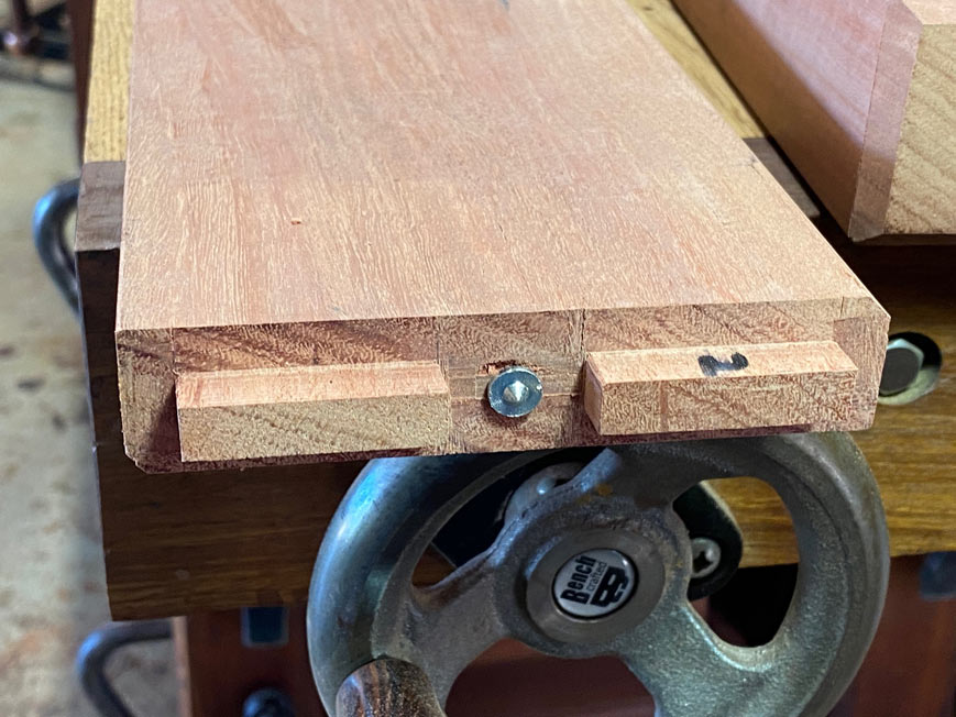
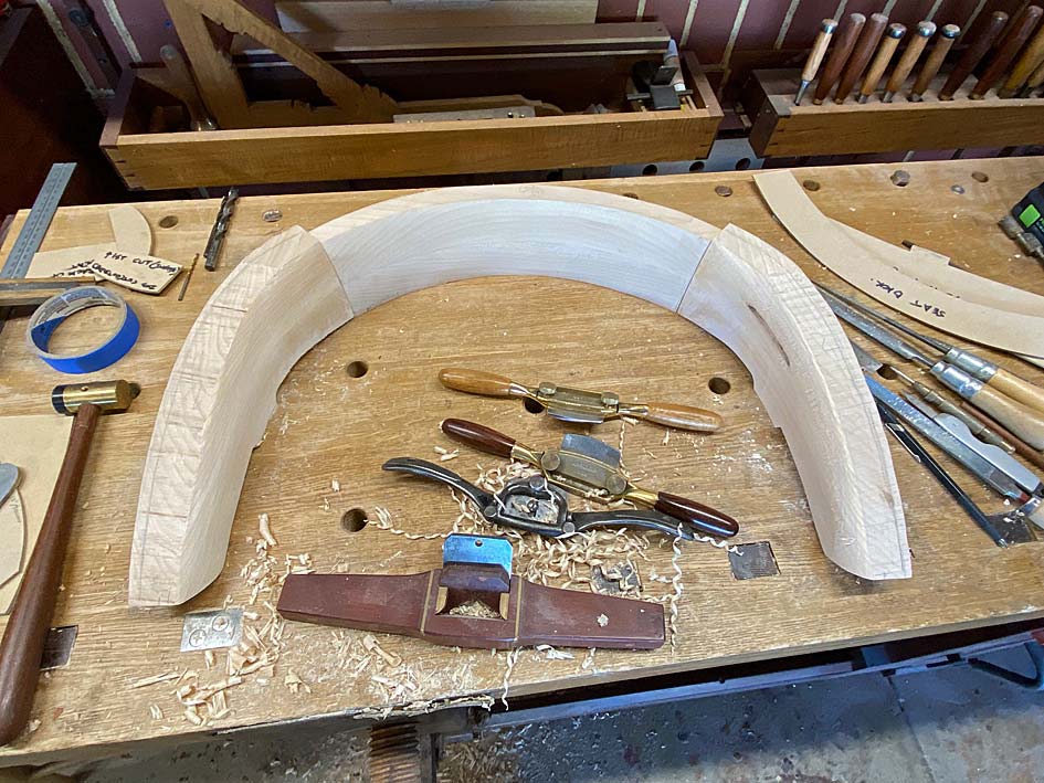
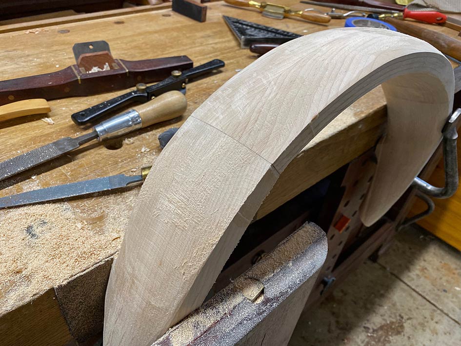
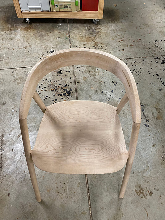
In the following photo, where the inside back is being shaped, you can see two joins where the arms and back connect ...

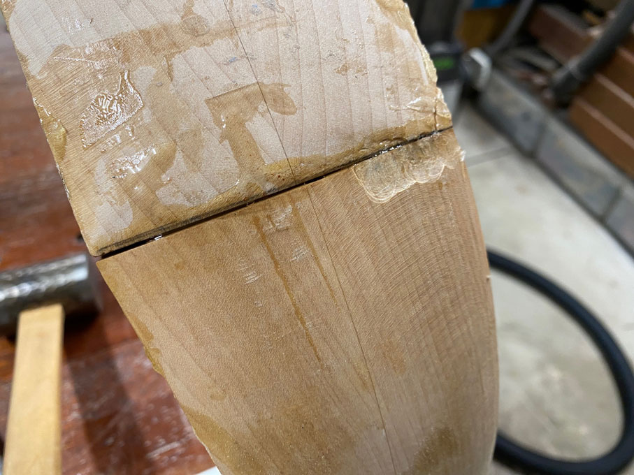
Outside example ..

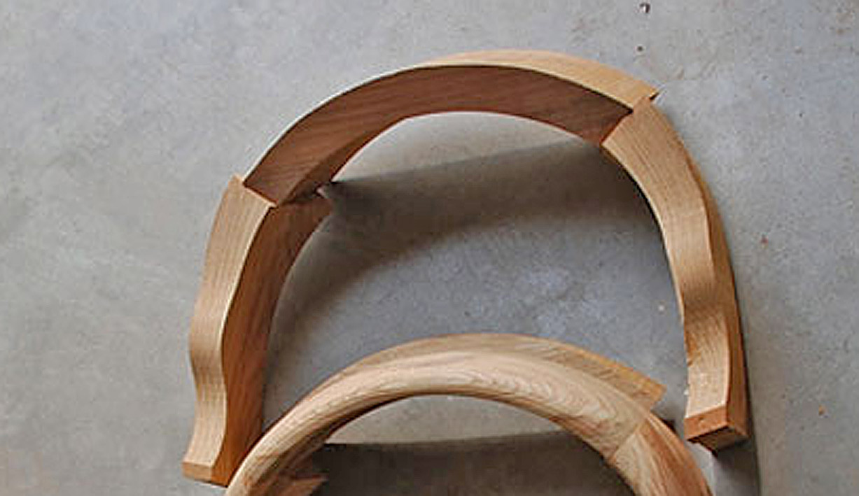
These joins are clean and tight. In all there were 8 such joins, 2 chairs with each 2 inside and 2 outside joins. Of these 8 joins, 7 were perfect. One was a disaster!
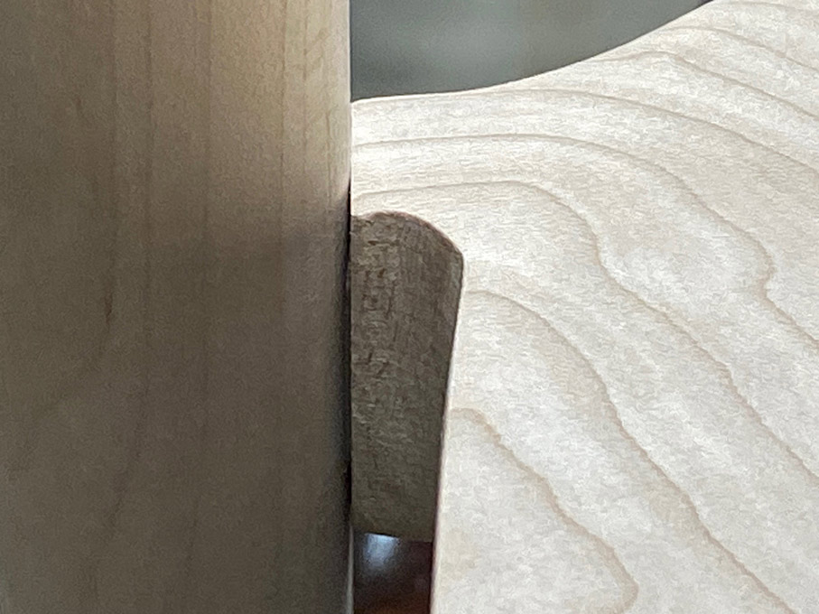
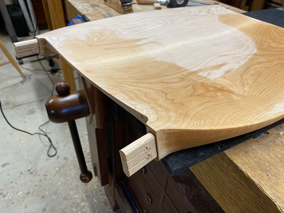
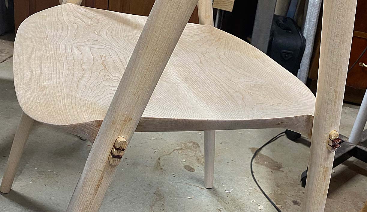
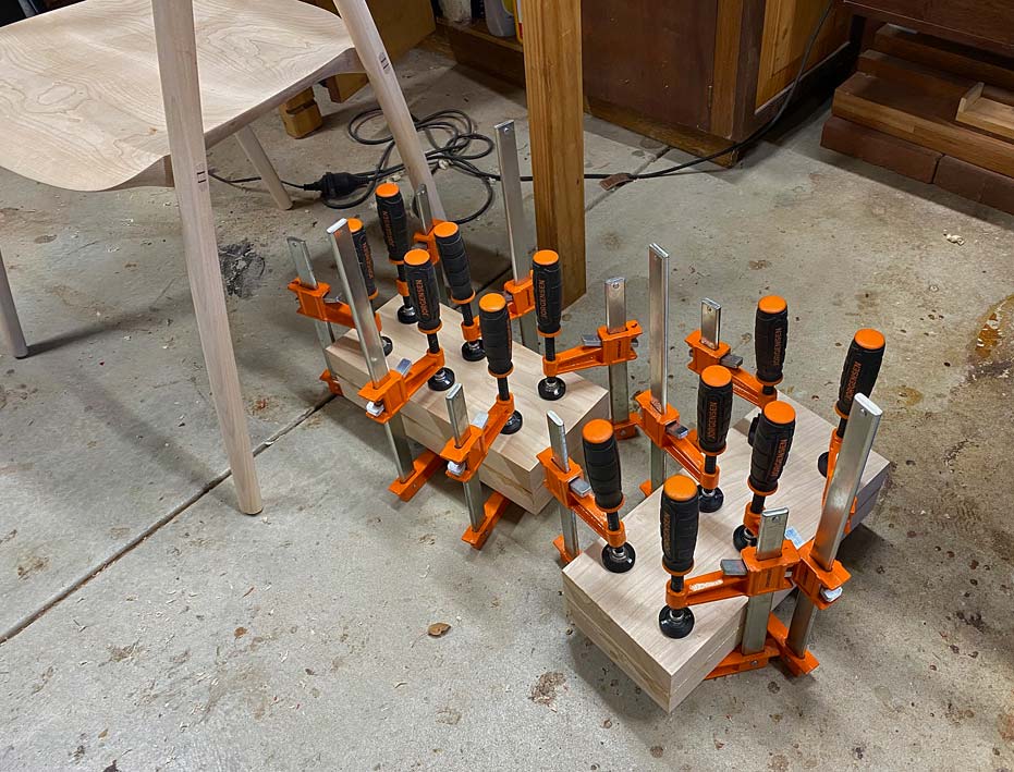
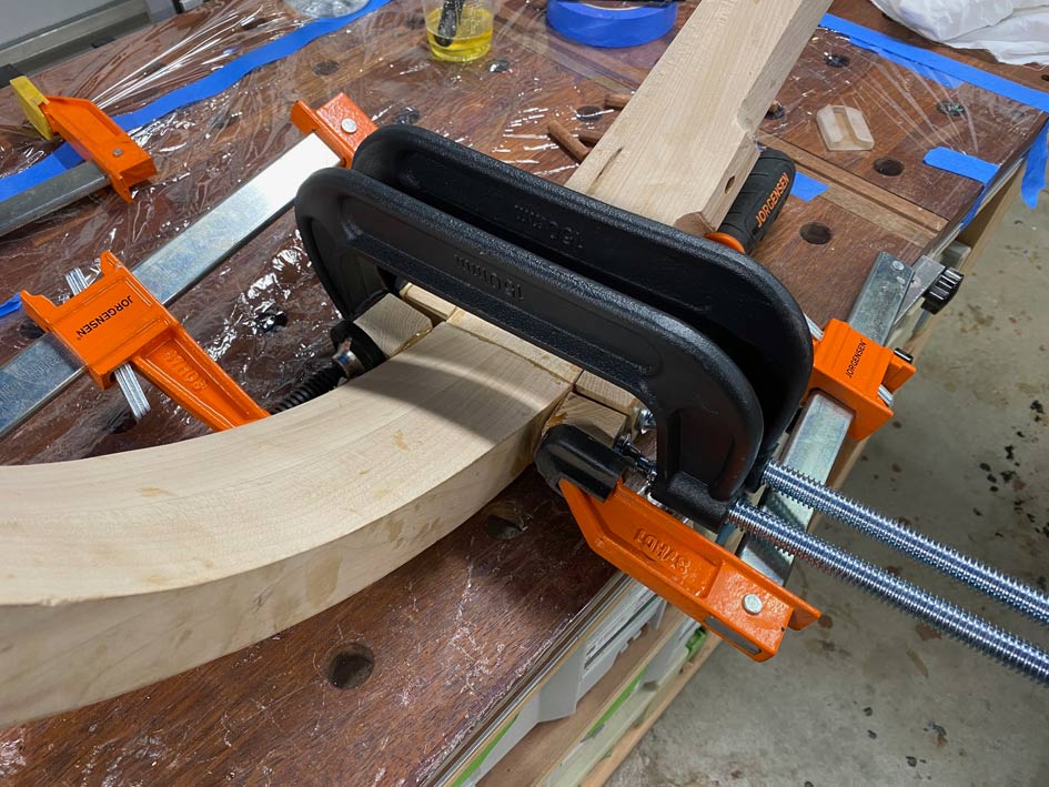
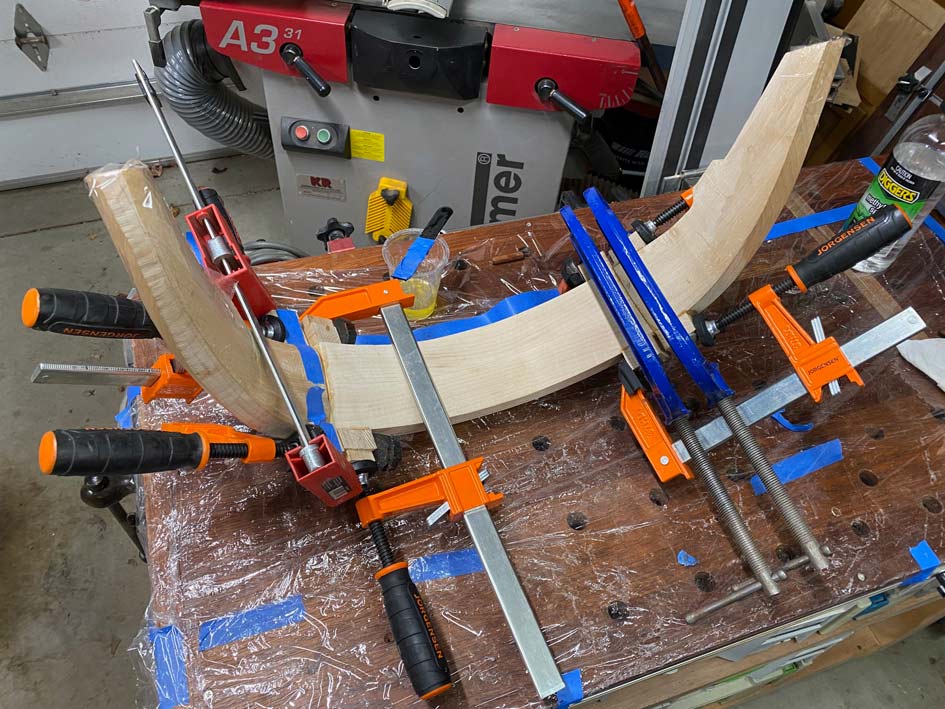
What happened was, in clamping the two parts, there was movement and an outside section moved slightly. This left a gap. To make it worse - as bad as it could get - the corner of one piece was crushed by a clamp, and cracked! I pushed it back into position, secured it, but it must have moved a little. Try not to cry ...

Well, you just have to repair it. And not with filler or a wedge.
I decided to peen the wood and move it into the gap. I have used this technique for
dovetails, which is edge grain, but never for end grain. In fact, I have not seen anyone do this before.
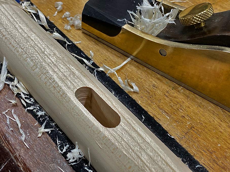
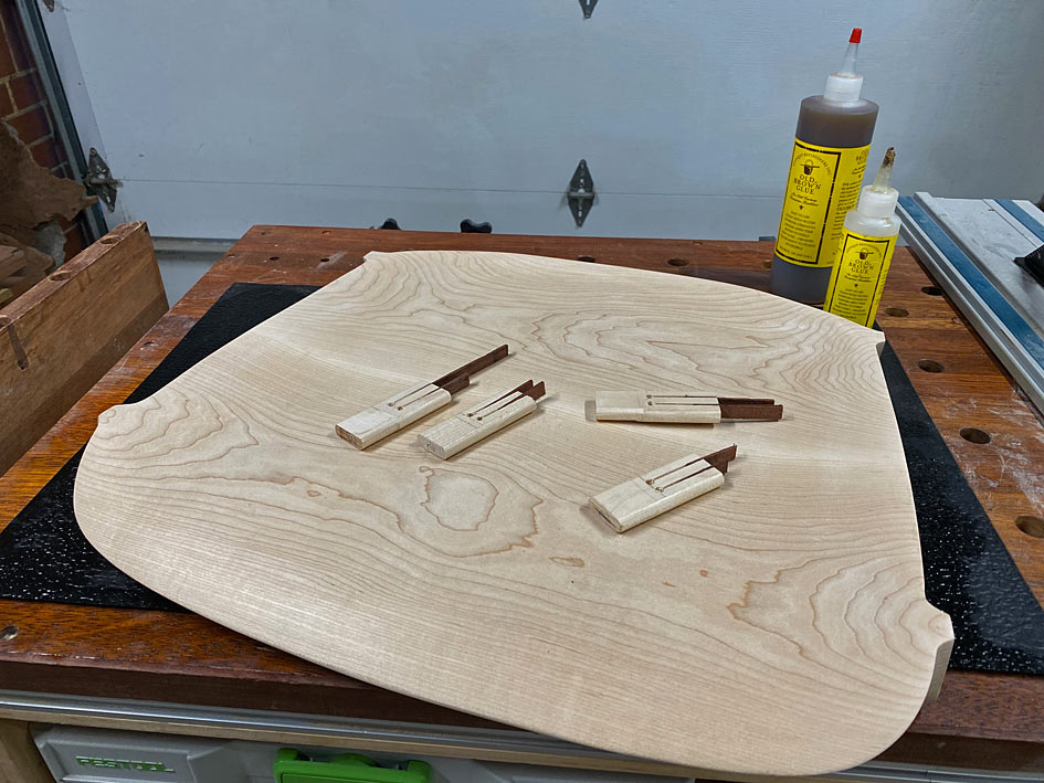
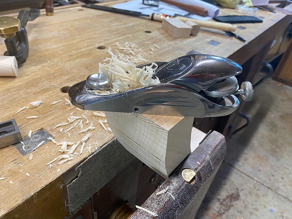
Using a couple of different size drift punches, I began tapping the wood into the gap ...
It looks like hell, but it did the job ...

I'll save the outcome for the end of the build. [wink]
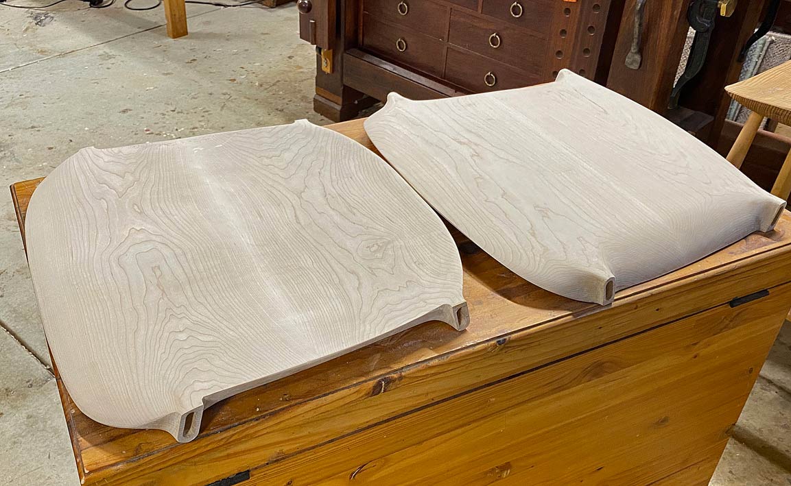
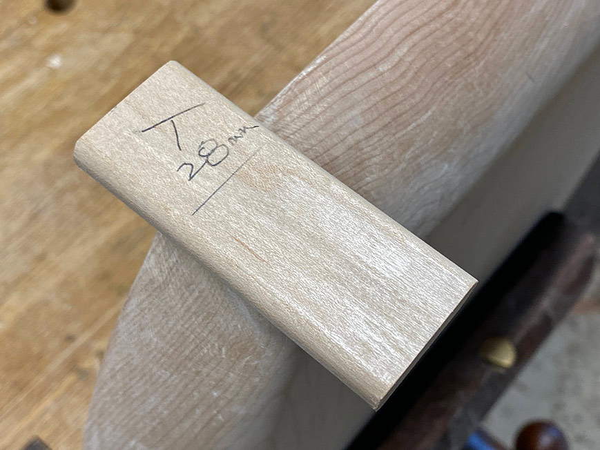
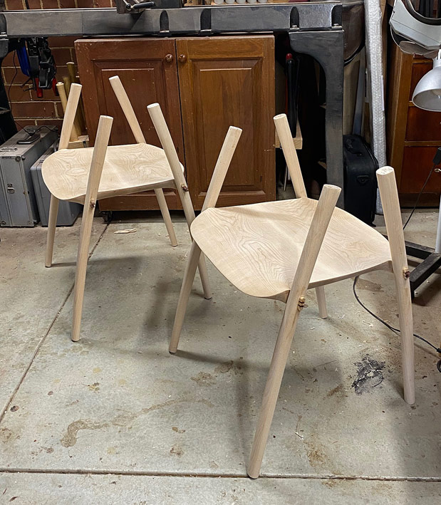
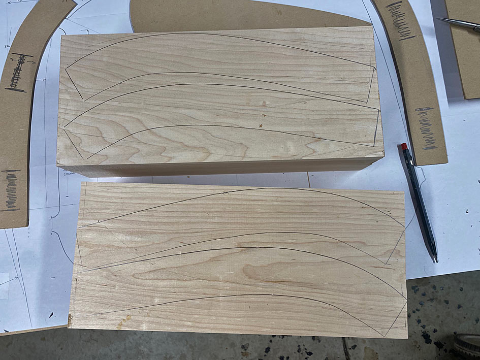
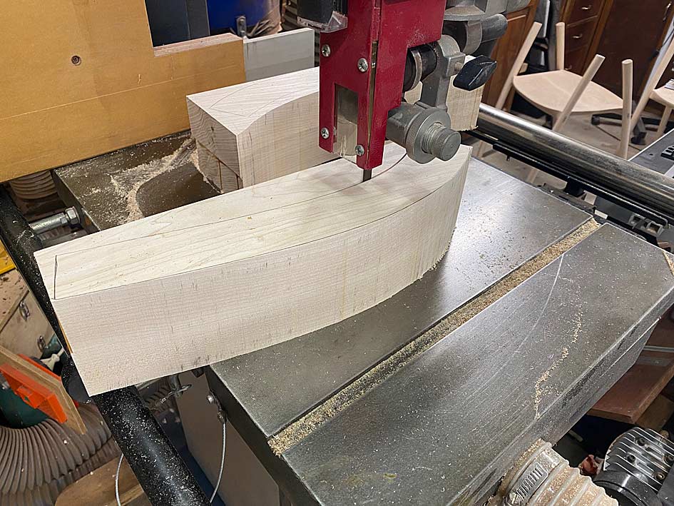
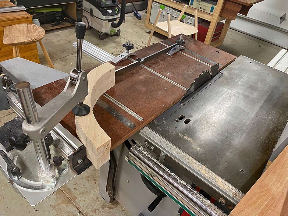
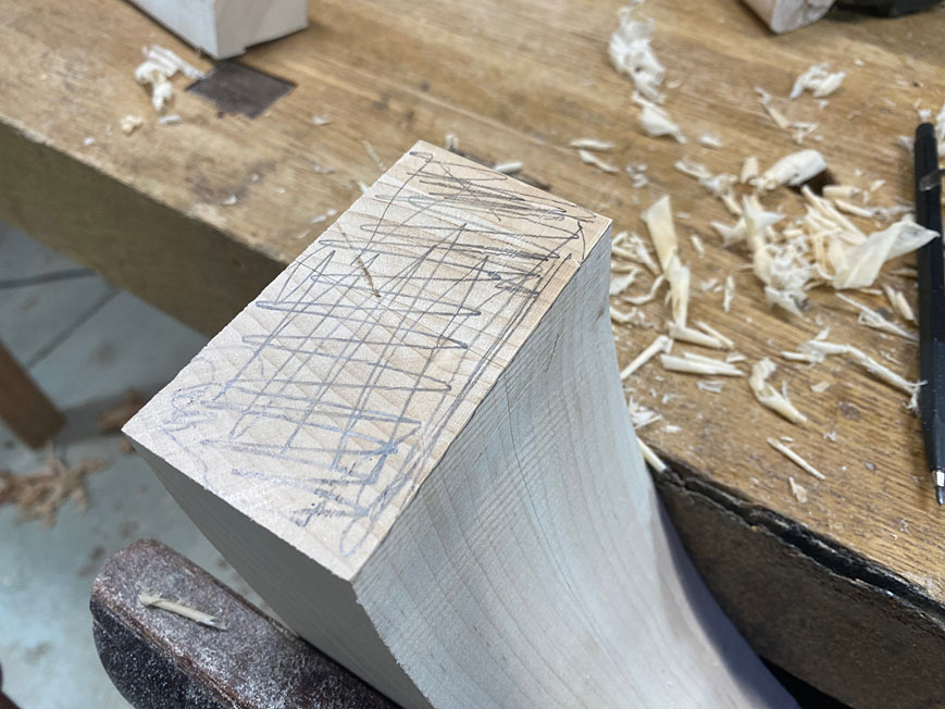
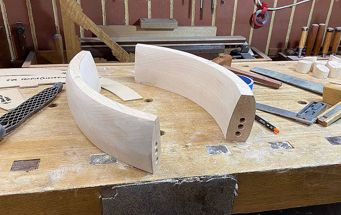
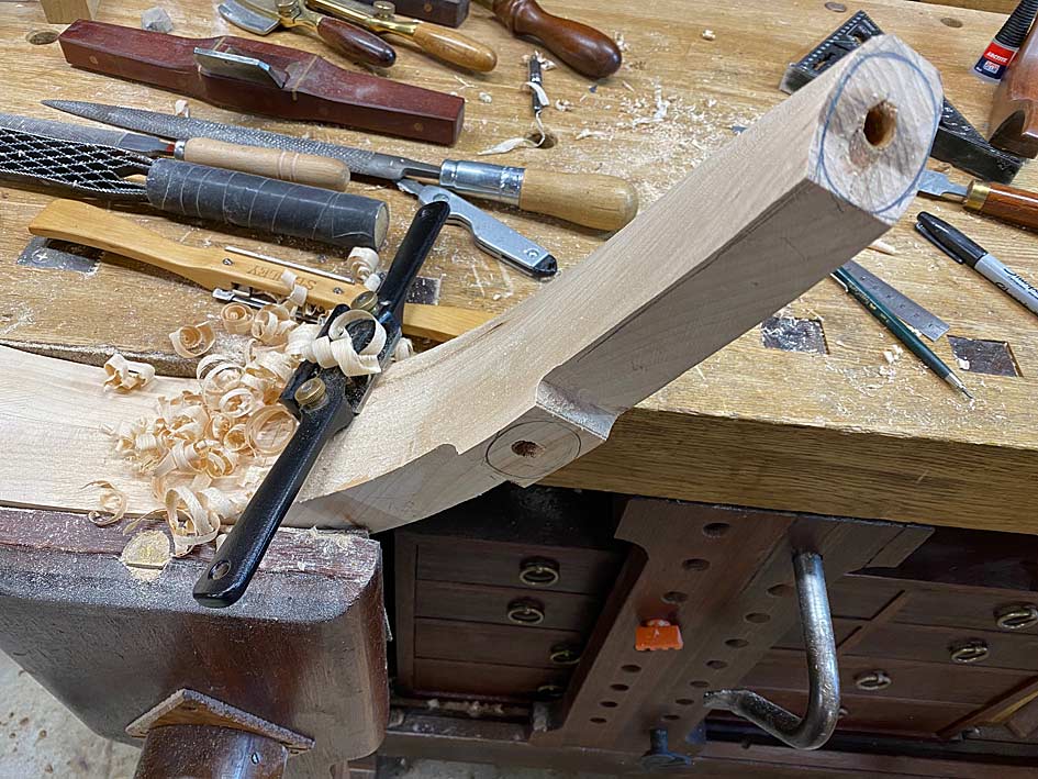
In the following photo you can see areas marked in pencil. These are where waste is to be removed ...

A little is removed, and then the arms are returned to the base, where more is marked for removal ...

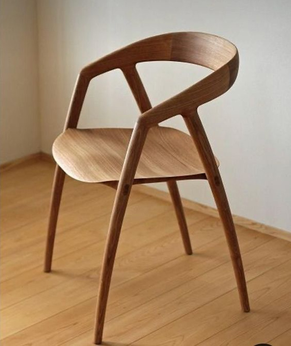
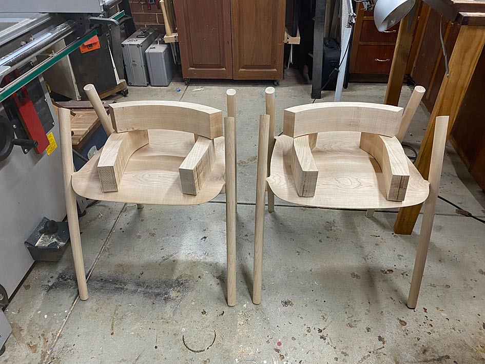
The shaping of the arms is completely by eye. There are no templates to guide the work done. The photos are my reference: "does it look right ... no ... take more off there ....".
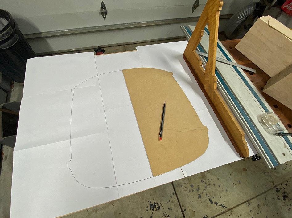
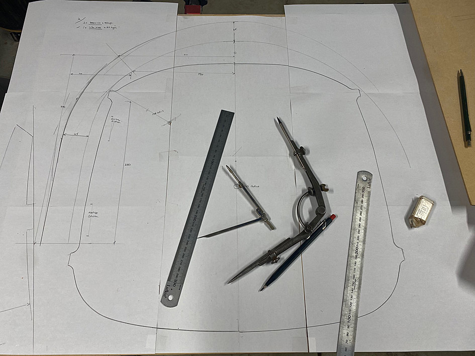
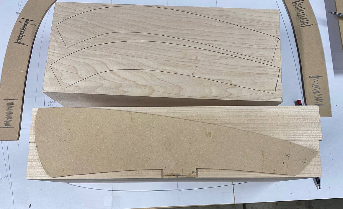
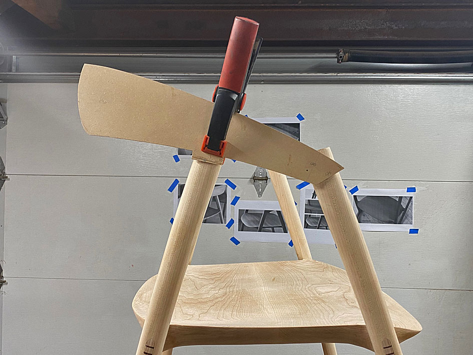
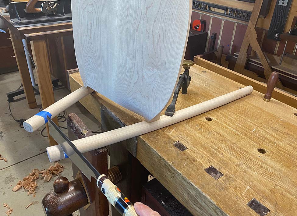
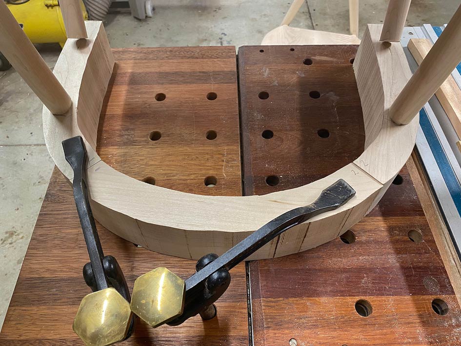
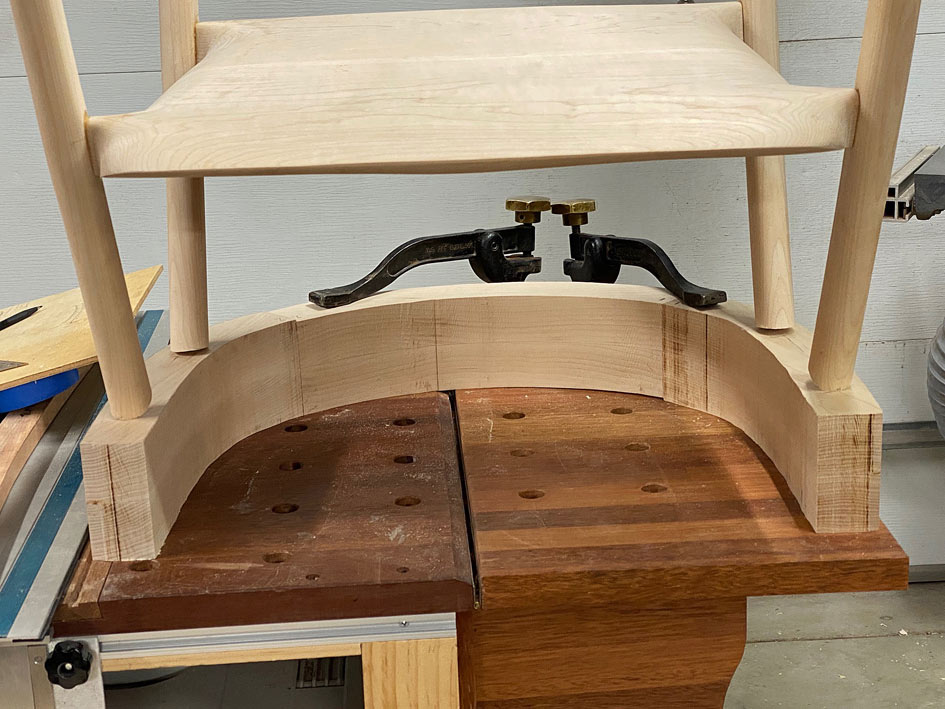
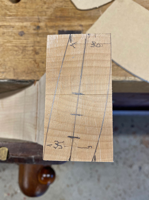
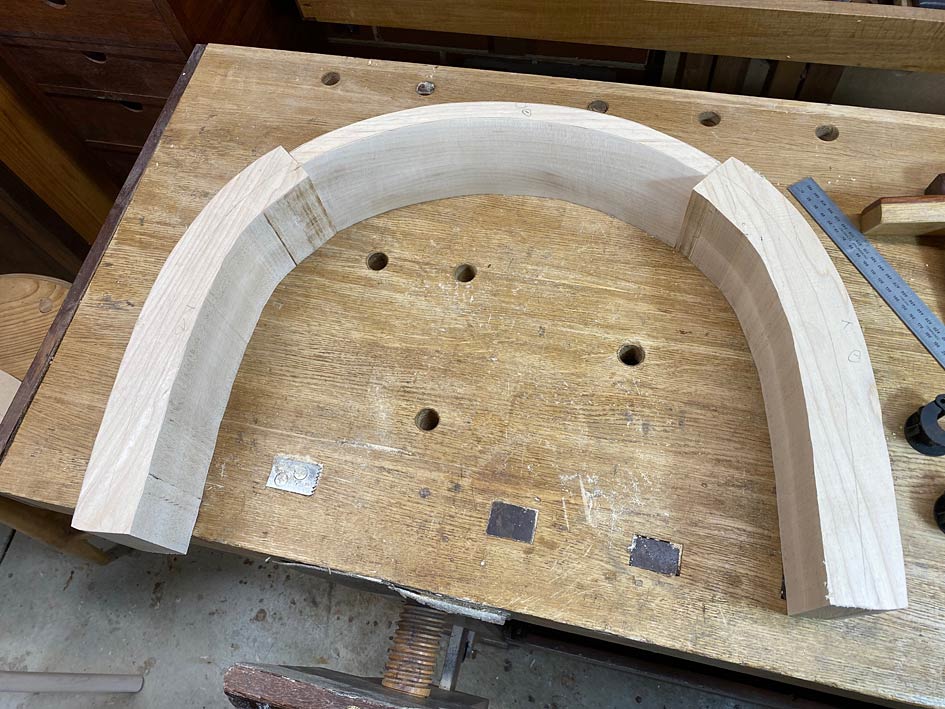
I finally get to a point where I need to check whether the curve at the rear is fair. It needs to be symmetrical and fair, and the same for both chairs. Now I trace the curve of one half of the rear centre section ...
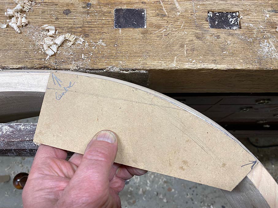
Flipping the template, this is taken to the other side of the back ..
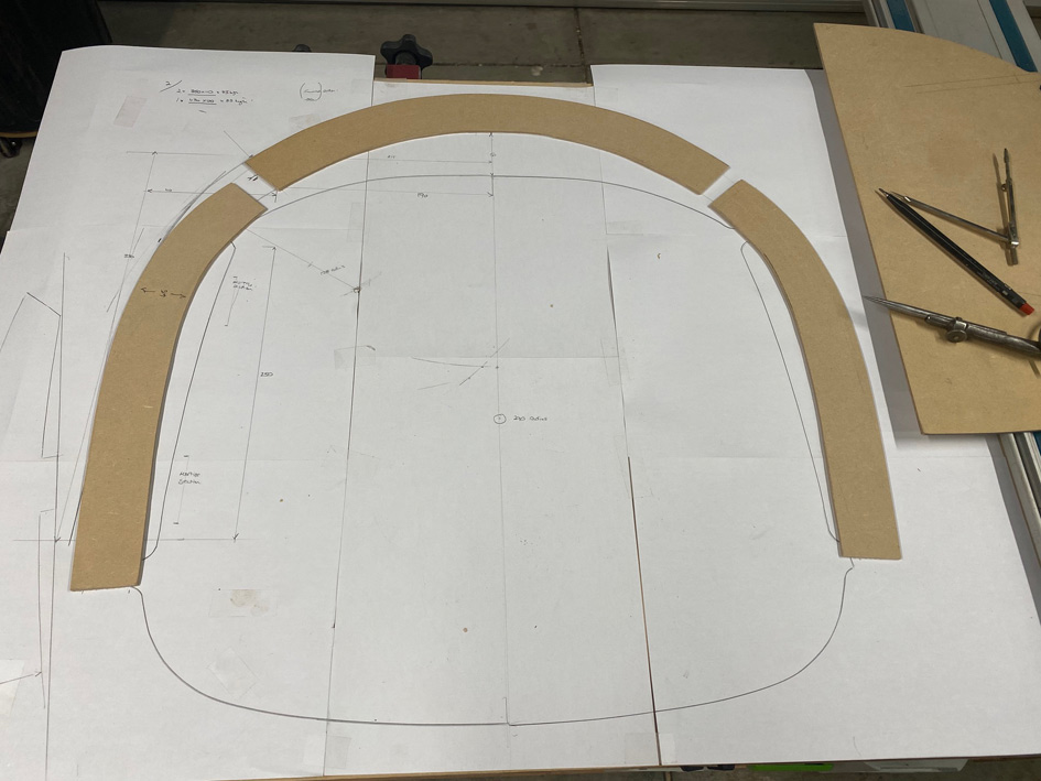
It is just a smidgeon off ...

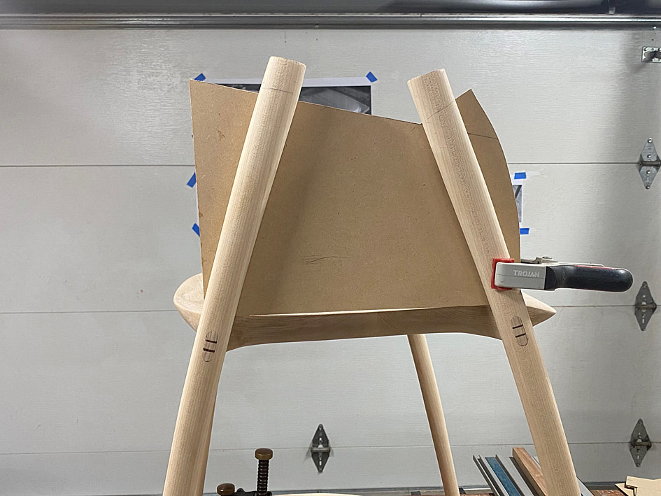
And the template is used on the other chair, and this proves to be identical o chair #1 ... just a smidgeon off the left side to spokeshave away ...
I am amazed that the shaping has remained within my tolerances all this time!
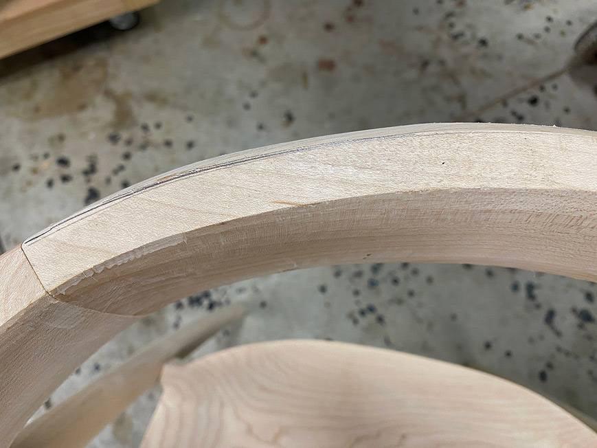
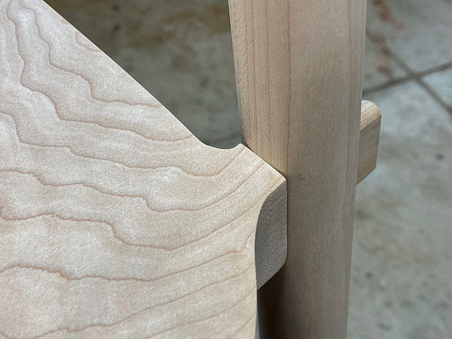
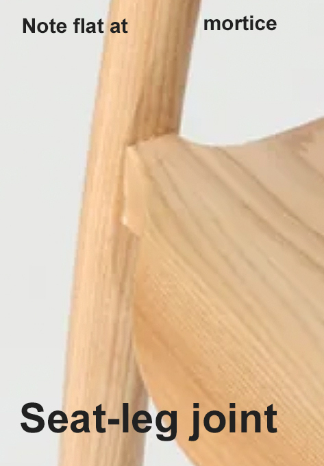
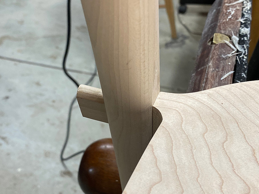
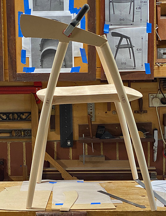
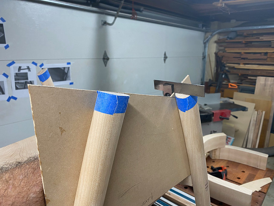
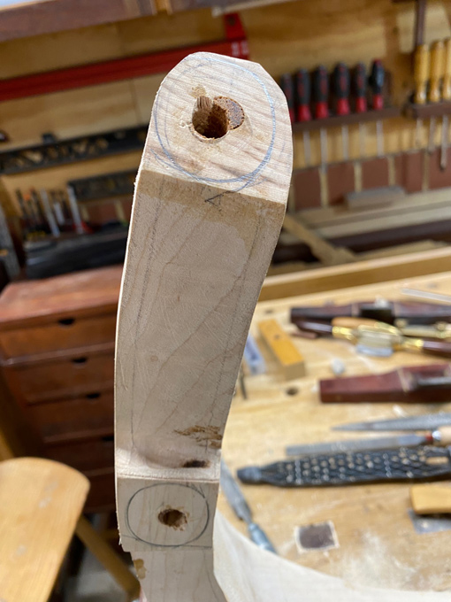
Lastly, I have been keeping an eye on the leg-arm joins. A couple were not meeting flush, and this needed to be corrected. For example, here you can see the gap. The blue tape marks where it keeps to be corrected ...

The top is covered in pencil to help see where the rasp is working, and the section that must not be touched ...

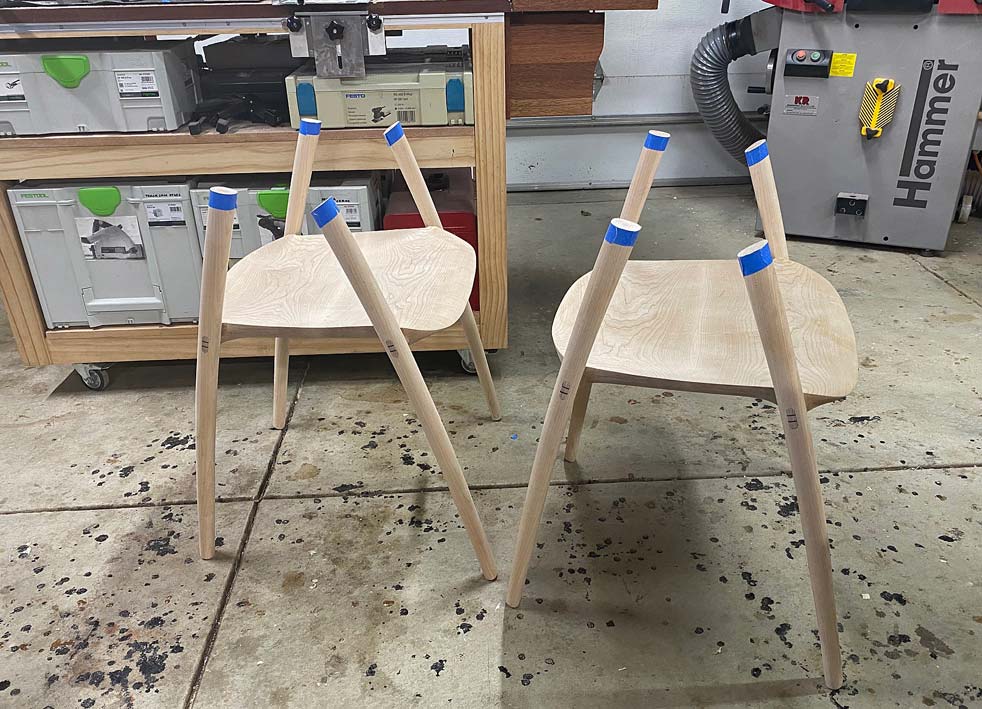
The result ...

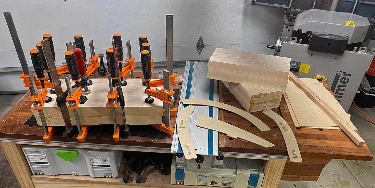
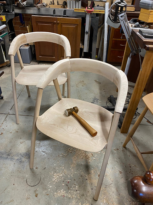
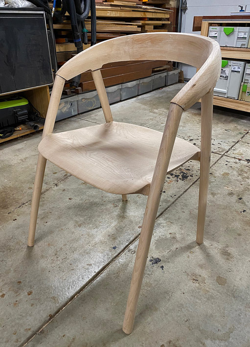
The end of the day. A lot of work has been done over a period of 1 1/2 days in the workshop. This may go unnoticed by all but you and I ...

Lots more to do.
Regards from Perth
Derek
")


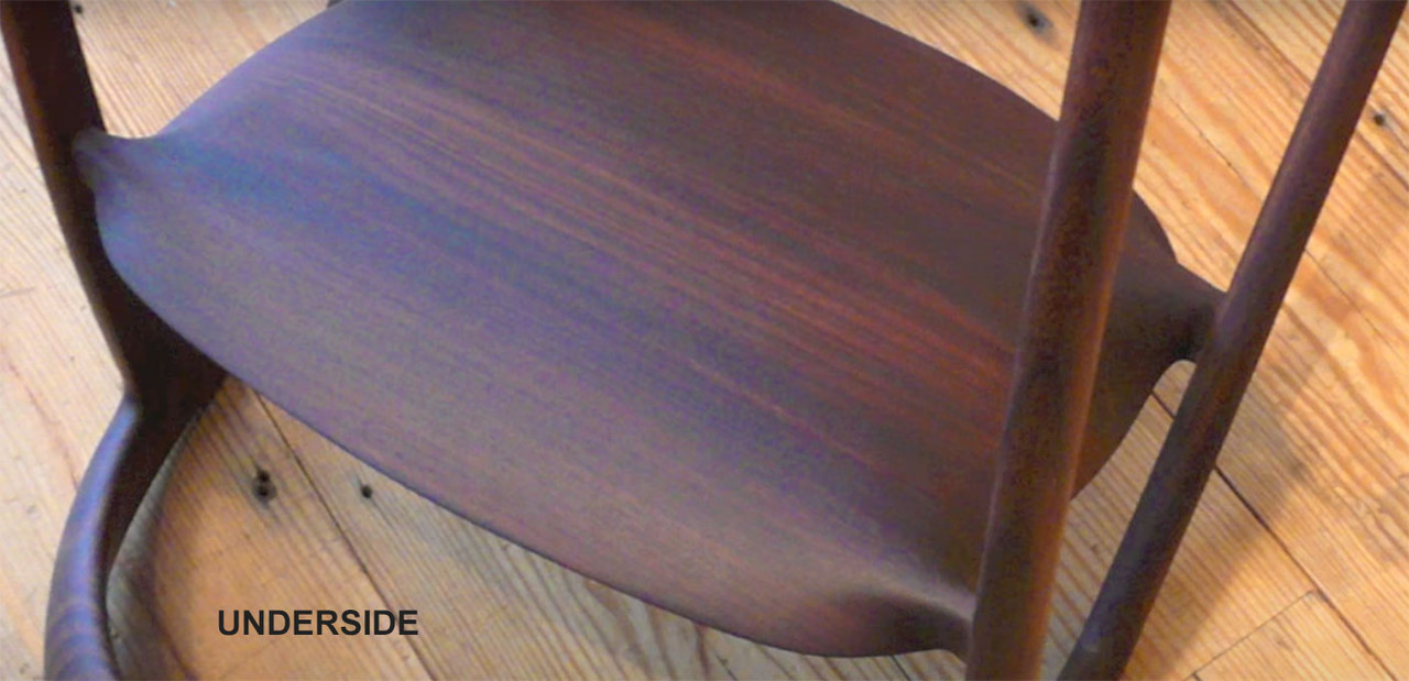
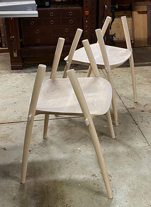
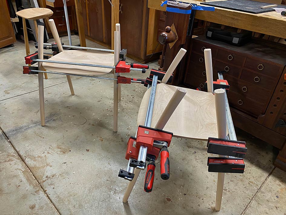
") The chairs were turned upside down on the arms ...
The chairs were turned upside down on the arms ...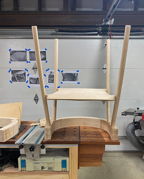

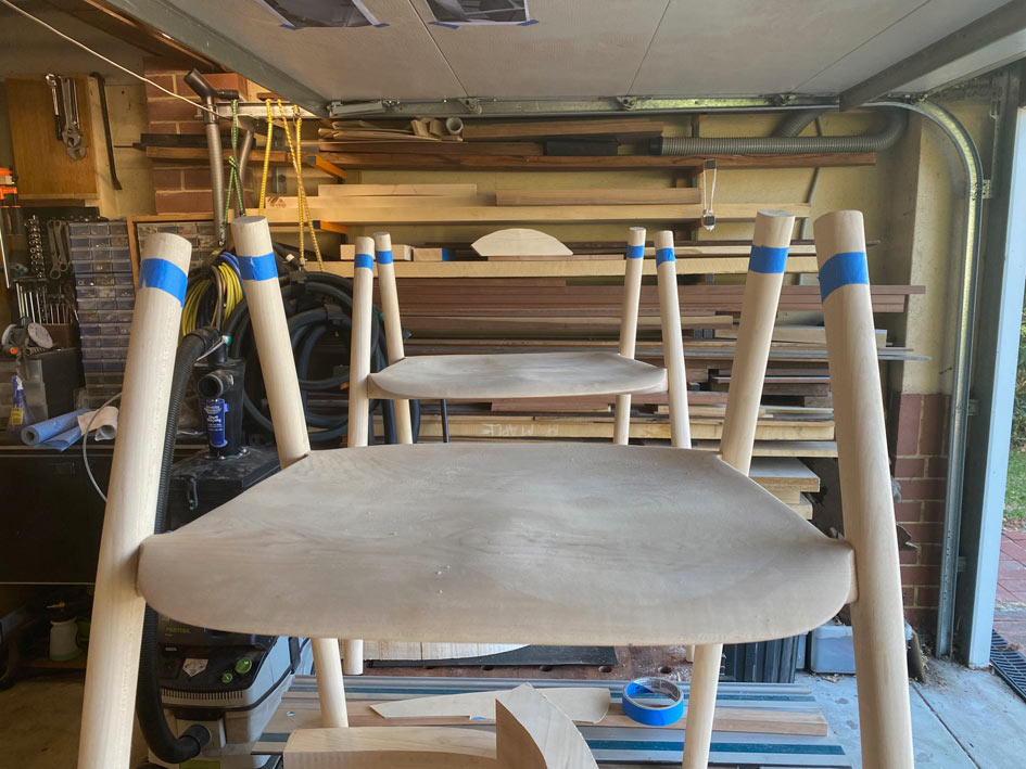


")