• Hi all and welcome to TheWoodHaven2 brought into the 21st Century, kicking and screaming! We all have Alasdair to thank for the vast bulk of the heavy lifting to get us here, no more so than me because he's taken away a huge burden of responsibility from my shoulders and brought us to this new shiny home, with all your previous content (hopefully) still intact! Please peruse and feed back. There is still plenty to do, like changing the colour scheme, adding the banner graphic, tweaking the odd setting here and there so I have added a new thread in the 'Technical Issues, Bugs and Feature Requests' forum for you to add any issues you find, any missing settings or just anything you'd like to see added/removed from the feature set that Xenforo offers. We will get to everything over the coming weeks so please be patient, but add anything at all to the thread I mention above and we promise to get to them over the next few days/weeks/months. In the meantime, please enjoy!

Drill press fence control using RC gearing parts

oddsocks

New Shoots
Joined
May 4, 2015
Messages
122
Reaction score
4
Location
Haverhill Suffolk
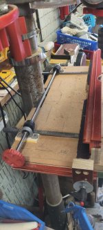
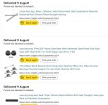
Its been a while (some years!) since I posted in the forum, but thought that my latest attempt to create an accurate adjustable drill press fence might be of interest. The picture really shows how it was built - I needed a 500mm length of '1MOD' gear track (which I cut in half to give 2 x 250mm), 2 x 1MOD gears, a 500mm length of 8mm stainless rod and a set of pillow bearings for them. Because it was via Amazon I ended up ordering more rod and pillow bearings than I actually needed but I'll eventually find a use for them. the total cost was £54.
drill press fence 1.jpg
I used my router table and fence to route 10mm wide channels in the fence (7mm deep)and the MDF baseboard (4mm deep). The gear track was drilled and screwed into the fence grooves and rides in the waxed MDF grooves. Once that was completed I just determined the packer height needed for the pillow bearings so that the gears had minimal slack. I can actually move the fence back and forth just by moving the gears, but for comfort I 3D printed a handle and fitted that to the end of the shaft.

Once in the required position the fence is locked into position by the turnlock that can be seen in the front right of the image (this was part of an earlier design, that had one of these at each end but as I tightened them the fence would move slightly - that doesn't happen now).

Now that its built I can see that if I'd bought 2 x 500 gear tracks (extra £18) I could have extended the MDF board to go either side of the pillar and put the pillow bearings and shaft behind the pillar. That would have allowed the fence to go back as far as possible, but in my experience of using the drill press, the fence has not needed to be that far back.

For info here's the item descriptions that I ordered:
amazon order.jpg
 
Interesting project thanks for posting.

I've never even considered a fence for my pillar drill apart from the one I have across the back parallel with the pillar, at risk of looking stupid, what do you use it for? I can't think of anything in my own circumstances where I'd need one so open to ideas.
 
Interesting project thanks for posting.

I've never even considered a fence for my pillar drill apart from the one I have across the back parallel with the pillar, at risk of looking stupid, what do you use it for? I can't think of anything in my own circumstances where I'd need one so open to ideas.
Making one of these perhaps?
20230218_132010_resized.jpeg
 
Interesting project. Do you get any problems with swarf building up in the tack teeth?
I tend to use it for wood, but when I do drill metal it's normally lower than the fence and my extractor takes it away. To be honest though I've not drilled anything yet since building it earlier this week
 
Interesting project thanks for posting.

I've never even considered a fence for my pillar drill apart from the one I have across the back parallel with the pillar, at risk of looking stupid, what do you use it for? I can't think of anything in my own circumstances where I'd need one so open to ideas.
I recently made a tall 'flatpack' shelving unit and drilling the holes for the pegs and turnlocks needs to be really accurate. My old method would move slightly when positioning the wood and that was visible
 
As per Andy's reply. repeat drilling of holes in line. My fence runs in tee slots on the drill table with bristol levers to lock in any desired position. IMHO there is no need to have it move parallel as in the OP.
Bristol levers ...that's the term I couldn't remember last night! Yes agreed there's no need for it to run parallel, but having the two slots a good running fit and the gears slack free helps stop any movement when sheet material etc is put into position. In my old solution just knocking the fence with the wood when lining it up would cause it to move.
 
Yes I see how that would be very useful though for the odd occasions In my situation it would be overkill. (y) Did you turn the brass pins as well?
 
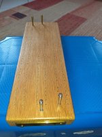
No Bob, that was made back in 1997 when I was working and hanging around with with some clever engineering types. There are three brass and three steel pegs ( one for spare ). I did make the brass gate that holds the pegs in when not in use and filed down a brass screw to make it look like it was riveted. We still use it and I like to think helped my kids with their maths back in the day.
 
You do know that you need to make one for each of the kids or they'll fight over it when the time comes :)
 
let them fight. I’m not making three of everything.:). And surely the value increases with scarcity.
:ROFLMAO: A man after my own heart. My 2 kids have dibs on certain items and I don't care as I won't be around to witness the fighting.
It has reminded me however we have a family history album going back aways and there's only one copy so I really need to get around to duplicating that, and updating it.
 
Its been a while (some years!) since I posted in the forum, but thought that my latest attempt to create an accurate adjustable drill press fence might be of interest. The picture really shows how it was built - I needed a 500mm length of '1MOD' gear track (which I cut in half to give 2 x 250mm), 2 x 1MOD gears, a 500mm length of 8mm stainless rod and a set of pillow bearings for them. Because it was via Amazon I ended up ordering more rod and pillow bearings than I actually needed but I'll eventually find a use for them. the total cost was £54.
View attachment 28059
I used my router table and fence to route 10mm wide channels in the fence (7mm deep)and the MDF baseboard (4mm deep). The gear track was drilled and screwed into the fence grooves and rides in the waxed MDF grooves. Once that was completed I just determined the packer height needed for the pillow bearings so that the gears had minimal slack. I can actually move the fence back and forth just by moving the gears, but for comfort I 3D printed a handle and fitted that to the end of the shaft.

Once in the required position the fence is locked into position by the turnlock that can be seen in the front right of the image (this was part of an earlier design, that had one of these at each end but as I tightened them the fence would move slightly - that doesn't happen now).

Now that its built I can see that if I'd bought 2 x 500 gear tracks (extra £18) I could have extended the MDF board to go either side of the pillar and put the pillow bearings and shaft behind the pillar. That would have allowed the fence to go back as far as possible, but in my experience of using the drill press, the fence has not needed to be that far back.

For info here's the item descriptions that I ordered:
View attachment 28058
Neat
 
Back
Top