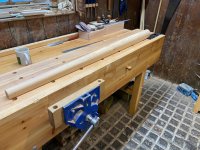
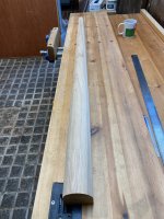
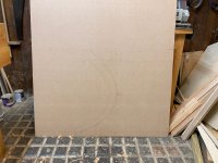
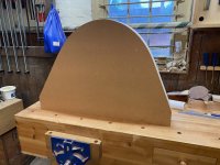
• Hi all and welcome to TheWoodHaven2 brought into the 21st Century, kicking and screaming! We all have Alasdair to thank for the vast bulk of the heavy lifting to get us here, no more so than me because he's taken away a huge burden of responsibility from my shoulders and brought us to this new shiny home, with all your previous content (hopefully) still intact! Please peruse and feed back. There is still plenty to do, like changing the colour scheme, adding the banner graphic, tweaking the odd setting here and there so I have added a new thread in the 'Technical Issues, Bugs and Feature Requests' forum for you to add any issues you find, any missing settings or just anything you'd like to see added/removed from the feature set that Xenforo offers. We will get to everything over the coming weeks so please be patient, but add anything at all to the thread I mention above and we promise to get to them over the next few days/weeks/months. In the meantime, please enjoy!

Kitchen Table - Finished!

NickM

Old Oak
Joined
Dec 8, 2020
Messages
1,537
Reaction score
843
Location
Near Basingstoke
This is a project I've been thinking about for a little while. I spent some time before Christmas working on the design and doing some experimentation but I haven't done much this month due to a shoulder injury and a bout of shingles (not recommended...). However, I'm getting back into it now. Progress is likely to be glacial though as I've just started a temporary part time job.

The main design features I want to incorporate are an oval top, because it lends itself to the fairly tight space I'm working with, and pedestal legs to avoid legs getting in the way of chairs/knees etc.

I started off by making a mock up of the table top out of a piece of hardboard. This was to help decide how big the table could be.
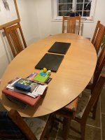
IMG_2699.jpeg

As you can see, it's a little wider and longer than our current rectangular table. We'd normally have 6 chairs around it, but could seat 8. It's fairly tight, but not as bad as it looks in the photo.

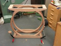
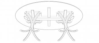
Taking inspiration from some of the work I saw when I was at Edward Barnsley, I wanted curved pedestal legs tapered in all dimensions. After playing around with a few alternatives and drawing them in Fusion 360 (a huge test of my very rudimentary CAD skills), I settled on this design.
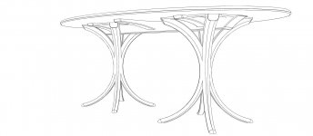
Kitchen Table 1.jpg

Kitchen Table 4.jpg

The second drawing shows how the legs in each pedestal will be tied together at the top by a brass 'square' (let in to the tops of the legs) and a long stretcher and cross rails.

I haven't settled on choice of wood for this yet, but I think the 'undercarriage' will be made from oak not least because it bends well. I might make the top from oak, but I'm also considering sycamore for a lighter colour (our kitchen is quite dark). It's likely to come down to what I can find when I start trawling timber yards.

You might also be wondering about chairs. They're for the future...
 
NickM":2804u2ug said:
some of the work I saw when I was Edward Barnsley

Alter ego? :lol:

Sorry: couldn't resist.

Seriously though, this sounds like it's going to be a very interesting project.
 
Dr.Al":2av63d47 said:
NickM":2av63d47 said:
some of the work I saw when I was Edward Barnsley

Alter ego? :lol:

Sorry: couldn't resist.

Seriously though, this sounds like it's going to be a very interesting project.

Good spot. It was actually a former life. I believe in reincarnation! I'll edit that...
 
I got some advice on the design, and one of the concerns was whether the legs would effectively be big 'springs'. For instance, if someone pushed down on the table edge as they got up and then let go, would wine glasses be catapulted across the room?!

The advice was to do some experiments by making legs with the same cross-sectional profile but straightened out to see how much flex they would have. I made one out of solid wood and one laminated. They're longer than the actual leg would be to simulate the leverage created by the table overhang.

This is the solid wood version:

IMG_2706.jpeg

IMG_2705.jpeg

I don't have a photo of the laminated version. I'll try to add some more detail about making the laminations later in the project. However, it's worth noting at this stage that each lamination is tapered - from 1.5mm up to 3.5mm. There are 20 laminations in each leg so the legs taper from 30mm to 70mm from bottom to top but with continuous laminations and no grain run out. I made these by constructing a tapered sled which I could run through my thickness planer. When I come to make the actual legs, I'll probably use my drum sander rather than the thicknesser (or perhaps a combination) because the thicknesser was a bit hit and miss - sometimes ripping out chunks as the thin strip curved up a bit...
I tested their flex by putting one end in the vice and giving it a push. Whilst there was some flex, it took a fair bit of pushing and, really, they felt pretty rigid to me so I decided to have a go at making a curved version.
At this point, I'm using bits of oak that I've salvaged from various places so it hasn't cost me anything.
 
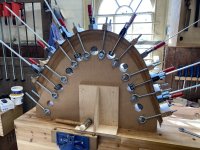
To make the curved legs, I had to make a former to bend them on.

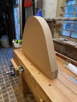
I started by doing a full-size drawing on some MDF.

IMG_2720.jpeg

I drew the leg shape by plotting out some registration points and then bending a steel ruler through the points. You need two people or three arms to be able to do this. Needless to say there was a fair bit of trial and error before I found a shape I was happy with.

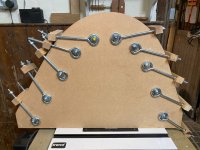
Once I was happy with that, I cut out the inside curve of the leg and carefully spokeshaved down to the line. I used that as a template to rout more layers which I could then glue together to make the mould:

IMG_2721.jpeg

IMG_2722.jpeg

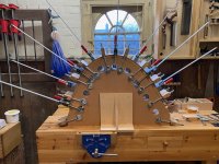
I added some eye bolts and made wooden clamping blocks which could be bolted down.

IMG_2733.jpeg

The dry runs I did unfortunately weren't very good as I couldn't clamp it up with out getting gaps in the laminations. I decided to cut large holes in the mould so that I could use additional clamps. Doing that, and only laying down a few laminations at a time (6 to 8), I seemed to be able to get it gap free.

IMG_2782.jpeg

It's still not perfect and I'd appreciate input on how to improve things, but I'll post the question in a separate post as I expect most people will have given up reading this one by now...

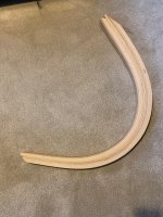
This is the result:

IMG_2785.jpeg

As I say it's not perfect, but most of the imperfections are from poor preparation of the laminations (thicknesser not leaving a great finish for example) or defects in the wood I was using (I think one of the gaps was from a key hole in the oak door I cut up!).

However, most importantly, the leg feels really stiff to me. I can put all my weight through the curve and can't feel any noticeable deflection. This has given me the confidence to carry on with the design.
 
I'd really appreciate some advice - especially from those of you who have done this sort of lamination work before.

I think the main problem with the experiment I've done is that the outside of the curve is uneven because of depressions caused by the clamps.

In an ideal world, I think it would be best to make laminations using male and female moulds as that should give an even clamping pressure across the whole surface. However, I don't think that's possible here because: (a) it would be very difficult to make a perfect female mould as the curve isn't the radius of a circle and the tapering in the laminations mean there are too many variables that, if slightly out, would mean the moulds wouldn't close up properly; and (b) I'd need to do the whole lamination in one go (or have several female moulds for different numbers of the laminations - that's too much work) and I don't think it would be possible to clamp up the mould on 20 laminations - they're too stiff.

I therefore think I need to fine tune the method I'm using.

One improvement would be to use better clamping cauls. If this was a straight lamination, I'd use a couple of bits of thick strong wood to spread the load of the clamps. However, strong thick bits of wood don't bend so what can I do? For this experiment, I used three layers of 3mm MDF/hardboard/cardboard type stuff. I think it helped to a degree, but it had a tendency to bulge out between the clamps and didn't really spread the load. Are there any other materials I could use?

Would thin layers of oak be better? In effect, I'd just have some extra laminations which wouldn't be glued on (they wouldn't need to be tapered though). How thick should they be and how many should I use?

I've even wondered whether a length of steel would be an option if I could bend it to approximately the right shape. It wouldn't need to be the perfect shape, as my hope would be that it would have enough flexibility to find the right shape as it's clamped up. Any merit in that?

The only other improvement I can think of is to use even more clamps. I might be able to fit a few more in I suppose!

One other problem I had was keeping the laminations lined up and, therefore avoiding twist. I think I can solve that one by making the laminations the same width as the mould and making guide rails to keep them in the right place (or relying on the eye bolts as guide rails).

As a final aside, I used cascamite for this. I really used it because I had some already (including some which might have been from the period when it wasn't very good). It seemed to work well and I'll stick with some sort of UF glue for the actual build.
 
There's a bit of crossover here between what you're doing and what I do.

Would you consider steaming your lamination strips in a home made steamer?

I think some of the issues you've found could be overcome by anchoring the leg at one end of the former and winching the other end round in a smooth movement before clamping, if it were needed. That would allow the laminations to slide against eachother without gapping as they were winched around the former.

I have even seen on YT the work piece anchored/clamped at the centre of the arc and the workpiece winched round at both ends at the same time like and archer's bow.
 
The flexibility of a beam (aka one of your laminations) varies with the cube of the thickness.
Reducing the thickness by a small amount soon makes them more flexible, this and possibly wetting or steaming as suggested above could well help your glue up even though there may be a few extra laminations.

If you dont want to reduce thickness, then wet/steam them and form on your jig until dry. Mark a V across the edges of the lamination stack to indicate the order they were bent in and then glue together. Being ready bent, far less clamping pressure should be needed.

Bob
 
I have done a bit of laminating in the past, and I can say it’s going very well really! You’re doubts are par for the course! Yes you’re right these are hugely strong shapes when glued up. In this case I would start to apply pressure at the top and work away towards each end.
I don’t think that this shape will lend itself to a 2 part mould system as easily as some, and these are quite substantial glue ups. Lumps, well that just needs some of the load spreading, a spring steel band was used, but I’ve never had one, particularly as the width needs to be suitable to each job or it gets in the way.
I think I would try to make a protective strip of Oak about 6-8 mm thick to even out the cramps pressure, the bend isn’t excessive so it should be possible to use boiling water on the Oak and then gradually bend it to the shape, it might need a couple of attempts, but just go steady with it as the fibres in the wood need time to move as it curves - as you tighten up.
It might be of benefit to put a socket on your electric drill to whizz up the nuts on the impressive cramps you’ve got!
These things are always a developing experiment till you end up getting it right, and as I said it’s going well up to now.
How thick are the laminations you are using? Looking at the profile I think you could probably get away with 4mm?
I cut mine about 6” longer than needed so that the back end could be cramped to the bench allowing each strip to be hand planed.
Best of luck. Ian
Edit, twisting you could use wedges between the edges of the laminations and the eyebolt thingies.
 
Malc and Bob, I think you're both on to something with trying to pre-bend the laminations by steaming them. I think if I can get them close/er to the final shape before gluing, I may be able to use a little less clamping pressure which will help with some of the issues I've been having.

When I first started thinking about this project, I did wonder if I'd need to steam the laminations. However, I was thinking about that from the perspective of avoiding them cracking and, when I realised it was possible to bend them around the former without cracking I completely forgot about steaming.

It's potentially extra work, but it might actually allow me to glue all the layers in one go and that could save time in the long run.

Thanks for your input.
 
Cabinetman":24gll8u2 said:
I think I would try to make a protective strip of Oak about 6-8 mm thick to even out the cramps pressure, the bend isn’t excessive so it should be possible to use boiling water on the Oak and then gradually bend it to the shape, it might need a couple of attempts, but just go steady with it as the fibres in the wood need time to move as it curves - as you tighten up.

Steam bending a thicker oak clamping caul is a good idea. It will give me a lot more load spreading than I currently have.

Cabinetman":24gll8u2 said:
It might be of benefit to put a socket on your electric drill to whizz up the nuts on the impressive cramps you’ve got!

That crossed my mind too. I need to check if I've got a deep socket that will fit and which I can mount on my drill. I've got some spark plug sockets so hopefully one of them will be the right size.

Cabinetman":24gll8u2 said:
How thick are the laminations you are using? Looking at the profile I think you could probably get away with 4mm?

They're 3.5mm at the thick end, down to 1.5mm.

Cabinetman":24gll8u2 said:
I cut mine about 6” longer than needed so that the back end could be cramped to the bench allowing each strip to be hand planed.

I will be making them longer than needed, but won't be hand planing each lamination. There are going to be 160 laminations in total so it would be a lot of work, even if the hand planing is only to clean up the final surface. My plan is to finish each lamination by passing it through a drum sander. I can do a final pass with pretty fine abrasive which should give a good enough surface for glue up.

The length of the laminations, how they're tapered and how they're mounted on the former is something I need to keep very consistent so that so that the tapering of the leg is the same each time (e.g. they should each be the same thickness at the foot end). That won't be hard, but I just need a clear process and remember to follow it!
 
Nick, I wasn't proposing pre-bending with steaming, although that is similar to how I bend an instrument side which springs back somewhat when cold, then laminate with veneers and clamp in a form to assume the final shape.

Now I think about it, that seems to be the only way. I would still suggest after steaming to use the 'archer's bow' method, or the anchor at one end and winch the other before clamping.

The bodgers in the woods used to force the arm of a Windsor chair by locking pins around the curve as they progressed the bend from one end to the other. But they were pulling the arm, like winching, before each pin locked the shape.

Not that I'm old enough to remember seeing them do that. Honest. :)
 
NickM":ktcdadwz said:
I'd really appreciate some advice - especially from those of you who have done this sort of lamination work before.
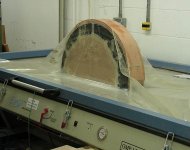
No idea what your finances are like, but if they could stand the cost of a vacuum bag system I suspect your job would be relatively straightforward, similar to below which was laminated 2 mm cherry constructional veneers glued with slow setting epoxy resin. Each glue-up was wide enough to split into two arced laminates, so just two glue-ups were enough for all four arcs that made up the two almost complete circle circumferences. I suspect you may be able to do something similar, e.g., glue and bend laminates wide enough to get out more than just one leg at a time. Slainte.

AD-Table17-650px.jpg

AD-Table14-650px.jpg

AD-Table33-650px.jpg
 
Right you’re using a drum sander, I’ve never even seen one of those, you said that each laminate will decrease in thickness along its length, can you do that on one of those? As that’s a whole new level of "how on Earth do you produce those"? Except by hand planing. So there are 20 strips per leg, x 3.5 is 70mm at the thick end and down to 30mm at the thin end?
I suspect most people would make it 70 (that seems quite thick) all the way through and then cut it back to the required shape after gluing.
I am sorry to sow doubts but this is me not wanting to keep silent and watch a problem unfold. Ian
EDIT, yes you said all this at the beginning, just re read it, sorry, well you certainly don’t shy away from difficulty!
 
Cabinetman":354fhfxk said:
Right you’re using a drum sander, I’ve never even seen one of those, you said that each laminate will decrease in thickness along its length, can you do that on one of those? As that’s a whole new level of "how on Earth do you produce those"? Except by hand planing.

Think of the drum sander as a thicknesser. The taper is achieved by putting the lamination on a tapered sled which passes under the sanding drum. I made the sled by carefully planing two runners with the right taper in them.

Cabinetman":354fhfxk said:
So there are 20 strips per leg, x 3.5 is 70mm at the thick end and down to 30mm at the thin end?
I suspect most people would make it 70 (that seems quite thick) all the way through and then cut it back to the required shape after gluing.

That's correct. It is quite thick, but it's a fairly substantial table and whilst I want the legs to look light and elegant, I don't want them to appear too 'weedy'. Cutting the taper afterwards would cause grain run out. If goes to plan, I'll have tapered legs but with the laminations running continuously the whole length.

They're tapered width-wise as well and that will be done afterwards.[/quote]
 
Malc2098":3bvr0qpf said:
Nick, I wasn't proposing pre-bending with steaming, although that is similar to how I bend an instrument side which springs back somewhat when cold, then laminate with veneers and clamp in a form to assume the final shape.

Now I think about it, that seems to be the only way. I would still suggest after steaming to use the 'archer's bow' method, or the anchor at one end and winch the other before clamping.

The bodgers in the woods used to force the arm of a Windsor chair by locking pins around the curve as they progressed the bend from one end to the other. But they were pulling the arm, like winching, before each pin locked the shape.

Not that I'm old enough to remember seeing them do that. Honest. :)

Thanks Malc. I was trying to pull the laminations around before tightening each clamp, but I think that will be easier if I've steamed them first. There was quite a lot of resistance. I was also doing it by myself and didn't really have enough arms. Maybe a ratchet strap would help.

What you describe with your instrument sides is exactly what I'm now contemplating.

One thing I was pleased about with my experiment is that there was almost zero spring back.
 
Richard":jfpc01ab said:
NickM":jfpc01ab said:
I'd really appreciate some advice - especially from those of you who have done this sort of lamination work before.
No idea what your finances are like, but if they could stand the cost of a vacuum bag system I suspect your job would be relatively straightforward, similar to below which was laminated 2 mm cherry constructional veneers glued with slow setting epoxy resin. Each glue-up was wide enough to split into two arced laminates, so just two glue-ups were enough for all four arcs that made up the two almost complete circle circumferences. I suspect you may be able to do something similar, e.g., glue and bend laminates wide enough to get out more than just one leg at a time. Slainte.

Sadly finances don't really stretch that far for this project - certainly not for a fine vacuum press like the one in your photos! It's amazing (to me at least!) that 1 bar of pressure is enough to form that curve.
 
NickM":3m7ke338 said:
Sadly finances don't really stretch that far for this project - certainly not for a fine vacuum press like the one in your photos! It's amazing (to me at least!) that 1 bar of pressure is enough to form that curve.
I can understand that cost is a factor, and a decent bag press is quite an investment. A vac bag and a pump aren't so expensive, but all the same, pumps are about £500+ and 1900 X 1350 mm polyurethane bag comes in at close to £200, both items priced at Airpress. Then there's still the need for hose and connectors, and maybe bag closers.

Part of the reason I made my suggestion, outside cost, was that it occurred to me you might just happen to know someone with access to either a vac bag or vac press.

1 bar is a fair bit of pressure. It doesn't sound much, I agree, but it's pretty close to 15Lbs/in². I don't think I'd like that resting on my toe, ha, ha. Slainte.
 
As a random alternative, could you just glue up the legs to be slightly wider than needed and then use a template to route a smooth curve on them afterwards?


Sent from my iPhone using Tapatalk
 
+1 for a vacuum press. And they don't have to be expensive, either.

I had one of the early AirPresses. It was very good. After it got stolen, and I was very short of cash at the time, I replaced it with a home-made version. I bought an aircon servicing pump off ebay, a few bits and pieces like filters and gauges from a local shop and I made a bag from pond liner. That wasn't so good, but it worked well enough for he one job I needed it for, as my other bag, a genuine AirPress, wasn't big enough for the project. I did splash out on a proper connecting valve. But the whole thing was, IIRC, small change out of a hundred quid. It wasn't as good as the AirPress, but it was perfectly adequate and I did quite a few projects, including curved work, with it. See [youtubessl]Tr1d06FdNoU[/youtubessl]

I've now got a super-duper AirPress again, but I sold the home-made one, in a nicely made wooden case, and with a genuine AirPress bag, knowing that I was parting with a perfectly useable system.
 
Sorry, I'd missed a couple of responses on this thread.

Weekend_Woodworker":18zce7mg said:
As a random alternative, could you just glue up the legs to be slightly wider than needed and then use a template to route a smooth curve on them afterwards?

Are you still envisaging that they're laminated? If so, I could do that, but I'd be worried about routing through a lamination or at least ending up with a lamination which is thicker and thinner in places. I'm hoping the laminations won't be that apparent, but it might be visible.
 
Steve Maskery":o3gcx5pf said:
+1 for a vacuum press. And they don't have to be expensive, either.

I had one of the early AirPresses. It was very good. After it got stolen, and I was very short of cash at the time, I replaced it with a home-made version. I bought an aircon servicing pump off ebay, a few bits and pieces like filters and gauges from a local shop and I made a bag from pond liner. That wasn't so good, but it worked well enough for he one job I needed it for, as my other bag, a genuine AirPress, wasn't big enough for the project. I did splash out on a proper connecting valve. But the whole thing was, IIRC, small change out of a hundred quid. It wasn't as good as the AirPress, but it was perfectly adequate and I did quite a few projects, including curved work, with it. See [youtubessl]Tr1d06FdNoU[/youtubessl]

I've now got a super-duper AirPress again, but I sold the home-made one, in a nicely made wooden case, and with a genuine AirPress bag, knowing that I was parting with a perfectly useable system.

Food for thought there Steve. I'm going to carry on with the current plan for now, but it's possible I might need to rethink.
 
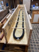
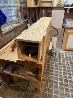
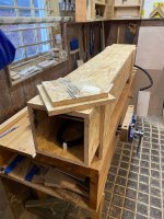
I did get round to making a steam box. Nothing too interesting about it really - it's OSB and pocket hole screw construction. Pocket hole was the way to go because I found it impossible to screw into the 'end grain' of OSB. I glued most of the seams with PU glue, but, currently, I've left the top unglued in case I need to get inside to make any changes.

IMG_2805.jpeg

IMG_2807.jpeg

IMG_2808.jpeg

The steam is supplied by a wallpaper stripper with holes punched in the hose.

I've had a bit of a play with it and it seems to work OK. I'm not sure OSB was the best material to use as it swells quite a lot. It hasn't fallen apart yet though!
 
I've seen the hack with the dowels supporting the workpiece for all round steaming, but I haven't seen the perforated hose inside before. Nice.

I've also seen them slightly tilted to drain away condensate through a hole into a hose into a container.
 
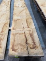
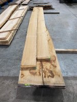
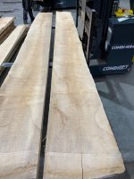
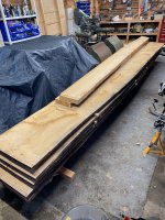
I also took the plunge, sold all three of my kidneys, robbed a bank and bought the wood. In seriousness, although the wood was very expensive, I unexpectedly got a part time temporary job which is paying for it.

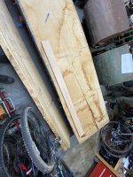
I got the wood from English Woodland Timber. Im sure many of you who live in the South will have been there, but it was my first trip and I was impressed. A very helpful member of staff helped me find what I needed - moving piles of boards and getting stuff down from high shelves before sorting through them for me. He alsio gave me a tour of the whole site which was interesting.

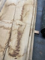
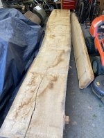
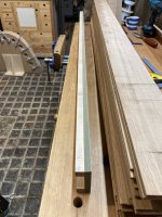
I bought 5 very wide (c. 600mm) and very long (5m) 27mm thick French oak boards from a single tree. I'll use that to make the laminations for the legs.

I also bought two thicker oak boards which will make the long and lateral rails for the table's support structure.

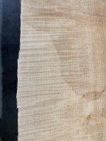
Finally, I bought a couple of boards of sycamore for the top. The sycamore has a nice ripple in it which I'm hoping will look good.

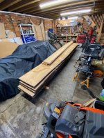
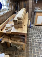
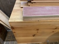
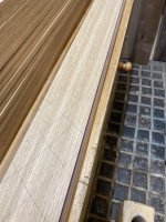
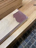
Here are some photos from the timber yard and of the wood piled in my (now very cramped for space) garage.

IMG_2816.jpeg

IMG_2817.jpeg

IMG_2818.jpeg

IMG_2819.jpeg

IMG_2830.jpeg

IMG_2831.jpeg

I'm going away for a couple of weeks soon, so probably won't be able to do any more on this for a little while.
 
Malc2098":1d8sov0y said:
I've seen the hack with the dowels supporting the workpiece for all round steaming, but I haven't seen the perforated hose inside before. Nice.

I've also seen them slightly tilted to drain away condensate through a hole into a hose into a container.

I have got a drain hole at either end so that I can tilt it one way or the other to let the drips out. I think I'll do it outside if I can to avoid too much condensation in my workshop, so the drips can just go on the ground.

When I steam the thin laminations, my plan is to make 'combs' which will hold them apart so that the steam can get to all surfaces at once.
 
Wow, that rippled Sycamore is beautiful.

I made the last two ukuleles with some that came from a tree felled in Kent, and it looks so good, I bought some more for the next two.
 
NickM":1gckwos1 said:
wood piled in my (now very cramped for space) garage.

Wow, you call that cramped?! After tidying my garage as much as possible I have about half that amount of space :lol:

That sycamore looks lovely.
 
That all looks very promising and congratulations on becoming another of their helpful staff. I hope you qualified for a staff discount!
 
I’ve never see a steam box with a perforated hose before, all well and good but not sure, is it necessary or not? Did you drill larger holes the further away from the start? As in gradually increasing the size of hole?
Good idea using the suspension dowels.
Ian
 
Cabinetman":58va6ikt said:
I’ve never see a steam box with a perforated hose before, all well and good but not sure, is it necessary or not? Did you drill larger holes the further away from the start? As in gradually increasing the size of hole?
Good idea using the suspension dowels.
Ian

I just punched the holes with an awl. I do wonder if they need to be bigger, but it looked as though a nice lot of steam was coming out of all of the holes.
 
I've been working hard on this project so it's high time I did an update.

I've started with the laminated legs. There are 8 curved legs to make (four in two pedestals). Each leg has 22 tapered laminations.

The process for making the laminations was:

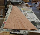
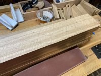
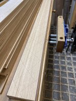
Lay out the blanks on the timbers. To help with this, I made a template. It was a case of avoiding the worst knots, splits and sap wood, and trying to keep the grain as straight as possible. I managed to get 15 or 16 blanks out of each board. Each blank produces three laminations - i.e. 45-48 per board, which is enough for two legs.

IMG_2940.jpeg

IMG_2941.jpeg

IMG_2942.jpeg

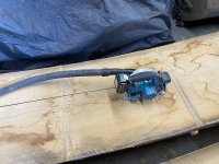
Next, I roughly cut the board up using a circular saw to get it into more manageable pieces.

IMG_2943.jpeg

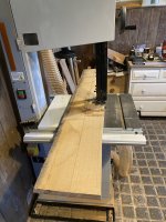
I then used the band saw to cut them close to final width.

IMG_2944.jpeg

I ended up with a nice stack of blanks.IMG_2945.jpeg
 
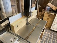
The blanks were then planed on one face and edge (no photos of this, but it was done by machine) so they could be resawn on the bandsaw. I aimed for approximately 6mm thicknesses of the bandsaw. I made a fence for the bandsaw which helped.


IMG_2946.jpeg

After each cut, I re-planed the face of the blank. I then put each lamination through the thicknesser just to get them all even thickness before tackling the tapering.

IMG_2947.jpeg

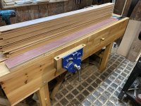
For the tapering, I made the 'sled' shown in the above photo. It's an MDF top with ply 'runners'. The runners have the taper in them and were hand planed to size. The taper is quite subtle - 2mm to 3.5mm over the length of the leg (although the sled was longer). I stuck sandpaper to it to prevent the laminations slipping.IMG_2948.jpeg

IMG_2949.jpeg
 
I did most of the tapering using the thicknesser as it's much faster than the drum sander.

These photos show the taper progressing:


IMG_2951.jpeg

IMG_2952.jpeg

IMG_2953.jpeg

The downside of the thicknesser is that you're never far from disaster when using such thin wood:

IMG_2956.jpeg

However, even these were usable because I'd given myself plenty of extra length to deal with this sort of issue as well as snipe etc.

Final dimensioning was done with a drum sander. That also leaves a better finish, free of planer ridges. I didn't take any photos of that.

As you'll have seen, this was a very dull process. Hours of pushing wood through machines. It wasn't much fun, but that's what I signed up for with this leg design.
 
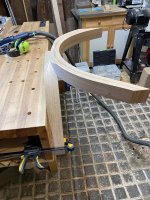
The legs were glued up using the former I've show previously. As noted in the posts above, I was worried whether I could clamp them up without getting gaps, and had settled on having to steam them first. However, as it turned out, I didn't need to do that. I think the difference was that on my test piece I hadn't sanded the laminations and, as a result, the layers were 'snagging' on each other because of the planer ridges. With smoother surfaces, they slid past one another and clamped up nicely.

However, the steamer did help me make a thicker (c.12mm) oak clamping caul which prevented the clamps producing an uneven surface.

IMG_2924.jpeg

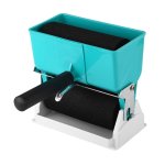
The glue I used was a resin/powder urea formaldehyde which has a long open time and is ideal for veneering/laminating. I didn't take photos of the gluing process, but I used one of these roller/hopper things which made it very quick and easy.

image.jpeg

The 'proper' Pfohl versions cost a fortune, but mine cost about £20. I had to fettle it a tiny bit, but it worked well enough.
 
I didn't take photos of the cleaning up process. The glue squeeze out is like glass and is quite hard to remove. My process was to chisel and scrap off the worst before planing flat and square. I then had around 10mm of extra thickness to remove and did that by hand sawing off most of the waste before planing flat.

Whilst the legs were still square (they later get tapered in the other dimension), I cut them to length. I did that using a full size drawing. The aim was to get the bottom surface of the foot, and the top (under table) surface parallel to each other. I used the first leg as a template for the rest.

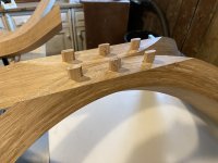
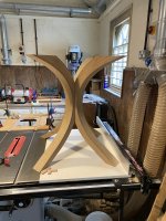
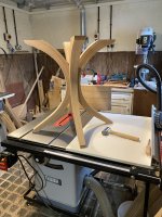
The next job was to make the joints. These are essentially a ninety degree angle cut into the leg. Each leg can then join in the centre.

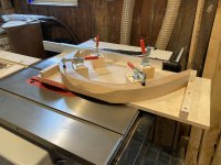
I removed the bulk of the waste on my table saw, using a jig I made to hold the leg. (Guard removed for photo...)

IMG_2965.jpeg

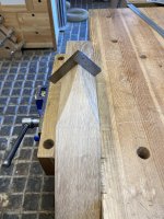
The faces were then planed by hand and checked for square.

IMG_2990.jpeg
 
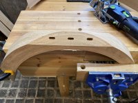
The joints have dominos for alignment and sheer strength.

IMG_2968.jpeg


IMG_2969.jpeg

IMG_2970.jpeg

IMG_2971.jpeg

I think the joints will need a bit of fettling to get them really good (I also need to make some shaped clamping cauls so that I can clamp them up really tight), but I'm going to do that later, not least because things could move around a bit.
 
The legs are looking rather 'chunky' so the next step was to taper them in the other dimension.

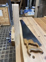
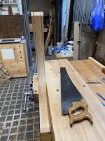
I hand sawed the bulk of the waste off and then planed them. It was a lot of sawing, but with a freshly sharpened rip saw it wasn't as bad as I feared.

IMG_2992.jpeg

IMG_2993.jpeg

They're now looking a bit more svelte. The inside faces are going to be rounded which will add more elegance I hope.

IMG_2995.jpeg

All 8 legs are currently at this stage.
 
Back
Top