• Hi all and welcome to TheWoodHaven2 brought into the 21st Century, kicking and screaming! We all have Alasdair to thank for the vast bulk of the heavy lifting to get us here, no more so than me because he's taken away a huge burden of responsibility from my shoulders and brought us to this new shiny home, with all your previous content (hopefully) still intact! Please peruse and feed back. There is still plenty to do, like changing the colour scheme, adding the banner graphic, tweaking the odd setting here and there so I have added a new thread in the 'Technical Issues, Bugs and Feature Requests' forum for you to add any issues you find, any missing settings or just anything you'd like to see added/removed from the feature set that Xenforo offers. We will get to everything over the coming weeks so please be patient, but add anything at all to the thread I mention above and we promise to get to them over the next few days/weeks/months. In the meantime, please enjoy!

Marking Gauge Attempt

Dr.Al

Old Oak
Joined
Dec 31, 2020
Messages
3,884
Reaction score
2,803
Location
Dursley, Gloucestershire
Name
Al
After seeing Mike's beautiful marking gauges, I thought it might be an interesting little project to have a go at. I thought I'd post a WIP so that you can see all the mistakes I make along the way.

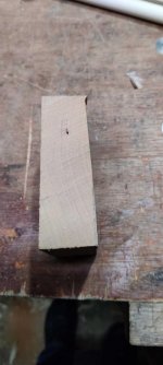
I started with this pile of bits: a lump of cherry, a lump of beech and a length of 16 mm beech dowel:

IMG_20220220_112031 - Copy.jpg

The first job was to hack the bit of cherry down to size a bit using my portable workbench and ryoba:

IMG_20220220_112307 - Copy.jpg

Then I marked it out at 32 mm, thinking I'd saw it off wide of that line and stand a fighting chance of getting a 30 mm ish thick piece out of it:

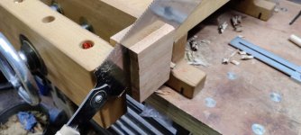
IMG_20220220_112428 - Copy.jpg

IMG_20220220_112645 - Copy.jpg

Must try harder:

IMG_20220220_112801 - Copy.jpg

At least I'd left plenty of extra material on there! Next was a quick attack with a #4 to get it as close to parallel as my skills allow (which is to say, not very parallel!)
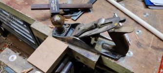
IMG_20220220_113208 - Copy.jpg

With that done, I could mark out a 60 mm diameter circle to give the shape that will form the body of the marking gauge (I'll flatten one side at some point so it doesn't roll of the bench, but that's a job for much further down the line).
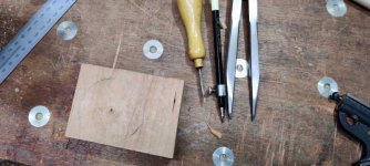
IMG_20220220_113537 - Copy.jpg

I then used the compasses in pointy stick mode to mark a second hole location 18 mm from the centre:

IMG_20220220_113703 - Copy.jpg

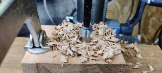
I'd planned at this point to try out my recently-acquired second-hand brace, but it turns out that the bits I have start at 6 mm and go up in 3 mm increments, so I don't have one that's 16 mm to match the dowel. Unlike Mike, I don't have a friend with a wood lathe, so I'd rather stick to the size of the dowel. I do have a 16 mm Forstner bit and I guess I could have tried putting that in the brace, but not having used the brace before I thought I'd start with a auger bit when I used that and so I went over to the pillar drill instead (I'm not sure the C-clamp is really necessary for a hole like this, but I figured it was better safe than sorry):

IMG_20220220_113912 - Copy.jpg

IMG_20220220_113947 - Copy.jpg

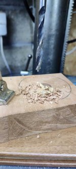
I then drilled out the offset hole, starting with a 6 mm wood drill and then following with a 6.3 mm HSS drill:
IMG_20220220_114542 - Copy.jpg

IMG_20220220_114610 - Copy.jpg

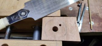
Now it was time to hack the bit of cherry down to somewhere near final size. For that it was back to the portable workbench and ryoba:
IMG_20220220_114748 - Copy.jpg

IMG_20220220_114939 - Copy.jpg

I really didn't expect this to work given the lack of contact area right over at one end of the vice, but it was quicker than any other method I could think of and it worked absolutely fine:

IMG_20220220_115013 - Copy.jpg

IMG_20220220_115235 - Copy.jpg

With that done, I stuck it back in the portable workbench vice and attacked with the fine side of my rasp:

IMG_20220220_115503 - Copy.jpg

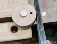
When it was getting close to size, I put a small length of dowel in the vice and rotated the cherry block with my left hand while rasping it with my right:
IMG_20220220_120332 - Copy.jpg

I used one of the bench dog hole fillers from my bench with a screw fitted to it to draw a 20 mm diameter circle centred on the offset hole. With hindsight I probably could have done this more easily before drilling the hole out, but this worked fine:

IMG_20220220_121227 - Copy.jpg

I then drew some lines tangential to the newly drawn circle at an angle that looked about right by eye, transferred the lines round the edge and marked a couple of joining lines 10 mm apart in the middle of the stock:

IMG_20220220_121456 - Copy.jpg

More to follow....
 
I hope you don't mind me mentioning this, but looking at where you marked the whole circle, saying that you'd cut a flat later, I couldn't help thinking that you could have just moved the centre over a bit and used some of the flat side you already had...

That aside, thanks for writing this up. There are so many different ways to make marking gauges and I look forward to seeing how these will work. Something ingenious, I'm sure.
 
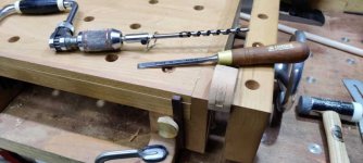
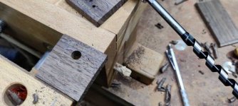
Next I decided to be brave and try the brace as I have a 9 mm bit. I used a 10 mm chisel to make a flat surface on the edge (probably unnecessary, but I figured it couldn't hurt) and lined up one of the lines I'd drawn on the face with the vice jaws:

IMG_20220220_122238 - Copy.jpg

Nothing for it but to have a go:

IMG_20220220_122305 - Copy.jpg

That worked really well, so I did the same for the other end of the hole:

IMG_20220220_122551 - Copy.jpg

and one more time resulting in this:

IMG_20220220_122722 - Copy.jpg

Next up was a 10 mm chisel (and a small pair of pliers to for easy waste removal) to shape the hole properly:

IMG_20220220_123158 - Copy.jpg

As I got near the bottom of the hole, I turned the block round and put a piece of dowel in the hole to limit break-out:

IMG_20220220_123643 - Copy.jpg

The next challenge (which - spoiler alert - didn't go well!) was to make the cam.

I started with this offcut of American black walnut, which I cut a quarter off:

IMG_20220220_124101 - Copy.jpg

I then tried to plane it to a nice consistent 10 mm thickness. Thankfully, there were four quarters as I was relatively successful on my third go :oops:

IMG_20220220_125150 - Copy.jpg

I then used the same bench dog hole filler thing to mark out a 20 mm circle:

IMG_20220220_125350 - Copy.jpg

I then drew a handle shape sort of thing, trying to follow the grain direction as that seemed like a good idea:

IMG_20220220_125623 - Copy.jpg

I thought I'd try the brace again, firstly to make the shape in the nook between the handle and the circular bit. I drilled most of the way through (until I could feel the point appearing at the back), then turned it over and drilled from the back, using what I thought was the hole from the previous drilling. Unfortunately I somehow picked the wrong dot and ruined the part:

IMG_20220220_125852 - Copy.jpg

Remember how I said that this was the third of four quarters? This is the fourth:

IMG_20220220_130204 - Copy.jpg

After drilling the hole to form the outer shape, I drilled the centre hole, starting with a 6 mm wood bit and then finishing with a 6.4 mm HSS drill:

IMG_20220220_130415 - Copy.jpg

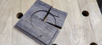
I then started cutting round the profile. I thought I'd rough it out first with the ryoba and then figure out how to shape it properly afterwards. As soon as the saw started cutting, this happened (which I guess I should have seen coming):

IMG_20220220_130529 - Copy.jpg

At that point, I decided it was time for lunch and a rethink. I'm not sure what I'll do now, possibly try a different wood (e.g. the beech slab I showed in the first photo) or I could go for the "safe" option and make it out of brass or aluminium (although that might risk damaging the dowel). :eusa-think:
 
AndyT":sdbi6sq1 said:
I hope you don't mind me mentioning this, but looking at where you marked the whole circle, saying that you'd cut a flat later, I couldn't help thinking that you could have just moved the centre over a bit and used some of the flat side you already had...
That's a good point, thanks for mentioning that. None of the sides were especially flat to be honest, so it still would have needed tidying up. Also, I hadn't worked out where the flat should be relatively to the cam slot, so I figured it was easier to think about that later. Mostly though, I didn't think of that idea :lol: I'll try to remember that one for next time!
 
RogerS":2pmo2h8b said:
Lurker":2pmo2h8b said:
Can you give me a link to the metal thingy in picture 3, please.

It's this one, Jim.

https://www.axminstertools.com/axminste ... are-900043

They are bloody brilliant. I have 4....ideal for setting and marking out tenons and mortices.

They look pretty good. I assume that by using this type of thingy, you don't need to use a pencil gauge (which I've never found entirely satisfactory)?

I suppose it could also be used with my new hybrid gel pen that Alf recommended? - Rob
 
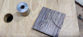
After lunch, a crossword and a ponder, I decided to have a go at a brass cam. I can always think about replacing it with a wooden one later and the brass one will be a good and easy way of proving the principle.

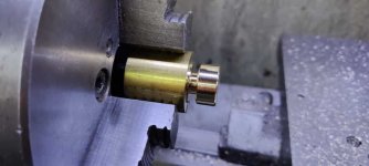
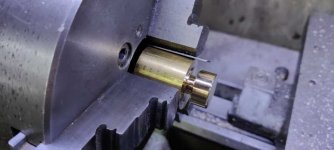
Off I went to the lathe and chucked up an offcut of brass bar:

IMG_20220220_152832 - Copy.jpg

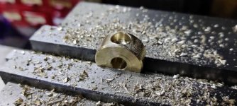
A minute or so later, it looked like this:

IMG_20220220_153356 - Copy.jpg

I then grabbed a bit of 0.8 mm feeler gauge stock out of the drawer in which I keep such things (I've got lots of this as I bought two cheap sets when I got my first lathe and used the feeler gauge stock to lift tools up to centre height). Putting the feeler gauge stock next to one of the chuck jaws makes the part turn eccentrically:

IMG_20220220_153456 - Copy.jpg

I then drilled a hole...

IMG_20220220_153612 - Copy.jpg

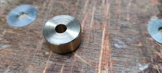
... parted it off and then tidied up the burrs:

IMG_20220220_154110 - Copy.jpg

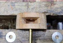
With a bit of brass bar shoved in the hole in the marking gauge's body, I could do some experimentation. The first thing this showed was that I needed to open up the bottom of the hole a lot more:

IMG_20220220_155143 - Copy.jpg

I then mounted the cam on the outside for a quick test and to help me work out where to put the arm:

IMG_20220220_155457 - Copy.jpg

With that marked up, it was off to the mill to drill an 8 mm hole:

IMG_20220220_160212 - Copy.jpg

A bit of 8 mm bar was tidied up on the lathe and then I turned to ol' faithful to fix it in place:

IMG_20220220_161103 - Copy.jpg

While that was drying, I cut off a bit of the long bar I was using as a hinge pin and faced it to length:

IMG_20220220_161559 - Copy.jpg

Then I could assemble everything and try it out. When the bar looks like this, the dowel can slide freely back and forth:

IMG_20220220_162153 - Copy.jpg

Move it to here and the dowel is locked solid:

IMG_20220220_162148 - Copy.jpg

That brings us up to date again. It's not going to win any beauty contests (especially not any that Mike G has entered with his gauges!), but I'm pleased with how it has gone so far. I've still got to add a bit more finesse to the body shape and make some sort of cutting implement (I haven't decided what type yet, although I'm leaning towards a knife style one with a wedge) to go through the dowel, but it's not a bad start.

Two things I've realised with the benefit of hindsight:

1. I don't need a flat on the side of the gauge as the cam lever thing will stop it rolling away

2. It would have been better to mark up a 21 (ish) mm wide vertical mortice, rather than having the sides of the mortice tapering out. The amount of movement needed to make the cam work is fairly small and the hole would have been much neater (and probably the right size on the first attempt).

Still, live and learn an' all that...
 
Brill DrAl, I was wondering how you were going to make it eccentric, simple enough I suppose. So did you glue the two bits of brass together? I only ask as I have a Chinese door plate lock thingy coming up soon, I suppose it has to be a good fit to start with bit like wood really! Ian
 
Cabinetman":3bdjyhfn said:
Brill DrAl, I was wondering how you were going to make it eccentric, simple enough I suppose. So did you glue the two bits of brass together? I only ask as I have a Chinese door plate lock thingy coming up soon, I suppose it has to be a good fit to start with bit like wood really! Ian

Thanks Ian. Yes, two of the bits of brass (the cam and the handle) are glued together with Loctite 603, which is my go-to glue for metal-to-metal stuff. I've had that bottle for about 10 years now and it's still going strong. A little goes a long way.
 
That's a slightly different arrangement than my old ones, here:

LUE2hPA.png

The thing that worries me a little about brass is that it is a relatively slippery thing, and you are going to want enough friction in the system such that the setting survives being repeatedly picked up and put down. It's also relatively harder than the wood of the shaft, so has the chance of leaving crush marks. noetheless, it is an interesting experiment. Ultimately, my lever ones didn't provide enough friction, and would lose the setting too often. I hope your works better.
 
These are the ones I make usually from maple with rosewood or box wedges.

Marking gauges by Pete Maddex, on Flickr

In the past I made some copies of the Stanley ones.

DSCF0012 by pete maddex, on Flickr

These are the parts needed.

DSCF0015 by pete maddex, on Flickr

the Stanley copies are tricky to get the mortice square to the head, so after finding a wedge one I copied that.

I have given a few of mine away as secrete Santa gifts and they seem to like them.

Pete
 
I've gone all Japanese:

IMG_6526.jpeg

Only one of those is an original from Japan via CHT and is no longer available. Oak with HSS cutters from old hacksaw blades. A red line scored across the end of the stem indicates the point of the cutter. Also I have a slightly bigger version as a panel gauge:

IMG_6527.jpeg

Oak stock with a holly stem and very carefully ground masonry nail for the cutter - Rob
 
Mike G":39zxw05q said:
That's a slightly different arrangement than my old ones, here:

LUE2hPA.png

The thing that worries me a little about brass is that it is a relatively slippery thing, and you are going to want enough friction in the system such that the setting survives being repeatedly picked up and put down. It's also relatively harder than the wood of the shaft, so has the chance of leaving crush marks. noetheless, it is an interesting experiment. Ultimately, my lever ones didn't provide enough friction, and would lose the setting too often. I hope your works better.

I was a bit concerned about the crush marks (hence originally starting with a wooden cam). I'll see what it looks like and whether it bothers me. I'm sure I'll have a go at an alternative design in due course: it was mostly an excuse to get out to the workshop and do something relatively quick. With the brass cam it certainly seems to lock rigidly, but then I haven't used it in anger yet. Given the length of 16 mm beech dowel I've got, one option for the crush marks might be just to make several shafts and not to be too precious about them.

I'd definitely like to have another go at a wooden cam, but it needs a different design approach. I've had a few ideas, so I'll keep playing.

Having seen all the other home-made marking gauges that have been posted on this thread and the other one though, I'm feeling very ashamed of the aesthetics of my efforts :(
 
Dr.Al":fapkblwf said:
......Having seen all the other home-made marking gauges that have been posted on this thread and the other one though, I'm feeling very ashamed of the aesthetics of my efforts :(

Don't be. It's a tool.
 
Back
Top