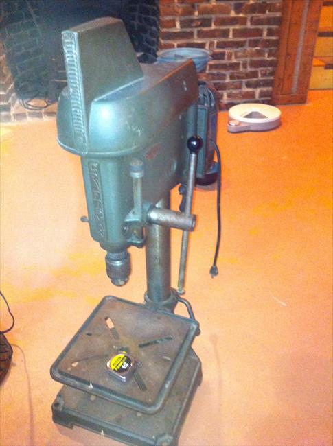
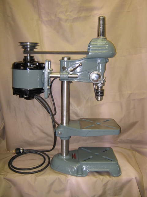
• Hi all and welcome to TheWoodHaven2 brought into the 21st Century, kicking and screaming! We all have Alasdair to thank for the vast bulk of the heavy lifting to get us here, no more so than me because he's taken away a huge burden of responsibility from my shoulders and brought us to this new shiny home, with all your previous content (hopefully) still intact! Please peruse and feed back. There is still plenty to do, like changing the colour scheme, adding the banner graphic, tweaking the odd setting here and there so I have added a new thread in the 'Technical Issues, Bugs and Feature Requests' forum for you to add any issues you find, any missing settings or just anything you'd like to see added/removed from the feature set that Xenforo offers. We will get to everything over the coming weeks so please be patient, but add anything at all to the thread I mention above and we promise to get to them over the next few days/weeks/months. In the meantime, please enjoy!

New old drill

Wizard9999

Old Oak
Joined
Aug 8, 2014
Messages
1,409
Reaction score
0
Location
Eversley, Hampshire
A week or so ago I picked up an eBay purchase. Now the workshop has been tidied up after I finished the ducting I have finally taken it out of the car.
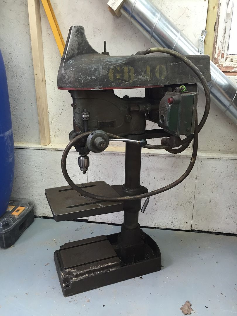
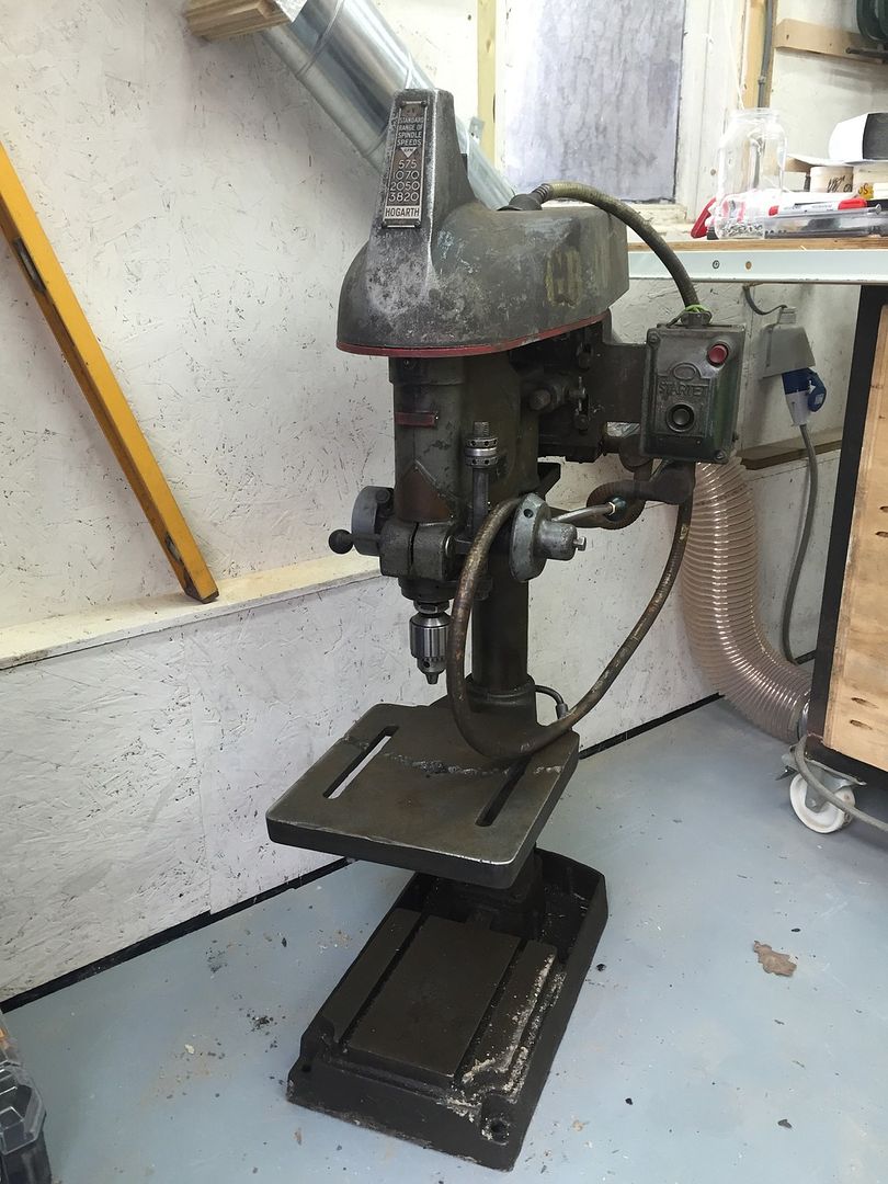
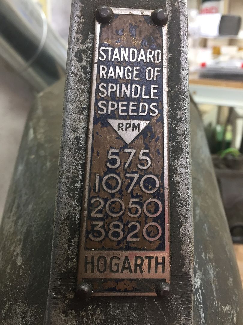
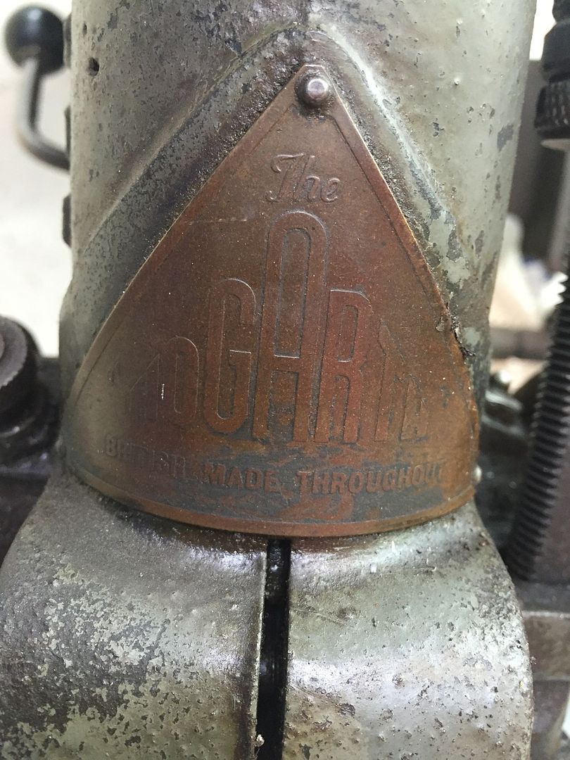
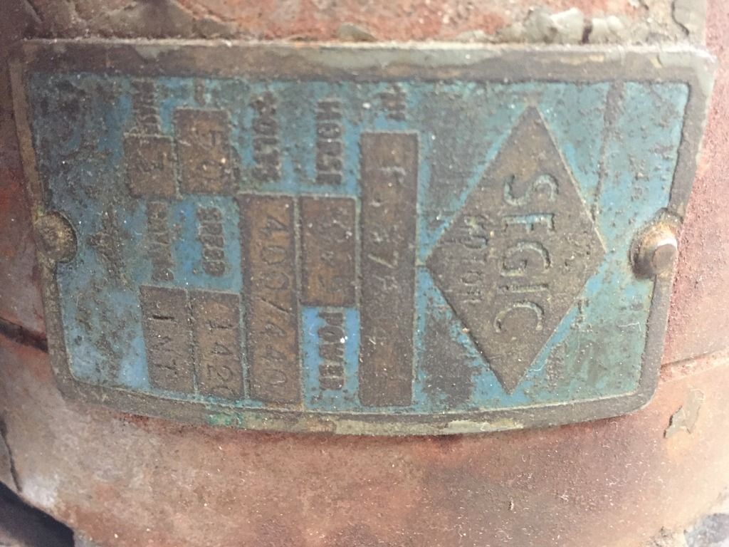


It was a bit of a punt but the price was considerably lower than a Fobco or Meddings. It came from a small engineering workshop that two guys who work in automotive ran in their spare time and now having had a much better look at it has clearly been used until very recently and I have so far been been unable to find any rust, a lot of grime but no rust.

I have been unable to find any real info about Hogarth as a brand of drill. I found one website about lathes that suggested Hogarth lathes were most likely imported to the UK, but as per the picture above the badge on the drill claims it is "British made throughout". I also find the letters / numbers stencilled on the side, which look vaguely military to me. Any information anyone has on Hogarth would be much appreciated.

It is 3 phase so I will need some assistance from Bob before I can use it! From the plate on the motor I believe it only runs of 400/440v, so if I understand correctly it will need not just an inverter but one that also steps up the voltage.

Terry.
 
That looks so much like military stenciling on the side. Just what you might see on an old army Landrover. Buy yourself a can of cheap red paint from a car shop and just spray the whole thing, moving parts and all. It'll look a million dollars........


Well, that's how people normally restore old machinery, isn't it? :eusa-whistle: :lol:
 
Mike G":39ktj5nn said:
That looks so much like military stenciling on the side. Just what you might see on an old army Landrover. Buy yourself a can of cheap red paint from a car shop and just spray the whole thing, moving parts and all. It'll look a million dollars........


Well, that's how people normally restore old machinery, isn't it? :eusa-whistle: :lol:

Hey now! When I do a rattle-can resto, I specifically try to mask off the moving parts. Well, most of them anyway...:)

Kirk
who actually has a rattle-can restoration going on in his garage right now, pictures later...
 
Well that looks like a very useful tool. You appear to be missing a couple of the handles for advancing the quill, but they are not difficult to replace. Should do you for lots of years. [emoji2]
 
Terry - yes I noticed this in the background in one of your extraction photos - very solid looking old beast .
Re the strange horn-shaped extrusion/protrusion on the top front part , is there anything inside that ?

Steve
 
tracerman":1e541ys8 said:
Re the strange horn-shaped extrusion/protrusion on the top front part , is there anything inside that

The kids love that, they think it looks like some sort of alien :lol:. As far as I can see it is a really 'interesting' stylistic choice.

Terry.
 
Andyp":36i8i51f said:
Nice one Terry. I love the nice arc pattern in the table. :D


Ah yes the dreaded "arc of shame".....

Looks a good solid machine. The top to bottom dimension of the head should give good quill travel and rigidity - just compare with modern offerings!

Bargain price too!

I think there are two options on the motor Terry. Either I can modify you an inverter to give 240-400 conversion as well as 3 phase or there might be the possibility of modifying the motor to delta connection and use a standard 240 in - 240 out inverter.
I could do the latter if you dropped the motor off sometime whilst you are refurbishing the rest of the machine?

Either way the inverter would be of suitable size (and function) to replace the NVR and mount in the same place or maybe on the other side according to taste.

I can't quite read the motor plate power figure. Is it 0.5hp?

HTH

Bob
 
The worst thing about these old drills ( especially on my Meddings) is the table adjustment - mines very heavy and now way can you carry out any fine adjustment with it.
I generally bash the locking lever with a piece of wood and hold onto the table with my other hand hoping I won't let go! [emoji3]


Rod
 
9fingers":2hsbnl3e said:
Andyp":2hsbnl3e said:
Nice one Terry. I love the nice arc pattern in the table. :D


Ah yes the dreaded "arc of shame".....

Indeed, not pretty, but so far I can't see that this is consistent with any other mistreatment of the machine, which is good.

9fingers":2hsbnl3e said:
Looks a good solid machine. The top to bottom dimension of the head should give good quill travel and rigidity - just compare with modern offerings!

Bargain price too!

Yes, I have been uncharacteristically patient and watched a lot of drills and bid on a few but usually they went above what I wanted to pay, I guess because nobody seems to know anything about Hogarth it didn't attract the interest or bids that others I have followed did.

9fingers":2hsbnl3e said:
I think there are two options on the motor Terry. Either I can modify you an inverter to give 240-400 conversion as well as 3 phase or there might be the possibility of modifying the motor to delta connection and use a standard 240 in - 240 out inverter.
I could do the latter if you dropped the motor off sometime whilst you are refurbishing the rest of the machine?

Either way the inverter would be of suitable size (and function) to replace the NVR and mount in the same place or maybe on the other side according to taste.

I can't quite read the motor plate power figure. Is it 0.5hp?

HTH

Yes, very helpful Bob, thanks. Taking the last point first, it is hard to read even in the flesh but I believe it does say 0.5hp on the motor plate.

At the moment to be honest I am not planning on much restoration, the machine appears in very good working order. I could strip it down to paint it, etc. but to be honest I am not inclined to do so for two reasons. First, there appears no need to from a mechanical perspective and second, it is an old drill and I see no shame in it showing its age. I will look to replace the missing handles, but apart from that I think it will just get a good clean to remove grime and a lot of metal shavings still collected by that grime.

In terms of three phase to single phase I guess there are two things in my mind, what is the best answer and some element of practicality. Is either of the options you suggest a lot better as a technical answer than the other? For both of the options, if I bring the motor down is the fitting of the inverter something that can be done at that time, i.e. does one or both of them mean a trip to drop off and then a trip on another occassion to pick up?

Thanks,
Terry.
 
Terry , just an over-optimistic thought , if the pillar is same as another more modern drill , maybe you could acquire the toothed collared winding handle gizmo for your table adjustment scenario . ? . Well I did say over-optimistic didn't I . Carry on .

Steve
 
tracerman":1yt9uvcn said:
Terry , just an over-optimistic thought , if the pillar is same as another more modern drill , maybe you could acquire the toothed collared winding handle gizmo for your table adjustment scenario . ? . Well I did say over-optimistic didn't I . Carry on .

Steve

That is a very good idea I had not tought of Steve, a bit of measuring called for I think.

Thanks,
Terry.
 
Wizard9999":2bspdk1w said:
Yes, very helpful Bob, thanks. Taking the last point first, it is hard to read even in the flesh but I believe it does say 0.5hp on the motor plate.


In terms of three phase to single phase I guess there are two things in my mind, what is the best answer and some element of practicality. Is either of the options you suggest a lot better as a technical answer than the other? For both of the options, if I bring the motor down is the fitting of the inverter something that can be done at that time, i.e. does one or both of them mean a trip to drop off and then a trip on another occasion to pick up?

Thanks,
Terry.

To be honest once completed either solution will work just as well as the other.
One involves modifying the inverter and the other involves modifying the motor.

The latter can sometime be impractical if the insulation inside the motor is old and fragile and moving the wires causes cracks. That can only be judged once opened up.

As for number of trips, the motor is not a while you wait job and would need to come here to be done as I have the facilities here to sort out any problems if they arise.

Fitting a modified inverter should be something you can do yourself if you wanted to and involve no visits. The inverter is couriers to you, you wire it up, job done.

Whichever route you decide on, there is a second level of choice.

One is to use the keypad controls on the inverter to turn it on and off and to change speed with up and down arrow buttons or
two,to have a separate control box with big chunky buttons and a rotary knob for speed.
This second option also allows you to fit an emergency stop kick switch if you so desire which cannot be combined with option 1.

All options will provide a display with an indication of the speed it will start at from the off position. So in terms of mounting the inverter, you need to be able to see the display and to reach the keypad in option one or just to see the display in option two, with the buttons on a separate panel that is within reach.

Sometimes people are attached to the look and feel of the original NVR and usually it is possible to re-use those stop and start buttons to control the inverter and also fit the speed control knob on the same box.

Within reason, you can have what you want.

For info typical inverter for your job is 75mm wide, 175 tall and 175 deep.
Almost certain to be a Siemens Micromaster 440 case style A (the smallest one in the range) - you can google/ebay for pictures.
Prices vary according to how cheaply I can buy them in and how much work is needed for the controls.
I can also replace motor bearings if needed should you go down the motor modification route.
Full 12month warranty on all work and inverters. Repair or replace at my option.
Tech support offered for as long as I'm able to do it!

Bob
 
tracerman":16ms5szg said:
Terry - yes I noticed this in the background in one of your extraction photos - very solid looking old beast .
Re the strange horn-shaped extrusion/protrusion on the top front part , is there anything inside that ?

Steve

Steve:

The horn covers the top of the spindle when it's fully retracted. Here's a different example, on a Craftsman DP from the 1940's:

13607-A.jpg


And on this Atlas there is just a cover, but the relationship is pretty clear:
17406-B.jpg


Kirk
 
Sorry for delay coming back to you, was getting some info first.

9fingers":25hhdyyu said:
To be honest once completed either solution will work just as well as the other.
One involves modifying the inverter and the other involves modifying the motor.

The latter can sometime be impractical if the insulation inside the motor is old and fragile and moving the wires causes cracks. That can only be judged once opened up.

Well it has been suggested to me that the drill dates from between 1935 and 1950, not sure if the motor will have been replaced since then but my guess is it may not respond well to being modified and that may just open up a whole can of worms.

9fingers":25hhdyyu said:
As for number of trips, the motor is not a while you wait job and would need to come here to be done as I have the facilities here to sort out any problems if they arise.

Fitting a modified inverter should be something you can do yourself if you wanted to and involve no visits. The inverter is couriers to you, you wire it up, job done.

My son's annual cub camp is usually near you, so I held off on a fonal decision until I knew the venue as I thought maybe I could drop off to you when I take him and collect when I pick him up. Of course this year it is nowhere near you, typical!

All in all I therefore think the inverter modified to deal with the motor needing 400/440V is the way to go, rather than modifying the motor. Though as you can guess, I'll be worrying about the fitting!

9fingers":25hhdyyu said:
Whichever route you decide on, there is a second level of choice.

One is to use the keypad controls on the inverter to turn it on and off and to change speed with up and down arrow buttons or
two,to have a separate control box with big chunky buttons and a rotary knob for speed.
This second option also allows you to fit an emergency stop kick switch if you so desire which cannot be combined with option 1.

All options will provide a display with an indication of the speed it will start at from the off position. So in terms of mounting the inverter, you need to be able to see the display and to reach the keypad in option one or just to see the display in option two, with the buttons on a separate panel that is within reach.

Sometimes people are attached to the look and feel of the original NVR and usually it is possible to re-use those stop and start buttons to control the inverter and also fit the speed control knob on the same box.

Within reason, you can have what you want.

For info typical inverter for your job is 75mm wide, 175 tall and 175 deep.
Almost certain to be a Siemens Micromaster 440 case style A (the smallest one in the range) - you can google/ebay for pictures.
Prices vary according to how cheaply I can buy them in and how much work is needed for the controls.
I can also replace motor bearings if needed should you go down the motor modification route.
Full 12month warranty on all work and inverters. Repair or replace at my option.
Tech support offered for as long as I'm able to do it!

Bob

On second level choices I think I will be happy to simply use the inverter for on and off and speed changes. I suspect that I will not be playing with the speed every time I use the drill, so the benefit of the rotary knob may be wasted on me.

The current switch is 145mm high, by 100mm wide, by 85mm deep so the inverter will be a touch narrower, a bit taller with the biggest difference being the inverter will be a lot deeper (which won't affect fitting it). Therefore I think it should work well to remove the current switch and mount the inverter on the same 'plate' the switch is being taken off from, even if the holes are in the wrong place I can mount a piece of plywood to the 'plate' and then mount the inverter to the plywood. Does that make sense?

Assuming that is all the info / choices, do you need anything more from me to kick the process off?

Thanks,
Terry.
 
kirkpoore1":2bh4khkc said:
tracerman":2bh4khkc said:
Terry - yes I noticed this in the background in one of your extraction photos - very solid looking old beast .
Re the strange horn-shaped extrusion/protrusion on the top front part , is there anything inside that ?

Steve

Steve:

The horn covers the top of the spindle when it's fully retracted. Here's a different example, on a Craftsman DP from the 1940's:

Having been out and taken a look of course Kirk is completely correct :oops: . But I'm still telling my kids it is because it is an alien drill :lol: .

Terry.
 
Wizard9999":3ex1pc0b said:
Sorry for delay coming back to you, was getting some info first.

9fingers":3ex1pc0b said:
To be honest once completed either solution will work just as well as the other.
One involves modifying the inverter and the other involves modifying the motor.

The latter can sometime be impractical if the insulation inside the motor is old and fragile and moving the wires causes cracks. That can only be judged once opened up.

Well it has been suggested to me that the drill dates from between 1935 and 1950, not sure if the motor will have been replaced since then but my guess is it may not respond well to being modified and that may just open up a whole can of worms.

9fingers":3ex1pc0b said:
As for number of trips, the motor is not a while you wait job and would need to come here to be done as I have the facilities here to sort out any problems if they arise.

Fitting a modified inverter should be something you can do yourself if you wanted to and involve no visits. The inverter is couriers to you, you wire it up, job done.

My son's annual cub camp is usually near you, so I held off on a fonal decision until I knew the venue as I thought maybe I could drop off to you when I take him and collect when I pick him up. Of course this year it is nowhere near you, typical!

All in all I therefore think the inverter modified to deal with the motor needing 400/440V is the way to go, rather than modifying the motor. Though as you can guess, I'll be worrying about the fitting!

9fingers":3ex1pc0b said:
Whichever route you decide on, there is a second level of choice.

One is to use the keypad controls on the inverter to turn it on and off and to change speed with up and down arrow buttons or
two,to have a separate control box with big chunky buttons and a rotary knob for speed.
This second option also allows you to fit an emergency stop kick switch if you so desire which cannot be combined with option 1.

All options will provide a display with an indication of the speed it will start at from the off position. So in terms of mounting the inverter, you need to be able to see the display and to reach the keypad in option one or just to see the display in option two, with the buttons on a separate panel that is within reach.

Sometimes people are attached to the look and feel of the original NVR and usually it is possible to re-use those stop and start buttons to control the inverter and also fit the speed control knob on the same box.

Within reason, you can have what you want.

For info typical inverter for your job is 75mm wide, 175 tall and 175 deep.
Almost certain to be a Siemens Micromaster 440 case style A (the smallest one in the range) - you can google/ebay for pictures.
Prices vary according to how cheaply I can buy them in and how much work is needed for the controls.
I can also replace motor bearings if needed should you go down the motor modification route.
Full 12month warranty on all work and inverters. Repair or replace at my option.
Tech support offered for as long as I'm able to do it!

Bob

On second level choices I think I will be happy to simply use the inverter for on and off and speed changes. I suspect that I will not be playing with the speed every time I use the drill, so the benefit of the rotary knob may be wasted on me.

The current switch is 145mm high, by 100mm wide, by 85mm deep so the inverter will be a touch narrower, a bit taller with the biggest difference being the inverter will be a lot deeper (which won't affect fitting it). Therefore I think it should work well to remove the current switch and mount the inverter on the same 'plate' the switch is being taken off from, even if the holes are in the wrong place I can mount a piece of plywood to the 'plate' and then mount the inverter to the plywood. Does that make sense?

Assuming that is all the info / choices, do you need anything more from me to kick the process off?

Thanks,
Terry.

OK Terry that will be fine. I'll start looking for a candidate to modify and come back to you by PM with a quote. Best to keep the commercial stuff off-forum.

5ods law, I don't have the ideal one in stock at the moment.
Why are you worrying about fitting? It is simply mains input, (three wire cable) and 3phase out to the motor (4 wire cable) and away you go.
I'll do the programming - all you might have to do is run the commissioning process to get it to characterise the motor - just pressing a few buttons according to the instruction I provide.
If you are not confident about this, just bring the machine here.


Cheers
Bob
 
I am ow working through Bob's extremely comprehensive instructions for fitting the inverter. I am at the point of looking to connect the wire from the inverter to the motor on the drill and my total inexperience is hindering me, yet again :oops: .

I have taken the cover plate off the motor where the wire from the old switch enters it, I had rather hoped I would see some terminals where I could remove the old wires and connect the new ones from the inverter. No such luck and wires appear to disappear into the motor as below


My question is whether anyone who knows thinks I am close to the connection points? If I remove the four bolts at the bottom, will that give me access to where I need to be?


Or am I going in the motor from the wrong direction for this task? Loathed to take this apart more than I have to, given I haven't a clue what I am doing :|

Thanks in advance,
Terry.
 
No Do NOT remove those bolts.
Instead look inside the the circular junction box where there maybe a connection point.

If not and the wires pass straight through, then use the conduit box as a housing for making the connections between the cable I provided and the motor leads. make the earth of to a convenient mounting screw where the cover plate you removed, screws onto the motor.
Take great care flexing those black wires near where they enter the motor. the insulation could be fragile and once lost is a whole lot of extra work to re-instate safely.

HTH

Bob
 
9fingers":2pfkbso9 said:
No Do NOT remove those bolts.
Instead look inside the the circular junction box where there maybe a connection point.

If not and the wires pass straight through, then use the conduit box as a housing for making the connections between the cable I provided and the motor leads. make the earth of to a convenient mounting screw where the cover plate you removed, screws onto the motor.
Take great care flexing those black wires near where they enter the motor. the insulation could be fragile and once lost is a whole lot of extra work to re-instate safely.

HTH

Bob

OK Bob, that's clear. Are those four bolts holding the whole thing together then? To be honest I did losen them and took two out before I got cold feet and came inside to post my question, have I caused a problem?

Terry.
 
9fingers":282s2vbr said:
If not and the wires pass straight through, then use the conduit box as a housing for making the connections between the cable I provided and the motor leads. make the earth of to a convenient mounting screw where the cover plate you removed, screws onto the motor.
Take great care flexing those black wires near where they enter the motor. the insulation could be fragile and once lost is a whole lot of extra work to re-instate safely.

Wires run straight through from motor to switch. The swivelling circular elbows are not coming apart easily and would not be eady to mount. So I have removed the switch workings from the switch box and think I will use this as a box to house a connection, the existing wire can then run as it did through the armoured conduit to the motor. There are a couple of earthing points already on the switch box so tat will make that easier as well.

If that sounds daft please shout.

In terms of the connector block to make connect the wires coming out of the inverter to the wires going into the motor what rating should this have?

Terry.
 
OK two out of four bolts removed is not a problem just put em back and tighten as much - no more as the others.

Anywhere convenient for the junction would do. If the motor wires will reach the inverter terminals you can do without the old switch box?

Current rating of the connector is immaterial. Main thing is that the wires fit in the holes oK. Actual current is around 1 amp.

HTH

Bob
 
9fingers":1518tonr said:
OK two out of four bolts removed is not a problem just put em back and tighten as much - no more as the others.

I'm getting worried now Bob :? I loosened all the bolts at the time I took the two out. Have refitted the two and tightened all four back to the same tightness as best as I can recall, but what are those bolts for? And is there any way I can check if I have screwed something up?

Terry.
 
They hold the whole motor together often passing right through from end to end.
Older motors can some times have brass nuts which are easy to strip if over tightened hence my comment.

They need to be tight but not "popeye" tight!
Don't panic!
Bob
 
OK, thanks Bob I'll stop worrying. When I replaced the bolts they slid in pretty easily so I don't think any thing is out of place.

Thanks for the help (but I fear there may be more to come. But at least I have the power lead wired up to the inventor now. Will have to pop out for some fixings tomorrow before I can mount the inventor next to the switch box, which I still think will make a good place to connect the wires.

Terry.
 
Well things are progressing well, but there now has to be a halt due to yet more stupidity on my part, and nothing to do with electrical matters this time :oops:

I went ahead with my plan to remount the switch and use it as a place to house the connection of the motor wires and the inverter. I decided to flip the back box of the switch so that what used to be the bottom with the motor wires is now at the top (just long enough luckily), this allows the wire from the inverter to enter conveniently at the bottom.

I decided to be super safe I would put the actual connection inside one of those plastic junction boxes, felt like the right thing to do given the whole switch box is metal. It did provide a very helpful earthing point though. I think the end result looks pretty good, I am pleased anyway.


I started the commissioning process following the very comprehensive notes Bob provided. I even got lucky and the drill turned the right way first time (a 50:50 chance apparently). It was fine until I got to the point where the process required me to do a bit of drilling, at which point I discovered that not all drill chucks keys are the same :? :oops: To be honest I think I had worked this out before, but it had escaped me, so I now have to pause until the chuck key I have just ordered arrives.

As a very positive by product of this process I am getting a much better understanding of how the drill is put together mechanically, which can't hurt. So far my initial impression that it is in very good shape and has been well looked after has been just been further reinforced by everything I have seen, for example not a single bolt or screw that has had to be undone has needed anything other than sensible pressure.

Terry.
 
Looking good Terry,

Now the motor is spinning - nearly all the uncertainties are resolved.

I'd shorten the cable betwixt the old starter box and the inverter. If you don't want to cut it, then you coil coil most of it up inside the box. As it is, the loop is just asking to get caught in something at the least convenient moment! DAMHIKT

Bob
 
Chuck key arrived today. Followed Bob's very clear instructions for final installation and I'm pretty sure I didn't mess anything up, so apart from a good clean and stowing that surplus cable away it's all up and running :D .


In the short term the challenge is to get it lifted up onto the unit my previous (much lighter) drill is currently on :? , oh and at that point of course to find out if it will take the considerably increased weight :o .

I would like to replace the two missing advance handles, but that will be tricky. I know the dimension of the bar stock the remaining one is made of but I don't know what the thread on the end is. Given its age I am sure it is not metric, so even if I did go out and buy the kit needed to put a thread on replacement bar stock it would probably mean this is the only time I would ever use it. One to ponder for now I guess.

Terry.
 
I'd eat my hat if there was not someone around here who could turn a thread on the end of a bar for you especially as you have a sample to work from.
 
Andyp":7aj3mo07 said:
I'd eat my hat if there was not someone around here who could turn a thread on the end of a bar for you especially as you have a sample to work from.

I think your chapeau will remain intact Andy!

Terry if you want to post me your one surviving arm, I'm sure I could knock you up something.

Bob
 
Thanks Bob, a gent as ever.

The bar is 0.375 inches diameter, i.e. 3/8" shall I get hold of some of that or is it easier for you to source it and then tell me what I owe you?

Thanks again,
Terry.
 
Wizard9999":1nm2tig9 said:
Thanks Bob, a gent as ever.

The bar is 0.375 inches diameter, i.e. 3/8" shall I get hold of some of that or is it easier for you to source it and then tell me what I owe you?

Thanks again,
Terry.

No problem Terry I have that in stock. Lets put it on the mates slate; on the other side from that roofing adhesive you gave me!

If is not too much of a personal question, how big is the knob and I'll find something appropriate. :shock:

Bob
 
9fingers":3jkaol2s said:
If is not too much of a personal question, how big is the knob and I'll find something appropriate. :shock:

A rather unimpressive c.31mm Bob :oops: :lol:

I'll pack up the existing handle and try and get it into the post tomorrow. Thanks again.

Terry.
 
Back
Top