
-
Hi all and welcome to TheWoodHaven2 brought into the 21st Century, kicking and screaming! We all have Alasdair to thank for the vast bulk of the heavy lifting to get us here, no more so than me because he's taken away a huge burden of responsibility from my shoulders and brought us to this new shiny home, with all your previous content (hopefully) still intact! Please peruse and feed back. There is still plenty to do, like changing the colour scheme, adding the banner graphic, tweaking the odd setting here and there so I have added a new thread in the 'Technical Issues, Bugs and Feature Requests' forum for you to add any issues you find, any missing settings or just anything you'd like to see added/removed from the feature set that Xenforo offers. We will get to everything over the coming weeks so please be patient, but add anything at all to the thread I mention above and we promise to get to them over the next few days/weeks/months. In the meantime, please enjoy!
You are using an out of date browser. It may not display this or other websites correctly.
You should upgrade or use an alternative browser.
You should upgrade or use an alternative browser.
Portable (bench-top) Workbench
- Thread starter Dr.Al
- Start date

NickM
Old Oak
You've put an incredible amount of thought and effort into this. Very impressive.

AJB Temple
Sequoia
- Joined
- Apr 15, 2019
- Messages
- 7,809
- Reaction score
- 1,280
Dr Al. Your skills and ingenuity are impressive. Still, I can't for the life of me think of any reason why I would use a "portable" tabletop workbench weighing 30kg and if I put it on my dining table (one of your suggestions) my wife would turn me into a soprano sharpish.
It's evident that you have way too much time on your hands. Therefore I have a solution: you can pop round here and help me as my list of jobs grows whereas I am (to my consternation) informed that the time I have left to do them in, shrinks.
It's evident that you have way too much time on your hands. Therefore I have a solution: you can pop round here and help me as my list of jobs grows whereas I am (to my consternation) informed that the time I have left to do them in, shrinks.

Dr.Al
Old Oak
AJB Temple":1xmcv7t9 said:... I can't for the life of me think of any reason why I would use a "portable" tabletop workbench weighing 30kg ...
It's not so much about the portability, it's about the raised surface, the higher standard vice on the edge of a bench (so the saw has somewhere to go) and the dual-screw vice so I can clamp long stuff vertically more easily. It's also about having a project that's technically challenging and interesting and uses a variety of different skills to help make me better at woodwork and metalwork.
In practice, the distance it's going to move will be from sitting on top of the table saw to sitting on top of the bench and then back again (a very short distance), depending on what I'm doing and what space I need at a given time.
I'm sure many people on here have the luxury of a workbench like the one Steve Maskery showed in his video where you can walk around it and do lots of different types of workholding, but this is my entire woodworking area:

Having a slightly more flexible set up (which I'm hoping this will offer) will hopefully allow a few more options for getting stuff done. Only time will tell.
AJB Temple":1xmcv7t9 said:... and if I put it on my dining table (one of your suggestions) my wife would turn me into a soprano sharpish.
The dining table in our house is currently my office desk thanks to Covid, so my other half wouldn't care in the slightest as she never uses the room. It does periodically get used for woodwork - I wanted to stick a couple of pieces of MDF together recently and the dining table is a lot longer than my workbench, so a combination of clamps and saucepans full of water (for weight) got used:

Dr.Al
Old Oak
Another benefit I'm hoping for is simply being able to clamp stuff in a vice a bit further to the left on my workbench. The vice that's fitted to my workbench at the moment is fitted where it is as it's basically the only place it could go. There's a big drawer unit under the bench (which I owned before I built the bench) and if the vice moved any further to the left it would hit the drawer unit (it also can't move much to the right because of some other obstacles including the table leg, but that's less of an issue as I'd prefer it moved further to the left).
When I was ripping some boards to length recently like this:

I had to stand outside the garage to be able to use the hand saw comfortably. Over the winter that gets a bit unpleasant! All being well, I'll be able to put the portable workbench either further to the left on top of the bench or (if I want it a bit lower down) on top of the table saw, so that gives me some better options that might keep me a little warmer on a winter's morning.
When I was ripping some boards to length recently like this:
I had to stand outside the garage to be able to use the hand saw comfortably. Over the winter that gets a bit unpleasant! All being well, I'll be able to put the portable workbench either further to the left on top of the bench or (if I want it a bit lower down) on top of the table saw, so that gives me some better options that might keep me a little warmer on a winter's morning.
AJB Temple
Sequoia
- Joined
- Apr 15, 2019
- Messages
- 7,809
- Reaction score
- 1,280
Well....I can definitely see that your workshop extends off to the left of the picture where I wonder if we will find all sorts of stuff like milling machines, drill presses and lathes 
My workshop is too small as well - I re-purposed an existing building and what I should have done is make it about twice the size first. Sadly I have concluded that domestically it is never possible to have enough space unless one happens to have redundant farm buildings at home (used to, but not now sadly).
I really like those polished handles.
My workshop is too small as well - I re-purposed an existing building and what I should have done is make it about twice the size first. Sadly I have concluded that domestically it is never possible to have enough space unless one happens to have redundant farm buildings at home (used to, but not now sadly).
I really like those polished handles.
Dr.Al
Old Oak
AJB Temple":wjgk58si said:Well....I can definitely see that your workshop extends off to the left of the picture where I wonder if we will find all sorts of stuff like milling machines, drill presses and lathes
Yeah, maybe

An old photo, but something like this:

It's a LONG time since it last looked that tidy

Not much bench space there either (and I'm constantly wheeling the little horizontal bandsaw around to get it out of the way). I don't think the new "portable workbench" would even fit on the bench space at that end of the workshop, especially if the mill's X axis was all the way to the left (it's all the way to the right in this photo):

Dr.Al
Old Oak
I've had a couple of evenings where I had to do things that weren't in the workshop (boo, hiss!), but was back out and turning brass again this evening. As I said in an earlier post, a lot of the parts are going to look very similar in terms of the process, so I probably won't post many pictures, but I thought I'd do a detailed write-up of the first one.
Sorry if this is a bit dull: a lot of the pictures look fairly similar!
I'm starting with the vice rail bushes. The steel tube that I'm using as the rails need to be a smooth and easy sliding fit in the hole through the middle of the bush, so I took my time on this one. After making these bushes I'll probably be able to make the other parts a lot quicker.
The end face was relatively flat already, so I didn't bother facing before starting the process. I went straight for a centre drill:
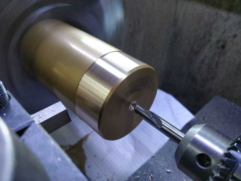
Then drilled out 12 mm:
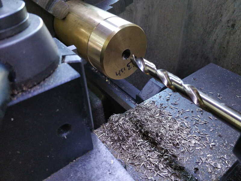
Followed by 19.5 mm (just because it's a size of Morse taper drill bit I have for some reason):
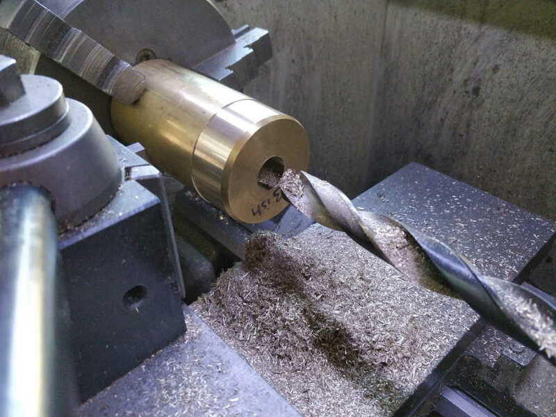
... and finally 25 mm, which is my biggest drill bit:
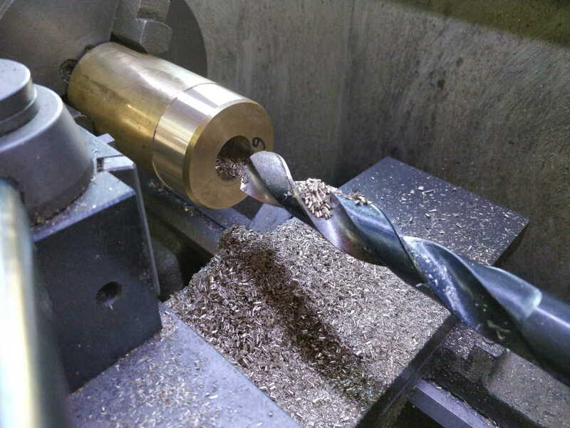
I then set up a large boring bar such it stuck out from the tool holder slightly more than the target depth of the hole:
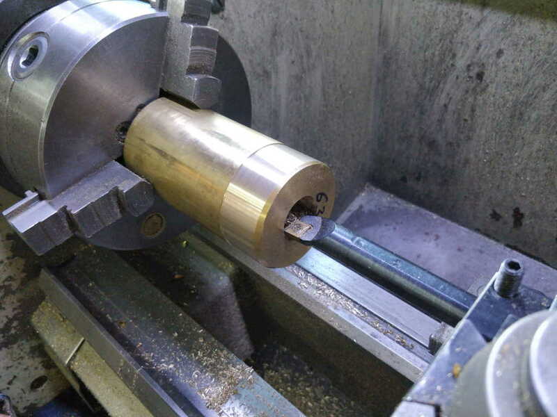
Then used the power feed to enlarge the hole to the desired depth.

As I got closer to the finished dimension, I used a (cheap and very nasty) bore gauge to measure the inside diameter.
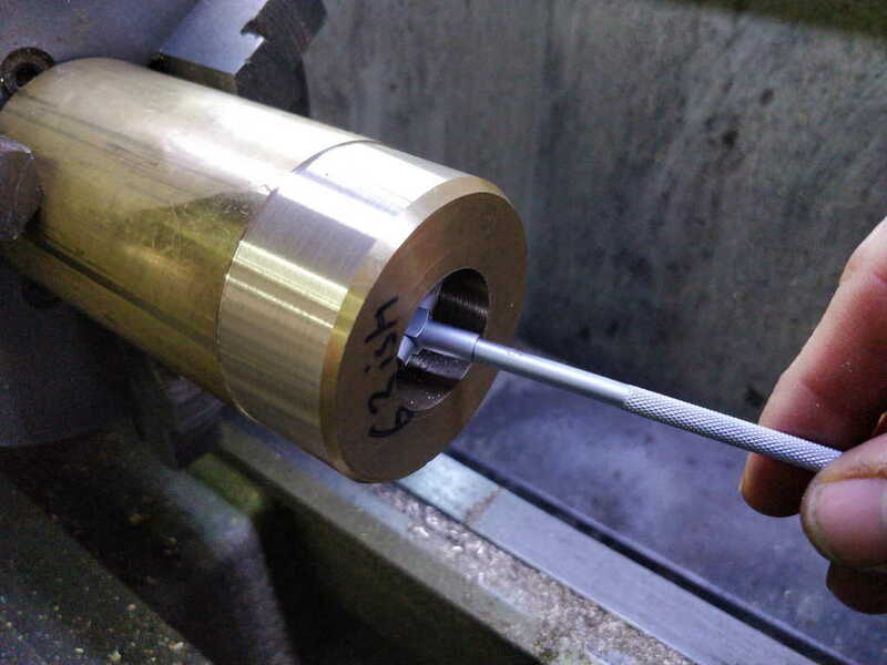
I measured with some digital calipers as at this point accuracy isn't that important. This was the last measurement I made, substantially smaller than the 30 mm target.
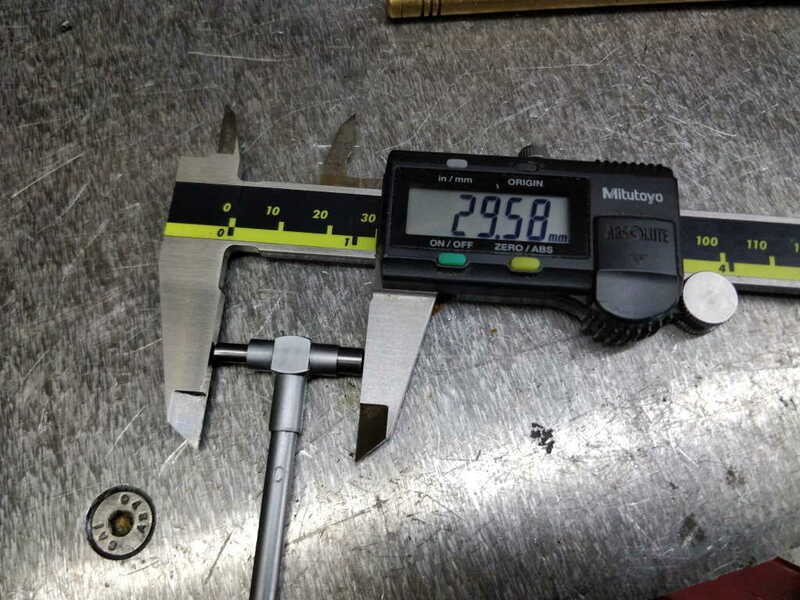
I stopped boring at this point (with the hole under-size).
Sorry if this is a bit dull: a lot of the pictures look fairly similar!
I'm starting with the vice rail bushes. The steel tube that I'm using as the rails need to be a smooth and easy sliding fit in the hole through the middle of the bush, so I took my time on this one. After making these bushes I'll probably be able to make the other parts a lot quicker.
The end face was relatively flat already, so I didn't bother facing before starting the process. I went straight for a centre drill:
Then drilled out 12 mm:
Followed by 19.5 mm (just because it's a size of Morse taper drill bit I have for some reason):
... and finally 25 mm, which is my biggest drill bit:
I then set up a large boring bar such it stuck out from the tool holder slightly more than the target depth of the hole:
Then used the power feed to enlarge the hole to the desired depth.
As I got closer to the finished dimension, I used a (cheap and very nasty) bore gauge to measure the inside diameter.
I measured with some digital calipers as at this point accuracy isn't that important. This was the last measurement I made, substantially smaller than the 30 mm target.
I stopped boring at this point (with the hole under-size).
Dr.Al
Old Oak
I then put my upside-down tool in the tool post, set the lathe to run backwards and faced off the end:
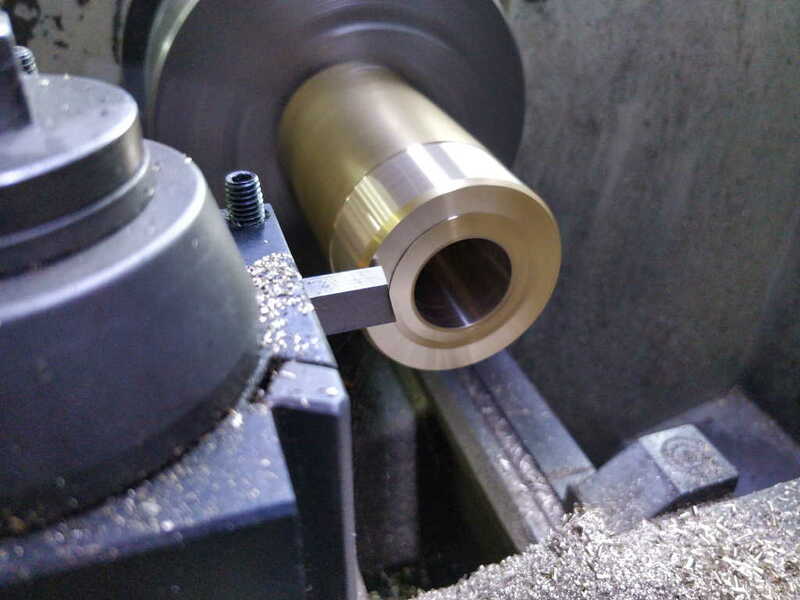
I then turned the outside diameter down to about 0.5 mm over the target diameter (40 mm).
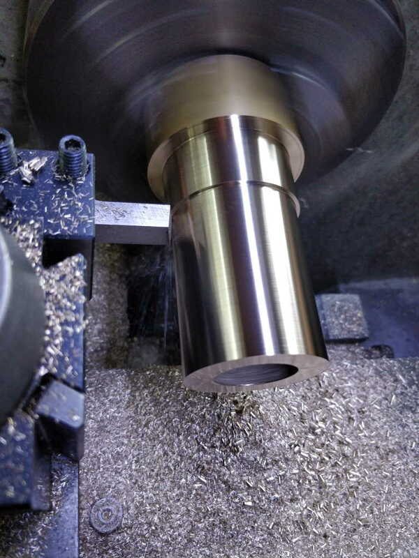
Once that was done, I wandered off and did some tidying at the other end of the workshop for half an hour while the workpiece cooled down. It's probably not **that** critical for this application (it's not exactly a bearing fit or anything), but I wanted to give myself the best chance.
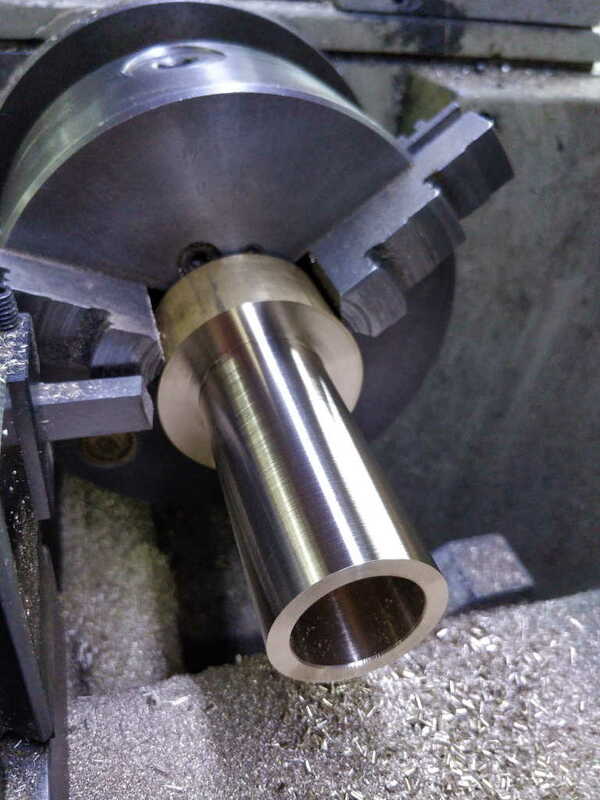
Once it was back down to room temperature (which didn't take that long as it hadn't actually got that hot), I took a final pass on the outside diameter and then faced the inside surface of the flange:
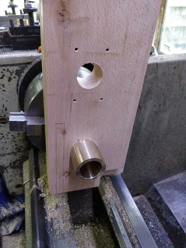
This seemed a good time for a test fit of the outside diameter in the fixed jaw:
The boring bar then went back onto the tool post and I took a lot of passes (with repeated "spring" passes at each setting of the cross-slide) to gradually sneak up on the final diameter.
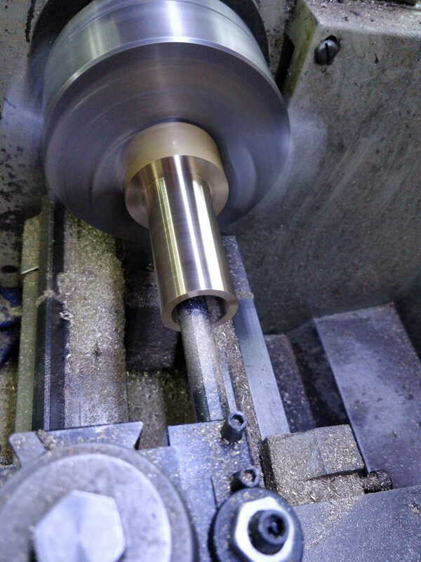
As I got close, I used the steel tube as a reference, rather than relying on the bore gauge to measure the size.
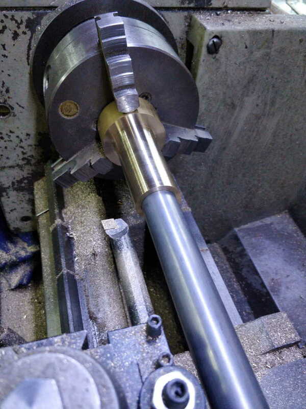
Finally, I chamfered the end to tidy it up a bit. I also chamfered the inside edge, but I just did that with a hand held deburring tool while spinning the chuck with my other hand.
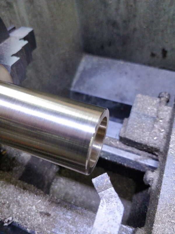
I then turned the outside diameter down to about 0.5 mm over the target diameter (40 mm).
Once that was done, I wandered off and did some tidying at the other end of the workshop for half an hour while the workpiece cooled down. It's probably not **that** critical for this application (it's not exactly a bearing fit or anything), but I wanted to give myself the best chance.
Once it was back down to room temperature (which didn't take that long as it hadn't actually got that hot), I took a final pass on the outside diameter and then faced the inside surface of the flange:
This seemed a good time for a test fit of the outside diameter in the fixed jaw:
The boring bar then went back onto the tool post and I took a lot of passes (with repeated "spring" passes at each setting of the cross-slide) to gradually sneak up on the final diameter.
As I got close, I used the steel tube as a reference, rather than relying on the bore gauge to measure the size.
Finally, I chamfered the end to tidy it up a bit. I also chamfered the inside edge, but I just did that with a hand held deburring tool while spinning the chuck with my other hand.
Dr.Al
Old Oak
Anyone still reading this?!?! :lol:
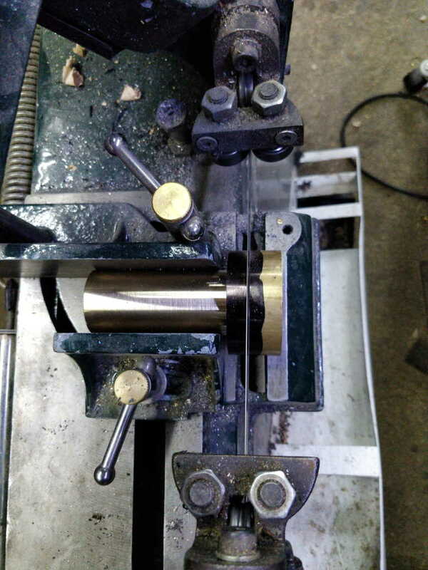
The part then came off the lathe and I scribbled over it in pen and marked the intended length of the flange. I then clamped it in the bandsaw vice and sawed off the excess:
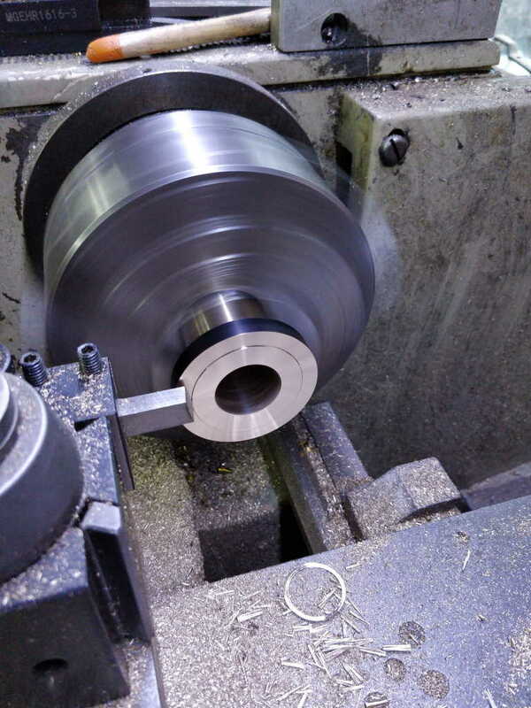
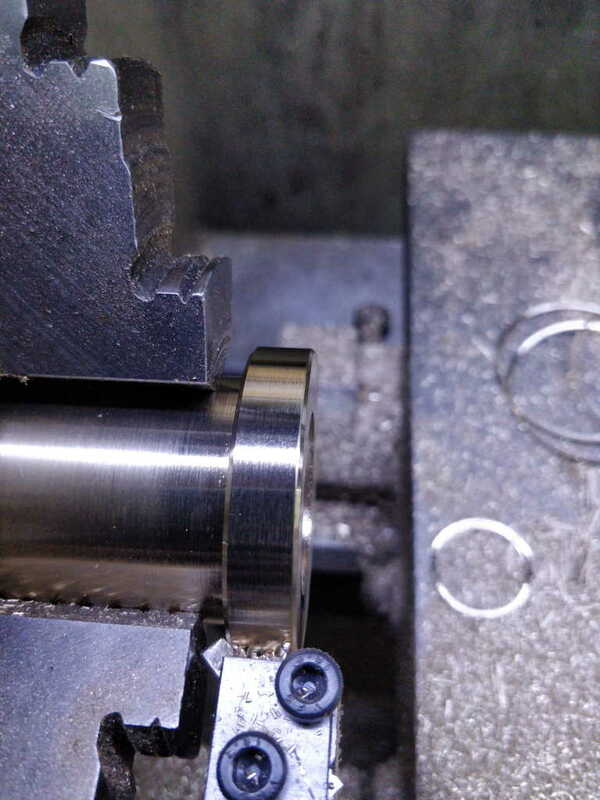
Then it was back in the chuck for facing and turning the outside diameter of the flange down to 50 mm.
Finally I used my very small chamfering tool to chamfer both outside corners of the flange and again used a hand-held deburring tool to chamfer the corner of the bore.
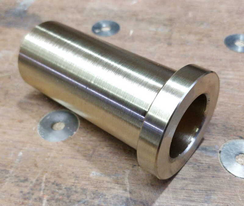
Et voila!
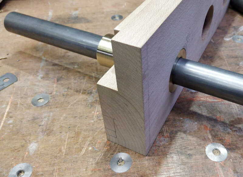
Test fit in the fixed jaw with the tube inserted.
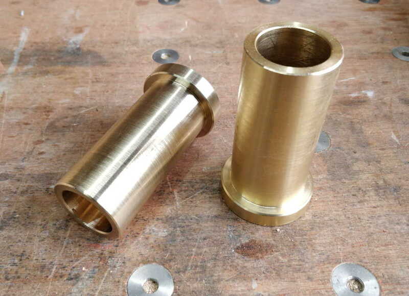
My next job is to make another one exactly the same. After that I've got a few more parts to make, but none of them are anywhere near as critical. There are a couple with critical bores, but the actual dimension isn't important, just the fact that they're parallel. I'll (later) make the steel bits that slide in the bore and I'll size them to suit the sizes of the bores in the brass parts - it's much easier to measure the OD repeatedly during turning, so I'd rather do it that way round given the choice.
The part then came off the lathe and I scribbled over it in pen and marked the intended length of the flange. I then clamped it in the bandsaw vice and sawed off the excess:
Then it was back in the chuck for facing and turning the outside diameter of the flange down to 50 mm.
Finally I used my very small chamfering tool to chamfer both outside corners of the flange and again used a hand-held deburring tool to chamfer the corner of the bore.
Et voila!
Test fit in the fixed jaw with the tube inserted.
My next job is to make another one exactly the same. After that I've got a few more parts to make, but none of them are anywhere near as critical. There are a couple with critical bores, but the actual dimension isn't important, just the fact that they're parallel. I'll (later) make the steel bits that slide in the bore and I'll size them to suit the sizes of the bores in the brass parts - it's much easier to measure the OD repeatedly during turning, so I'd rather do it that way round given the choice.

Mike G
Petrified Pine
Dr.Al":399xkgil said:Anyone still reading this?!?! :lol: .........
Oh yes indeed. Thoroughly enjoying it. This is stuff I wish I could do myself.
NickM
Old Oak
I'm reading it. I can't claim to understand it, but I'm enjoying it!
Yep I’m here. Deeply jealous and like Mike, wishing I had the time, tools and knowledge to do this kind of stuff.

Phil
Old Oak
Very impressive!
:text-+1:
With kit like that I would be building a model steam engine
TrimTheKing":14vmi7eg said:Yep I’m here. Deeply jealous and like Mike, wishing I had the time, tools and knowledge to do this kind of stuff.
:text-+1:
With kit like that I would be building a model steam engine
Dr.Al
Old Oak
Phil":xfjof4mh said:Very impressive!
TrimTheKing":xfjof4mh said:Yep I’m here. Deeply jealous and like Mike, wishing I had the time, tools and knowledge to do this kind of stuff.
:text-+1:
With kit like that I would be building a model steam engine
It is something I've thought about in the past, but there have always been other projects that tempt me more. I did make a "Coffee-Cup Powered Sterling Engine" to Jan Ridders' design† a few years ago, but I much prefer making things I've designed myself and will get used (so tools, furniture etc), so engines aren't very high on my list as a general rule.
† Jan Ridders is one of the more civilised engine designers who works in "proper" units rather than antediluvian ones.
NickM
Old Oak
Dr.Al":m47bg52c said:Phil":m47bg52c said:Very impressive!
TrimTheKing":m47bg52c said:Yep I’m here. Deeply jealous and like Mike, wishing I had the time, tools and knowledge to do this kind of stuff.
:text-+1:
With kit like that I would be building a model steam engine
It is something I've thought about in the past, but there have always been other projects that tempt me more. I did make a "Coffee-Cup Powered Sterling Engine" to Jan Ridders' design† a few years ago, but I much prefer making things I've designed myself and will get used (so tools, furniture etc), so engines aren't very high on my list as a general rule.
† Jan Ridders is one of the more civilised engine designers who works in "proper" units rather than antediluvian ones.
Although my dad has recently got more into wood turning, he has long had a passion for model engineering and has made a variety of steam engines and sterling engines. He made one which would run from the heat of your hand, but it was a bit temperamental and worked much better on a coffee cup.
My favourite thing he made is a wimshurst machine. It has contra-rotating perspex disks with aluminium segments that generate a lot of static electricity. Coupled with some laden jars it will produce some pretty spectacular sparks!
Phil
Old Oak
NickM":11wmobxb said:Dr.Al":11wmobxb said:Phil":11wmobxb said:Very impressive!
:text-+1:
With kit like that I would be building a model steam engine
It is something I've thought about in the past, but there have always been other projects that tempt me more. I did make a "Coffee-Cup Powered Sterling Engine" to Jan Ridders' design† a few years ago, but I much prefer making things I've designed myself and will get used (so tools, furniture etc), so engines aren't very high on my list as a general rule.
† Jan Ridders is one of the more civilised engine designers who works in "proper" units rather than antediluvian ones.
Although my dad has recently got more into wood turning, he has long had a passion for model engineering and has made a variety of steam engines and sterling engines. He made one which would run from the heat of your hand, but it was a bit temperamental and worked much better on a coffee cup.
My favourite thing he made is a wimshurst machine. It has contra-rotating perspex disks with aluminium segments that generate a lot of static electricity. Coupled with some laden jars it will produce some pretty spectacular sparks!
This has just reminded me that somewhere in a box in the garage is a small basic model Mamod engine
Dr.Al
Old Oak
I spent this afternoon turning lots and lots of brass. I started by putting the vice rail bush in the photocopier:
With both of them complete I could do a quick test fit of the standard vice parts to make sure it slides okay. It's difficult to tell at the moment (without the screw present), but it certainly moves, so that's a good start!
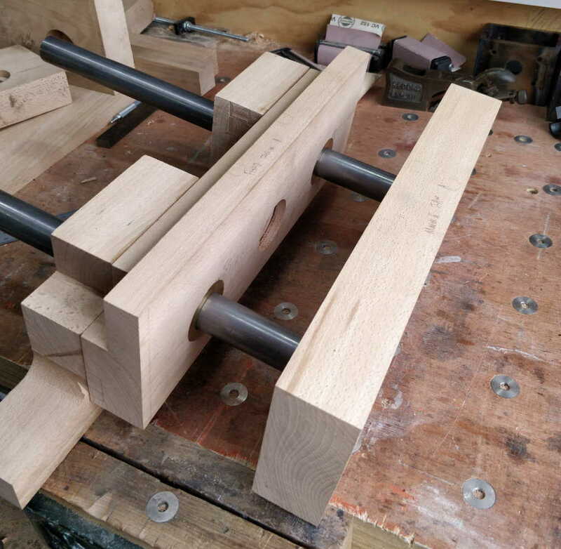
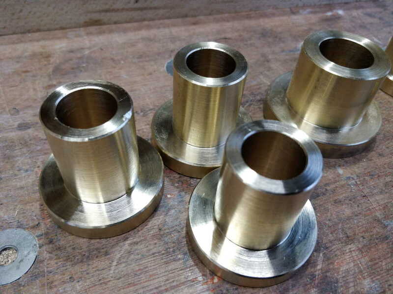
I then got going on the other (simpler) flanged bushes. These were made in a similar way to the vice rail bushes with a few minor differences:
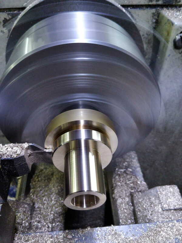
The first one I made was the bearing for the thread in the standard vice. This one will have a (similar looking) steel part running inside it to give a (hopefully) smooth action to the screw and also to make sure the jaw moves in and out with the movement of the screw:
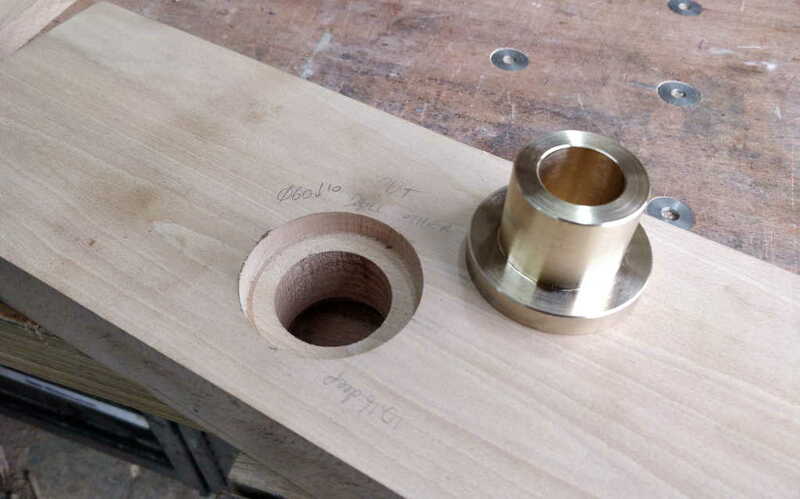
There were then three identical flanged bushes in which the threaded rod will slide. The bore of these is 19.8 mm as the threaded rod I've got seems to be 19.7 mm diameter.
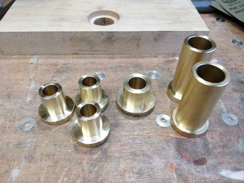
Slightly irritatingly, I dropped one of the flanges on the floor and it got a "dink" in one end. I've decided not to worry about it as this dink is in the end that's hidden between the inside face of the fixed jaw and the steel body of the vice mechanism. No-one will ever see it.
With both of them complete I could do a quick test fit of the standard vice parts to make sure it slides okay. It's difficult to tell at the moment (without the screw present), but it certainly moves, so that's a good start!
I then got going on the other (simpler) flanged bushes. These were made in a similar way to the vice rail bushes with a few minor differences:
- Accuracy was far less important, so I bored the hole out in one go (rather than letting it cool down part way through).
- The parts are much shorter, so I turned the larger diameter at the same time as the smaller diameter.
- I parted the pieces off in the lathe rather than using the bandsaw. I still flipped them round and faced the parted-off end, but doing it this way was a bit quicker and didn't involve worrying about how to hold relatively short, stepped pieces in the bandsaw:
The first one I made was the bearing for the thread in the standard vice. This one will have a (similar looking) steel part running inside it to give a (hopefully) smooth action to the screw and also to make sure the jaw moves in and out with the movement of the screw:
There were then three identical flanged bushes in which the threaded rod will slide. The bore of these is 19.8 mm as the threaded rod I've got seems to be 19.7 mm diameter.
Slightly irritatingly, I dropped one of the flanges on the floor and it got a "dink" in one end. I've decided not to worry about it as this dink is in the end that's hidden between the inside face of the fixed jaw and the steel body of the vice mechanism. No-one will ever see it.
Dr.Al
Old Oak
Here are all of the brass parts fitted (but not adhered) into their holes:
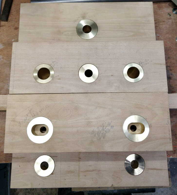
This test did highlight some issues unfortunately. For two of the parts (one of the thread bushes for the dual-screw vice and the central bearing for the standard vice), the larger hole in which the flange sits isn't concentric with the central bore. It's not actually that important as it's the central bore that has to be (and is) in the right place to ensure it works properly, it just means that there's a small (0.5 mm maybe?) gap visible on one side of the bush.
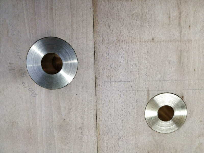
This is one of those things that no-one other than me will ever notice (especially once the hand wheel and washer are there), but I'm trying to work out how much it's going to annoy me and whether to do anything about it (and if so, what). The only thought I've had at the moment is to mount the parts back in the mill vice, use a DTI on the inner bore of the brass bush to get the XY table in exactly the right place and then make the hole a bit bigger (somehow - I suspect my boring head would leave an awfully ragged edge). I could then add a contrasting wood (if it's thin and I can figure out how to make it) or aluminium ring around the brass part to make it look deliberate!
I'll ponder on that one; I think it will be a heck of a lot of work...
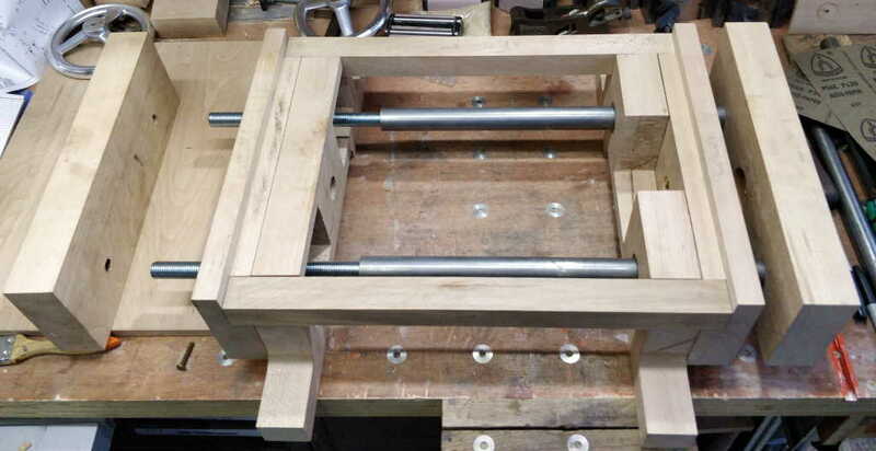
With all the brass parts made, I did a test assembly of the bench to see what it's looking like.
I also gave the lathe a bit of a clear up and put all the swarf in some freezer bags for saving. I think I've produced more brass swarf in the last two days than I have in the rest of my metalworking life put together.
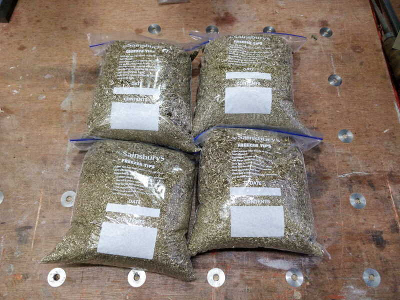
That lot weighs just over 7.9 kg! :shock:
With all the turned brass bits complete, the next job is probably to work on the steel pieces:
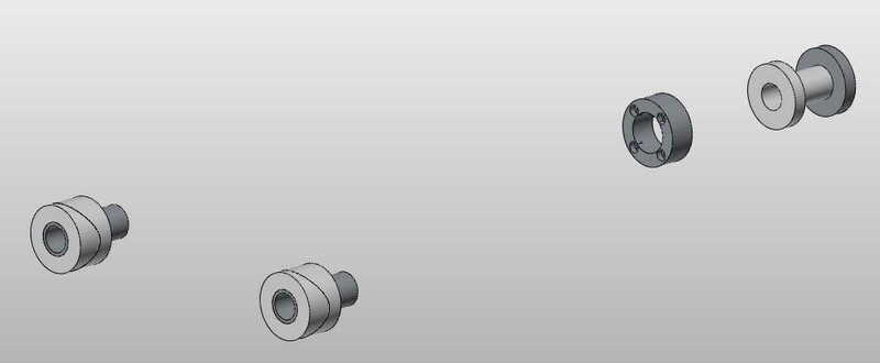
Three of these (the darker coloured two tubes on the left and the lighter coloured flanged tube on the right) have threaded holes through, one has some counterbored holes drilled in an awkward location (because this part was an afterthought!), one is a simple washer and four are an attempt at a couple of pseudo-spherical-washers to allow angular clamping. I'll leave those latter parts to last as (if they don't work) they can be replaced with plain washers as I don't expect to do much angular clamping.
This test did highlight some issues unfortunately. For two of the parts (one of the thread bushes for the dual-screw vice and the central bearing for the standard vice), the larger hole in which the flange sits isn't concentric with the central bore. It's not actually that important as it's the central bore that has to be (and is) in the right place to ensure it works properly, it just means that there's a small (0.5 mm maybe?) gap visible on one side of the bush.
This is one of those things that no-one other than me will ever notice (especially once the hand wheel and washer are there), but I'm trying to work out how much it's going to annoy me and whether to do anything about it (and if so, what). The only thought I've had at the moment is to mount the parts back in the mill vice, use a DTI on the inner bore of the brass bush to get the XY table in exactly the right place and then make the hole a bit bigger (somehow - I suspect my boring head would leave an awfully ragged edge). I could then add a contrasting wood (if it's thin and I can figure out how to make it) or aluminium ring around the brass part to make it look deliberate!
I'll ponder on that one; I think it will be a heck of a lot of work...
With all the brass parts made, I did a test assembly of the bench to see what it's looking like.
I also gave the lathe a bit of a clear up and put all the swarf in some freezer bags for saving. I think I've produced more brass swarf in the last two days than I have in the rest of my metalworking life put together.
That lot weighs just over 7.9 kg!
:shock: With all the turned brass bits complete, the next job is probably to work on the steel pieces:
Three of these (the darker coloured two tubes on the left and the lighter coloured flanged tube on the right) have threaded holes through, one has some counterbored holes drilled in an awkward location (because this part was an afterthought!), one is a simple washer and four are an attempt at a couple of pseudo-spherical-washers to allow angular clamping. I'll leave those latter parts to last as (if they don't work) they can be replaced with plain washers as I don't expect to do much angular clamping.

Dr.Al
Old Oak
sunnybob":22o64wtr said:Thats £15 worth of scrap brass.
Yep. It's a good job I got this brass out of a skip and for free or I never would have used so much of it in this project!
Dr.Al
Old Oak
I woke up this morning firmly of the opinion that the non-concentricity of the hole on the moving jaw of the standard vice was something I can't live with. The one on the fixed jaw of the dual-screw vice I think I can - it's only really visible if you look really closely, unlike the one on the moving jaw which is a much bigger gap and looks (in my opinion) awful.
To that end, I started this morning by getting a big of steel the same size as the inner bore of the brass insert and drilling and tapping it for an M5 screw.
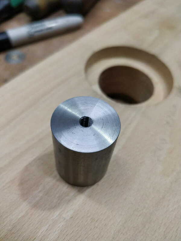
I then fitted an M5 cap screw into one of the threaded holes on my router that is designed for holding guide bushes in place:
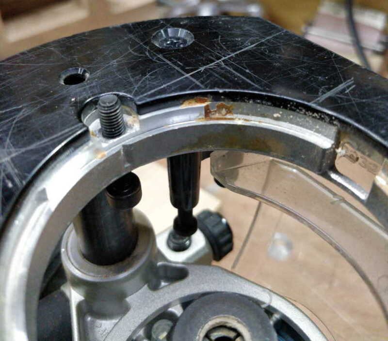
I could then screw the block of steel into place.
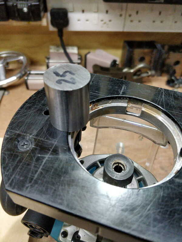
Sliding the brass "bearing housing" onto the bush allowed me to pick a router bit that wouldn't quite touch the brass.
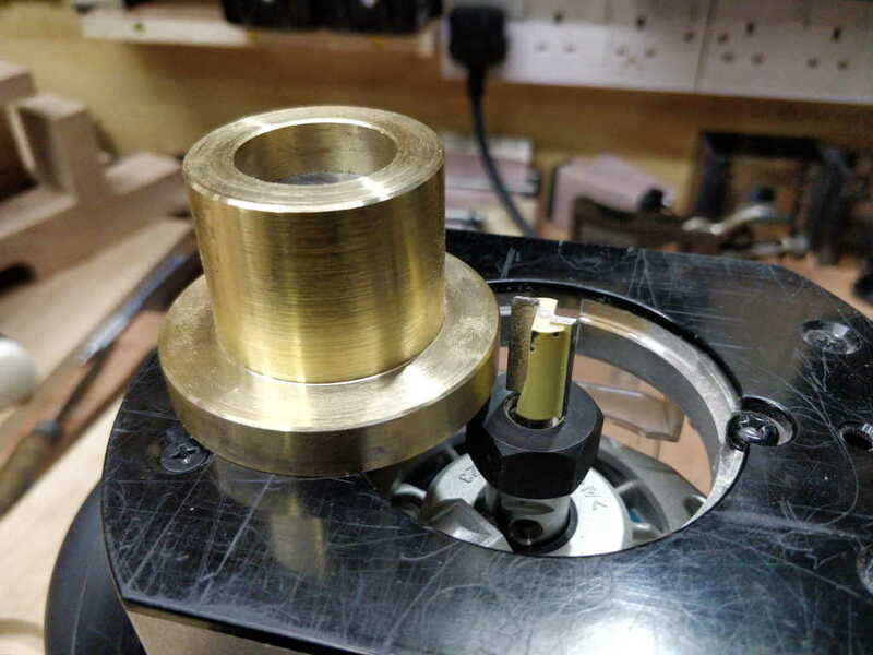
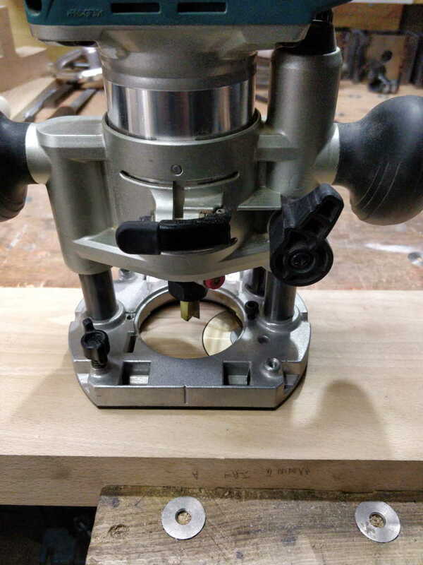
I could then drop the whole lot onto the moving jaw to rout a circle:
That left a small ridge all the way around the inside of the hole.
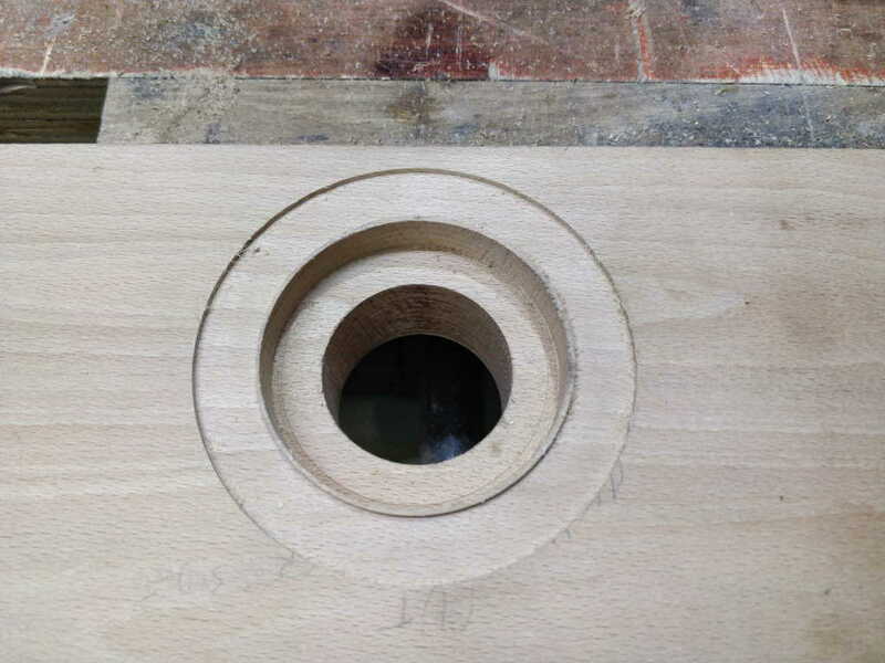
Which I took off with a chisel.
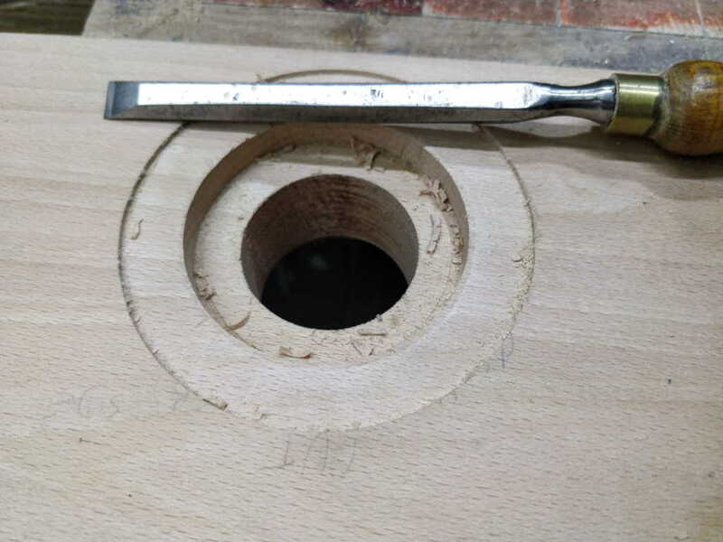
To that end, I started this morning by getting a big of steel the same size as the inner bore of the brass insert and drilling and tapping it for an M5 screw.
I then fitted an M5 cap screw into one of the threaded holes on my router that is designed for holding guide bushes in place:
I could then screw the block of steel into place.
Sliding the brass "bearing housing" onto the bush allowed me to pick a router bit that wouldn't quite touch the brass.
I could then drop the whole lot onto the moving jaw to rout a circle:
That left a small ridge all the way around the inside of the hole.
Which I took off with a chisel.
Dr.Al
Old Oak
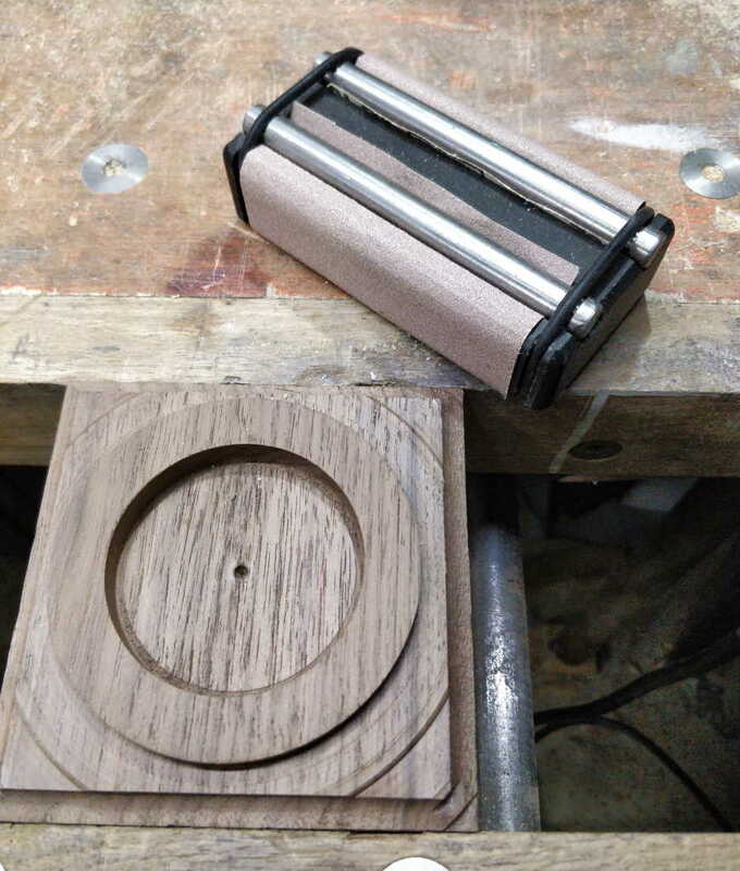
Last year for my other half's birthday, I made her some brass pattern weights and a stand for them to sit on. When I was making the stand I had a test run for the base and wasn't very happy with it, so it got tossed into the "might-be-useful-at-some-point" drawer. Today it was useful!
I fitted the four jaw chuck to the lathe, covered the ways with a big rag and fitted the offcut of American Black Walnut.
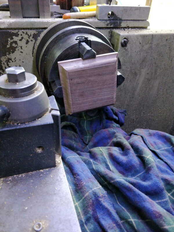
I used the same bargain-basement Forstner bit that I'd used for the original hole to make a central hole that should fit the brass bearing housing thing.
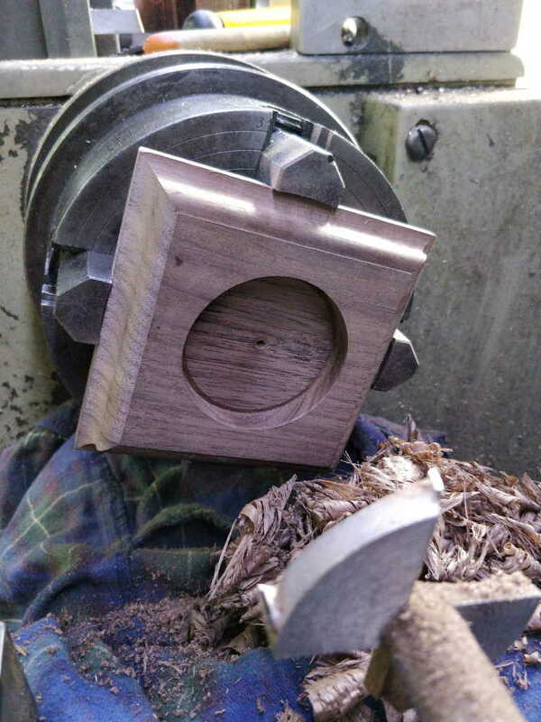
I then faced the block off and turned a portion to size. Facing left a pretty awful finish, but then I was using a tool ground for aluminium, not walnut!
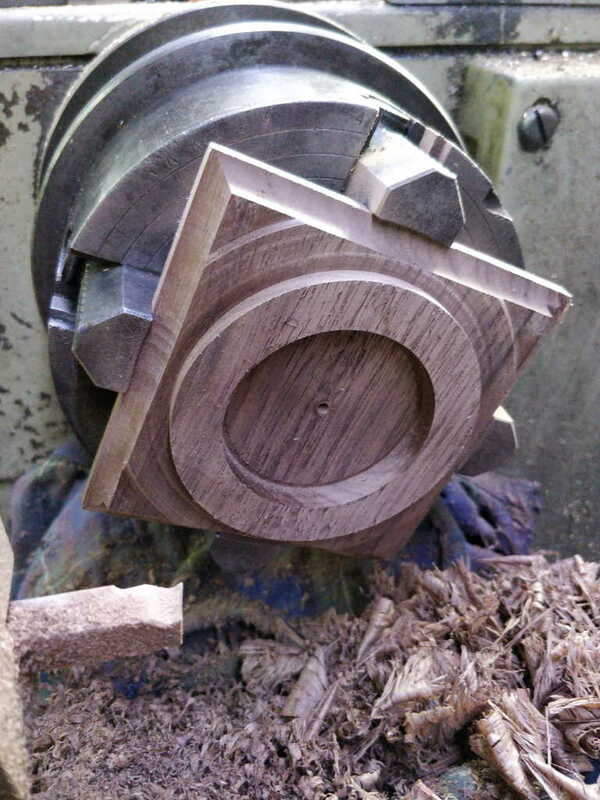
With the block removed from the lathe, I gave it a bit of a rub with some sandpaper.
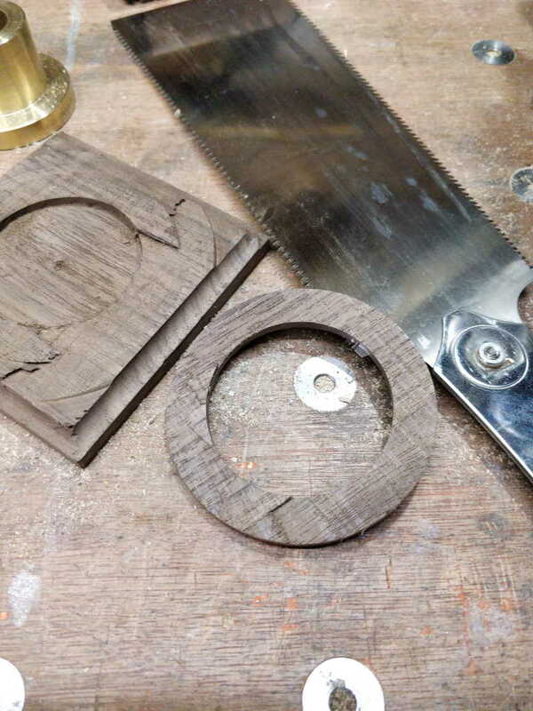
I then used a saw to separate the ring from the rest of the block.
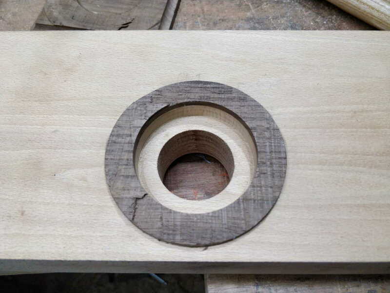
That could then be glued into place, sanded side down.
Once the glue was dry, I used my flush trim saw to trim it down to length. The masking tape was intended to lift the saw up a bit and make sure it was still proud after trimming:
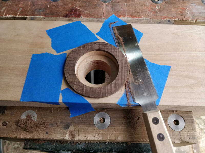
That didn't work especially well and I managed to undercut the walnut a bit, so I used a #5 plane and planed the whole surface of the moving jaw down until everything was flush:
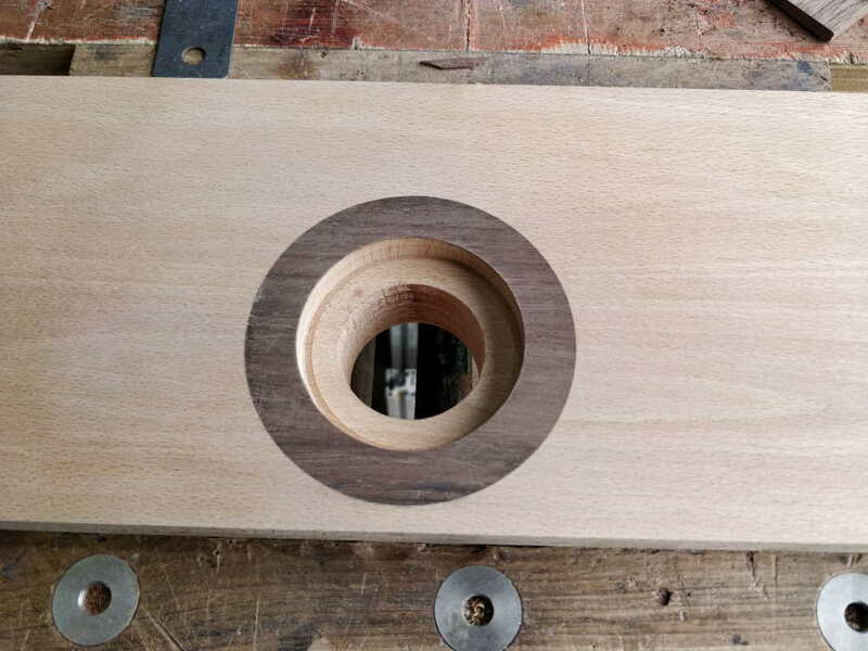
Here it is with the brass bearing block in place. I'm much happier with how this looks. It'll probably look even better if I oil the moving jaw.
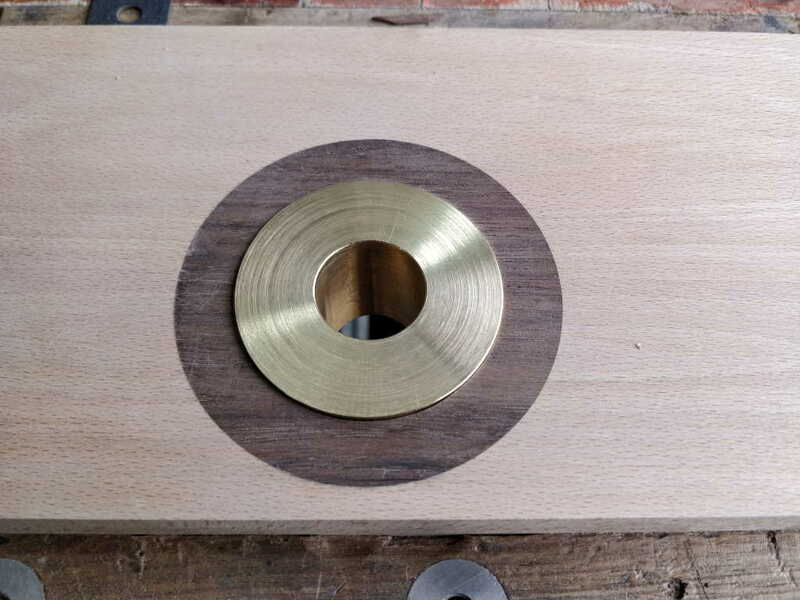
The brass is now slightly proud of the surface of the wood, but I quite like how that looks and, being on the outside of the jaw, it won't affect function.
I fitted the four jaw chuck to the lathe, covered the ways with a big rag and fitted the offcut of American Black Walnut.
I used the same bargain-basement Forstner bit that I'd used for the original hole to make a central hole that should fit the brass bearing housing thing.
I then faced the block off and turned a portion to size. Facing left a pretty awful finish, but then I was using a tool ground for aluminium, not walnut!
With the block removed from the lathe, I gave it a bit of a rub with some sandpaper.
I then used a saw to separate the ring from the rest of the block.
That could then be glued into place, sanded side down.
Once the glue was dry, I used my flush trim saw to trim it down to length. The masking tape was intended to lift the saw up a bit and make sure it was still proud after trimming:
That didn't work especially well and I managed to undercut the walnut a bit, so I used a #5 plane and planed the whole surface of the moving jaw down until everything was flush:
Here it is with the brass bearing block in place. I'm much happier with how this looks. It'll probably look even better if I oil the moving jaw.
The brass is now slightly proud of the surface of the wood, but I quite like how that looks and, being on the outside of the jaw, it won't affect function.
Dr.Al
Old Oak
With the concentricity problem fixed, I could get on with some of the steel parts. I started by putting a bit of 50 mm EN1A into the three jaw chuck and pulling out my infrequently used fixed steady. The stock is too big to go through the bore of the chuck and it would be quite wasteful to cut a length off as I'd need an extra bit to be held in the chuck and that extra bit might end up being too short to be useful.
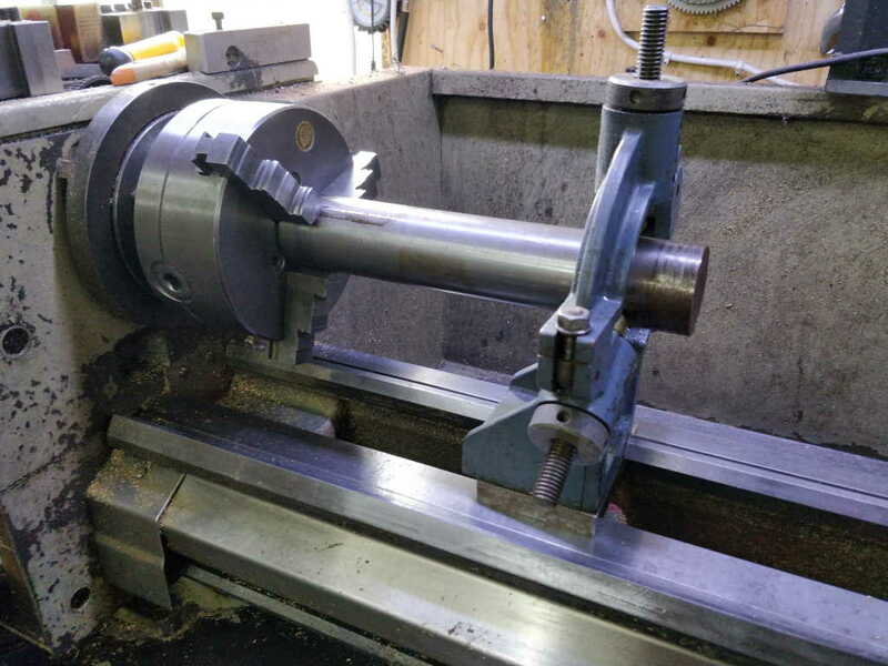
With that all set up (and well lubricated), I spot drilled the centre point, then drilled it out 6 mm, 12 mm and 16 mm to a depth of about 70 mm.
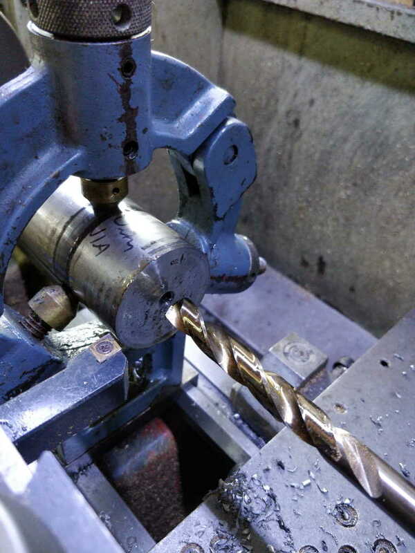
I then bored the hole to 17.75 mm, which is tapping size for 70% thread engagement on a M20×2.5 threaded hole.
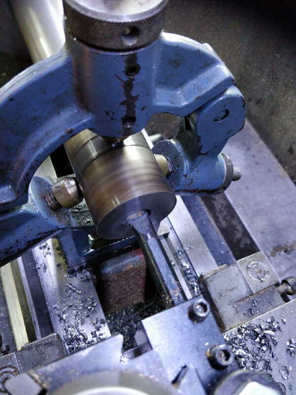
I then set the lathe up for thread cutting and used the only tool I could find in my collection that would cut an internal thread with such a coarse pitch. Unfortunately, it's a right-hand threading tool so I had to cut the thread in this blind hole with the lathe running forwards and the tool the normal way up. I generally prefer to cut threads with the lathe running backwards as the tool exits the hole at the end of the cut rather than (potentially) running into the bottom of the hole.
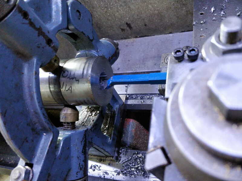
I didn't enjoy that much (I much prefer finer pitch threads!) and it's making me rethink the equivalent parts for the dual-screw vice. I may either decide to do them as simple plain sleeves and epoxy them in place or I might buy a tap to make life a bit easier.
Anyway, with that done, I faced the end and turned a short section on the end (to get rid of the rusty surface on the end of the bar):
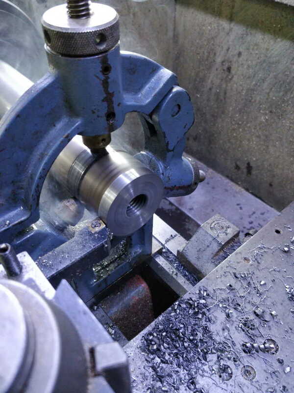
I then parted off...
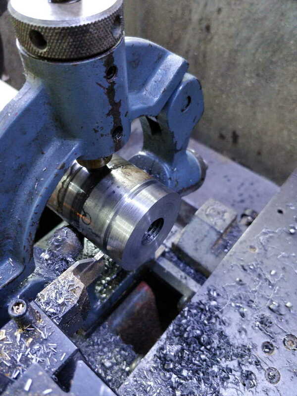
... pausing part way through the parting operation to chamfer the edges:
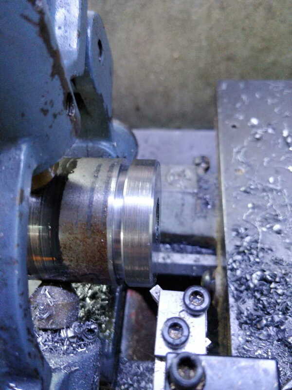
The parted off face needs a bit of work (my parting results are a bit hit-and-miss), but that'll do for now...
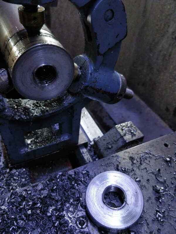
With that all set up (and well lubricated), I spot drilled the centre point, then drilled it out 6 mm, 12 mm and 16 mm to a depth of about 70 mm.
I then bored the hole to 17.75 mm, which is tapping size for 70% thread engagement on a M20×2.5 threaded hole.
I then set the lathe up for thread cutting and used the only tool I could find in my collection that would cut an internal thread with such a coarse pitch. Unfortunately, it's a right-hand threading tool so I had to cut the thread in this blind hole with the lathe running forwards and the tool the normal way up. I generally prefer to cut threads with the lathe running backwards as the tool exits the hole at the end of the cut rather than (potentially) running into the bottom of the hole.
I didn't enjoy that much (I much prefer finer pitch threads!) and it's making me rethink the equivalent parts for the dual-screw vice. I may either decide to do them as simple plain sleeves and epoxy them in place or I might buy a tap to make life a bit easier.
Anyway, with that done, I faced the end and turned a short section on the end (to get rid of the rusty surface on the end of the bar):
I then parted off...
... pausing part way through the parting operation to chamfer the edges:
The parted off face needs a bit of work (my parting results are a bit hit-and-miss), but that'll do for now...
Dr.Al
Old Oak
I then slid the travelling steady along a bit and turned the body of the threaded sleeve down to 25.5 mm.
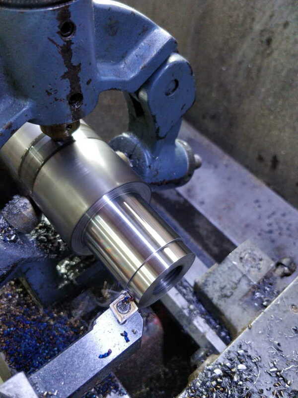
Then it was time for lunch while it all cooled down. My first postprandial task was then to take the final cuts to bring the shaft down to be a smooth running fit in the bearing housing thing.
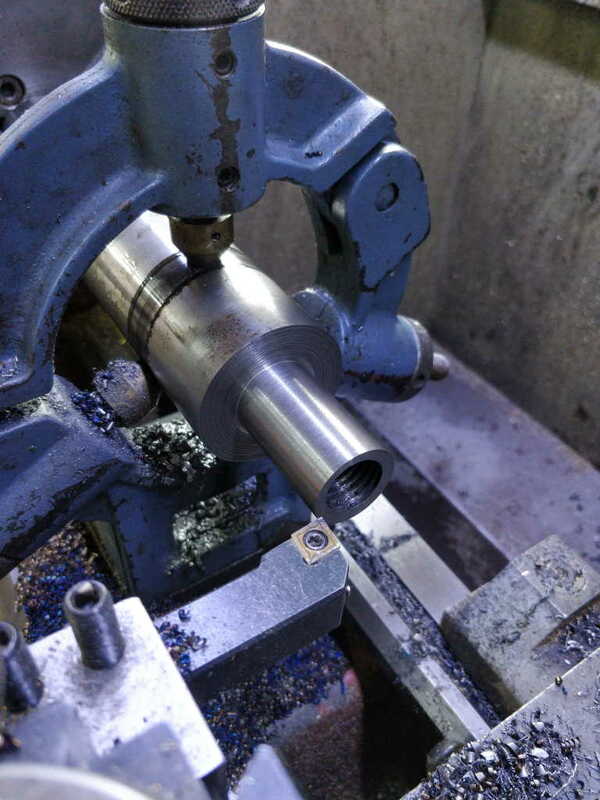
A quick chamfer of the exposed corners...
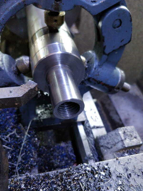
... and it was ready for a test fit of the sleeve.
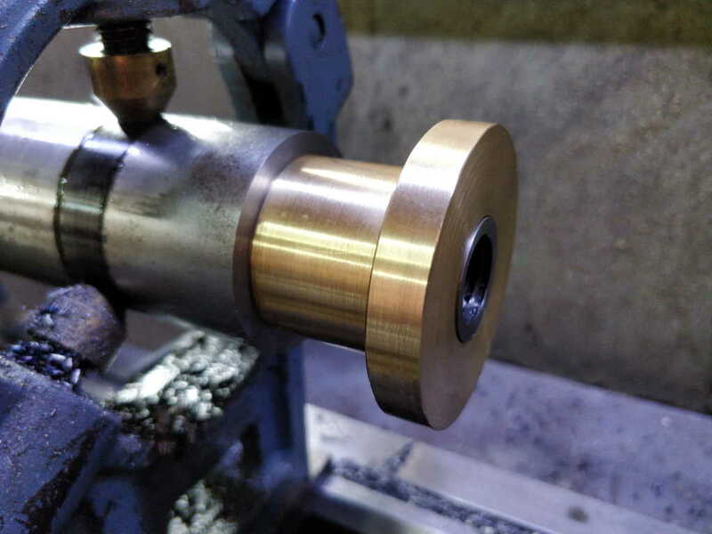
The test fit showed that it was about 0.5 mm longer than the bearing housing. It needs to be longer so that it doesn't jam up when everything's tightened up, but that was a bit too loose so I faced the end a little and brought the difference down to about 0.15 mm.
I then inserted a short length of threaded rod into the hole:
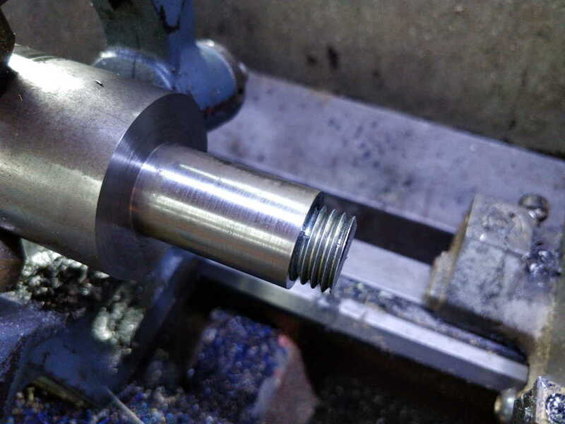
I could then mount the parted off washer onto the end and sort out the rough face.
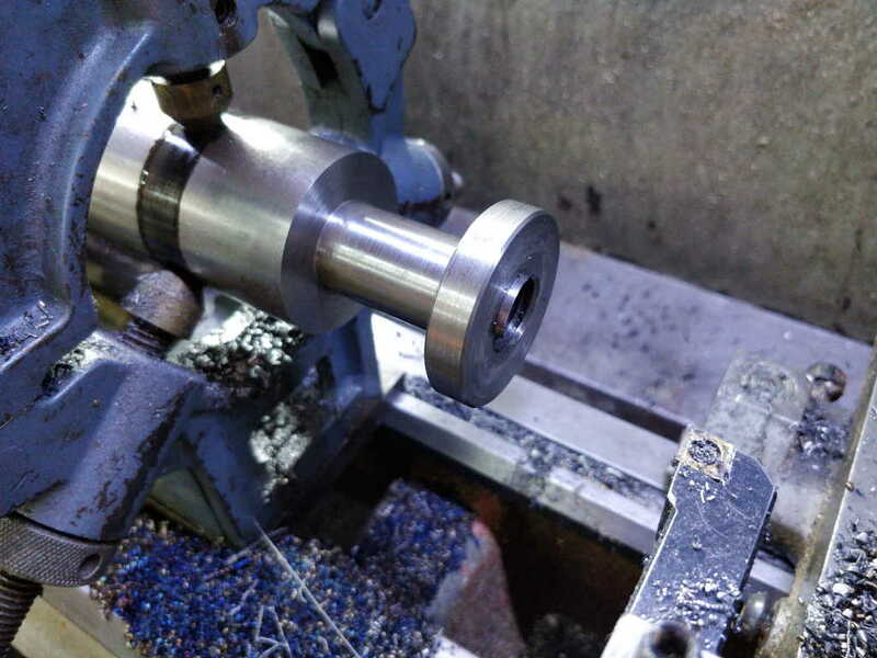
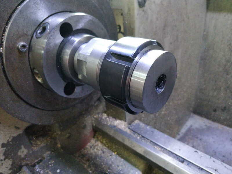
To finish off the lathe work on these parts, I put my home-made ER40 collet chuck in the headstock and faced the outside edge to the right length and chamfered.
Then it was time for lunch while it all cooled down. My first postprandial task was then to take the final cuts to bring the shaft down to be a smooth running fit in the bearing housing thing.
A quick chamfer of the exposed corners...
... and it was ready for a test fit of the sleeve.
The test fit showed that it was about 0.5 mm longer than the bearing housing. It needs to be longer so that it doesn't jam up when everything's tightened up, but that was a bit too loose so I faced the end a little and brought the difference down to about 0.15 mm.
I then inserted a short length of threaded rod into the hole:
I could then mount the parted off washer onto the end and sort out the rough face.
To finish off the lathe work on these parts, I put my home-made ER40 collet chuck in the headstock and faced the outside edge to the right length and chamfered.
Dr.Al
Old Oak
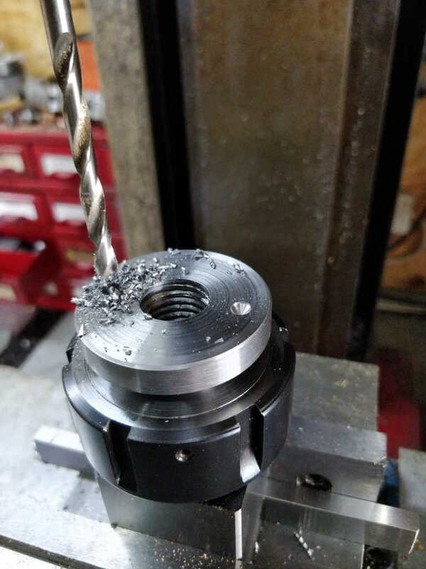
The threaded sleeve was then mounted in a collet block on the milling machine and two holes were spotted and drilled. These will be used with an angle-grinder style pin spanner to tighten the sleeve onto the threaded rod.
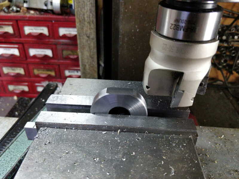
Similarly, I mounted the washer in the mill vice and milled a couple of flats:
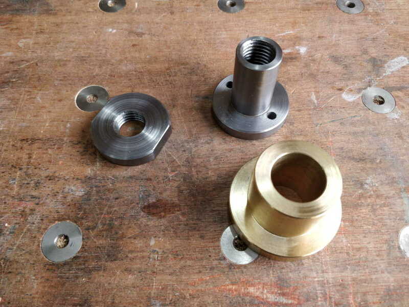
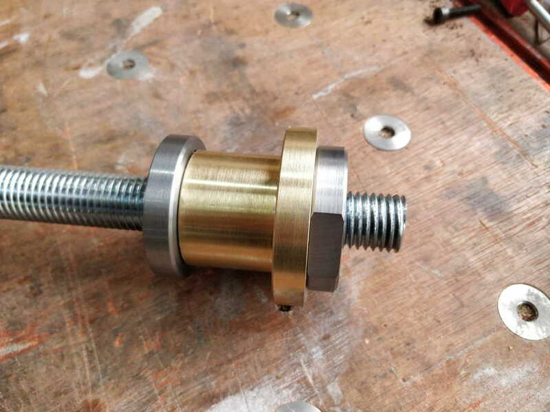
These are all the parts that make up the bearing for the standard vice:
Here they are mounted onto a bit of threaded rod to show how they fit together - in this set-up, the brass part can spin freely.
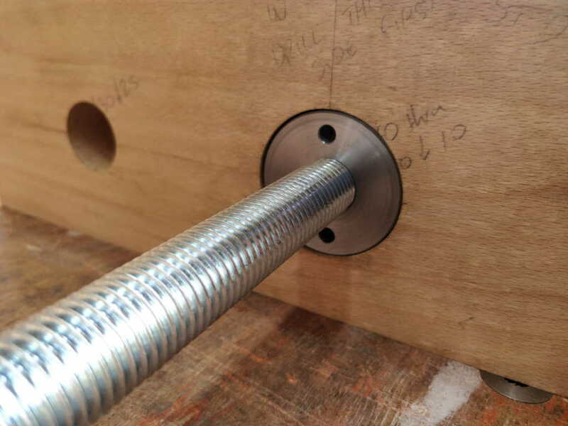
This is what they look like in the moving jaw - the brass part will be glued into the moving jaw but the other parts will be free to rotate.
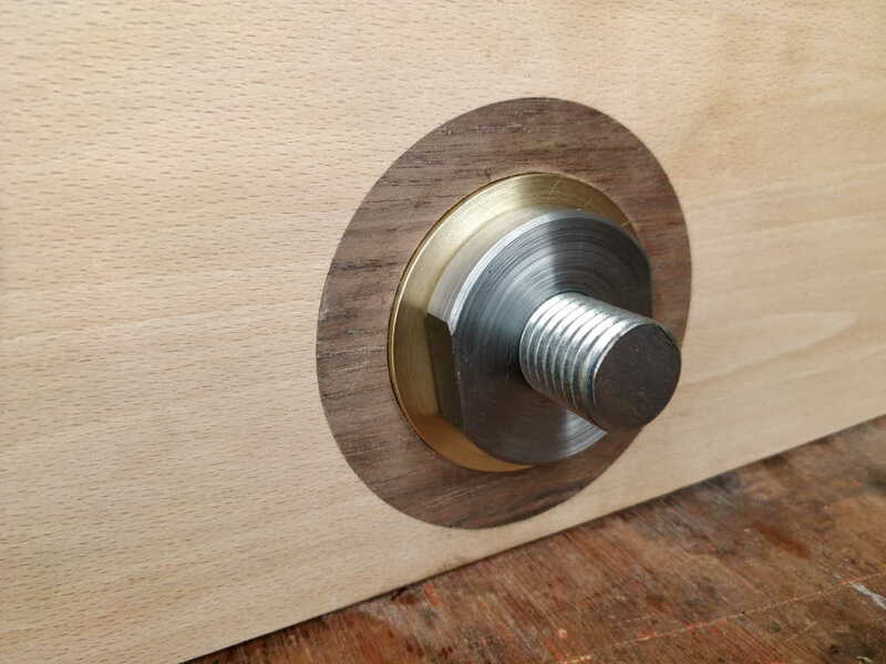
Here you can see the pin spanner holes in the threaded sleeve and where they'll sit on the inside face of the moving jaw. The face of the threaded sleeve is slightly below the surface of the beech.
Similarly, I mounted the washer in the mill vice and milled a couple of flats:
These are all the parts that make up the bearing for the standard vice:
Here they are mounted onto a bit of threaded rod to show how they fit together - in this set-up, the brass part can spin freely.
This is what they look like in the moving jaw - the brass part will be glued into the moving jaw but the other parts will be free to rotate.
Here you can see the pin spanner holes in the threaded sleeve and where they'll sit on the inside face of the moving jaw. The face of the threaded sleeve is slightly below the surface of the beech.
Dr.Al
Old Oak
Last job of the day was to start work on one of the hand-wheels. After playing around with a few different approaches, I concluded that the best way to mount the hand-wheel on the lathe was with the jaws pressing against the inside of the outer rim.
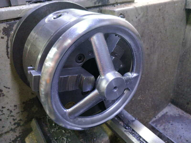
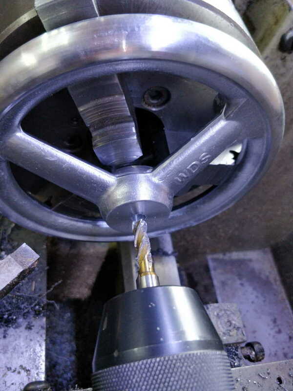
The pilot hole wasn't concentric with the outer rim (I guess it was drilled relative to the inner hub), so to save my drill bits from having a hard life, I ran an end mill through to true the hole up:
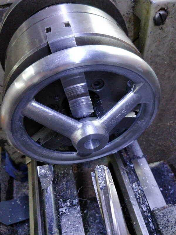
I then drilled the hole out to 12 mm, bored it out to 15.7 mm and put a reamer through it to bring it to 16 mm. The choice of 16 mm was simply because I have a 16 mm reamer and I figured that would give a smooth finish for attaching it to the threaded rod.
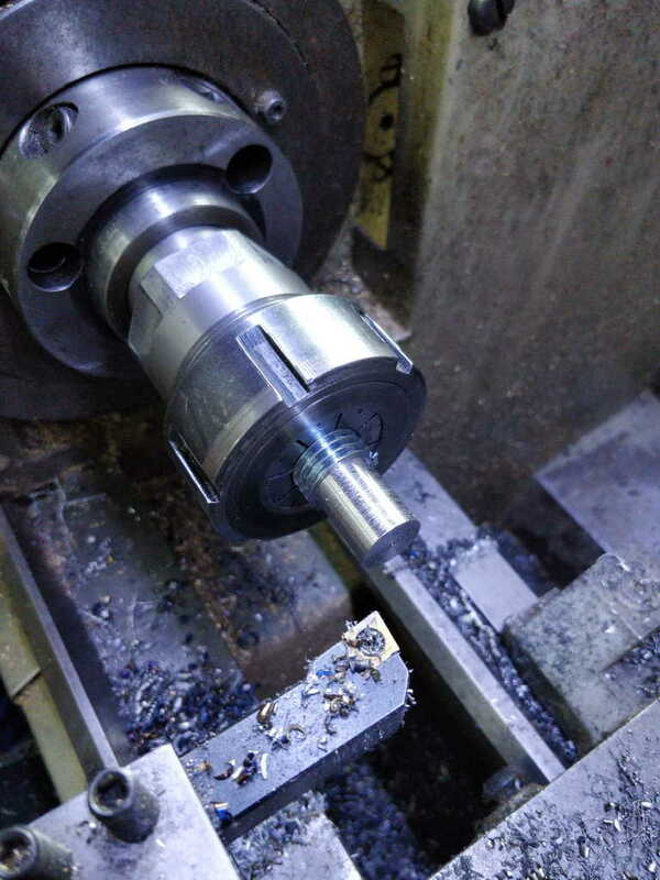
I mounted a length of threaded rod in my collet chuck, faced it and turned a portion down to 16 mm.
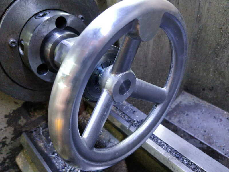
I could then check that the hand-wheel fitted well:
I then transferred the set-up over to the collet block on the milling vice and tried to figure out how to drill a cross-pin hole! I glued the hand-wheel in place with some Loctite 603 and used a ER16 collet chuck to hold a 3 mm spotting drill and then 3 mm drill bit. I think the roll-pin I was using was supposed to be used with a 3.2 mm drill bit, but I don't have a 4 mm ER16 collet, so 3 mm was the only option. All of my other chucks would have hit the hand-wheel outer rim.
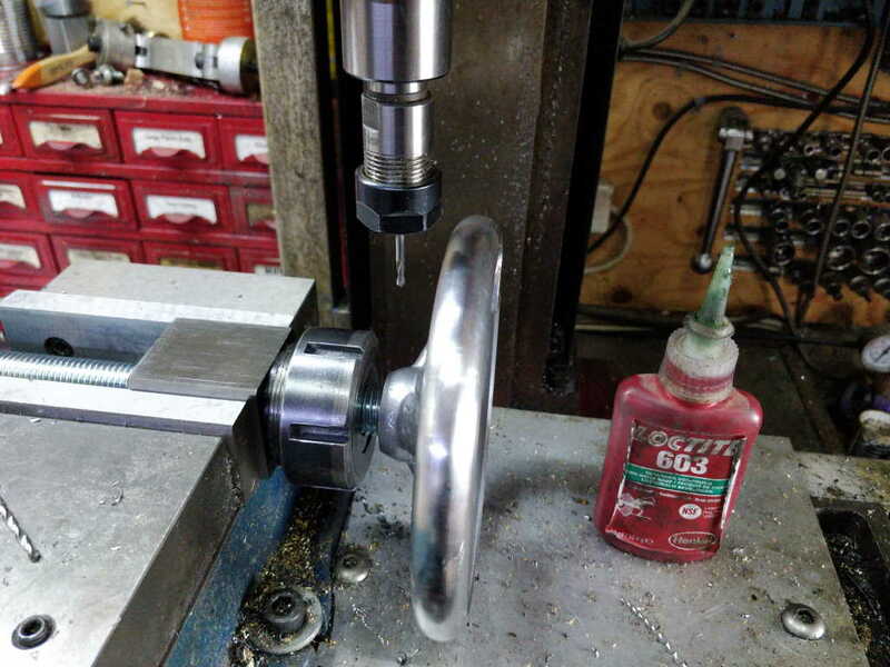
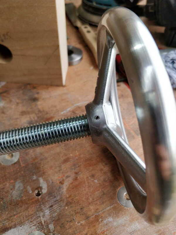
Thankfully I didn't have to open up the hole to 3.2 mm manually: the cross pin went in fairly easily:
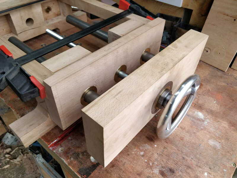
With that complete, it felt like it was time for a trial assembly again:
I think the first job for tomorrow will be a bit of a tidy-up: I've made a bit of a mess everywhere!
The pilot hole wasn't concentric with the outer rim (I guess it was drilled relative to the inner hub), so to save my drill bits from having a hard life, I ran an end mill through to true the hole up:
I then drilled the hole out to 12 mm, bored it out to 15.7 mm and put a reamer through it to bring it to 16 mm. The choice of 16 mm was simply because I have a 16 mm reamer and I figured that would give a smooth finish for attaching it to the threaded rod.
I mounted a length of threaded rod in my collet chuck, faced it and turned a portion down to 16 mm.
I could then check that the hand-wheel fitted well:
I then transferred the set-up over to the collet block on the milling vice and tried to figure out how to drill a cross-pin hole! I glued the hand-wheel in place with some Loctite 603 and used a ER16 collet chuck to hold a 3 mm spotting drill and then 3 mm drill bit. I think the roll-pin I was using was supposed to be used with a 3.2 mm drill bit, but I don't have a 4 mm ER16 collet, so 3 mm was the only option. All of my other chucks would have hit the hand-wheel outer rim.
Thankfully I didn't have to open up the hole to 3.2 mm manually: the cross pin went in fairly easily:
With that complete, it felt like it was time for a trial assembly again:
I think the first job for tomorrow will be a bit of a tidy-up: I've made a bit of a mess everywhere!
Dr.Al
Old Oak
I started this morning with a bit of a tidy-up and then sorted out the other two hand-wheels. I didn't bother taking photos of that process as it was exactly the same as the first hand-wheel.
I then fitted a cut-off bit of 50 mm EN1A into the chuck:
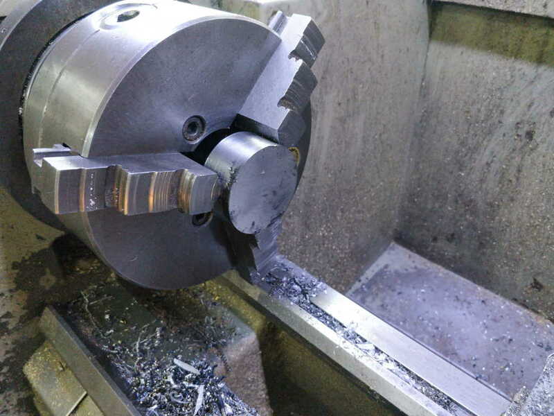
I faced the end, chamfered the corners and then spotted the centre hole.

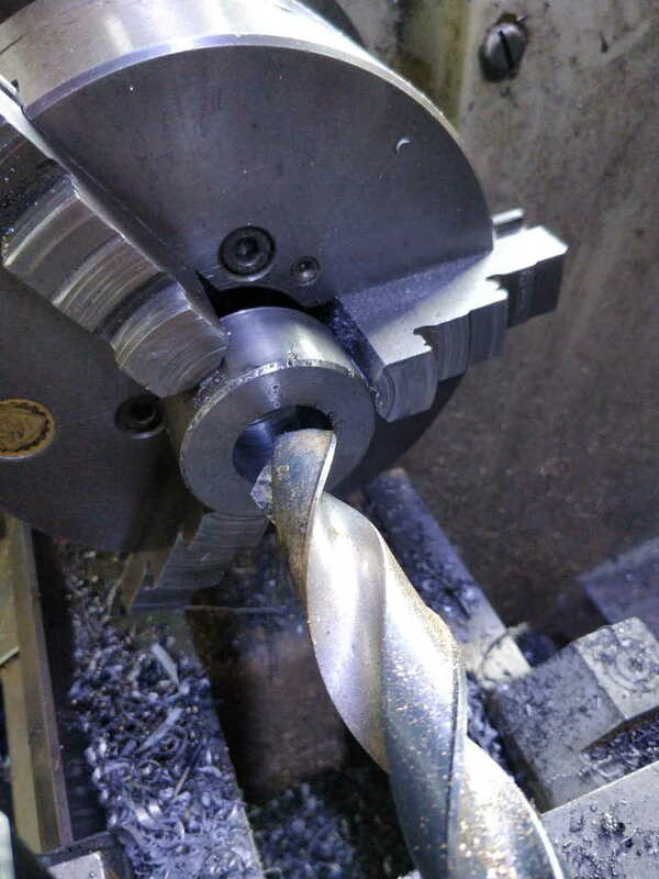
Then it was up through the drill bits as usual, stopping at 25 mm.
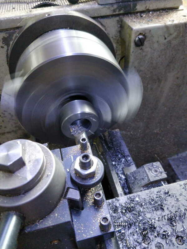
I then bored it out to be 30 mm, to fit the bits of tube I'm using in this project.
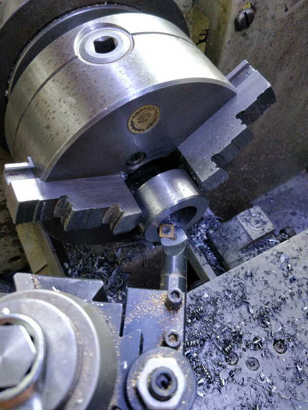
I moved the tool-post round to an angle and chamfered the ID under power for this one rather than using a deburring tool by hand. No particular reason.
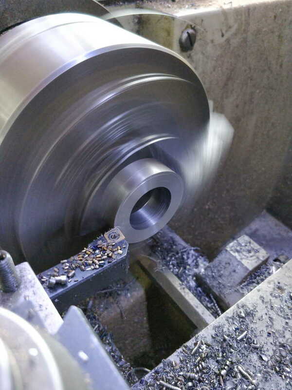
I then flipped the block over, faced it to length and chamfered the OD and ID on the other end as well.
I then fitted a cut-off bit of 50 mm EN1A into the chuck:
I faced the end, chamfered the corners and then spotted the centre hole.
Then it was up through the drill bits as usual, stopping at 25 mm.
I then bored it out to be 30 mm, to fit the bits of tube I'm using in this project.
I moved the tool-post round to an angle and chamfered the ID under power for this one rather than using a deburring tool by hand. No particular reason.
I then flipped the block over, faced it to length and chamfered the OD and ID on the other end as well.
Dr.Al
Old Oak
I then put the block in the milling vice and spot drilled four hole locations.
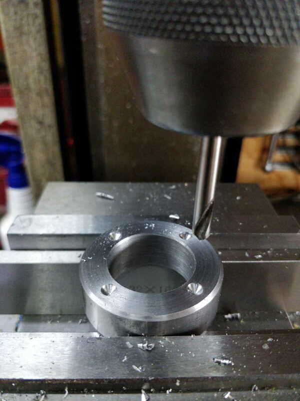
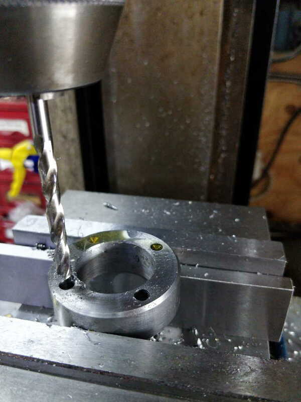
I then drilled the holes out 5.5 mm and counterbored 8.5 mm.
Here's the finished block. You'll notice that the counterbores are open into the central hole.
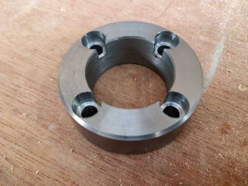
My original plan had been to mount four cap screws on the face of the central vice mechanism body (the one for the standard vice). Those cap screws were positioned such that the heads of the cap screws would retain the central tube and stop it from moving up and down. It then occurred to me that if I made it a more rigid connection, the tube that covers the central screw could act as a sort of "stretcher" to increase the rigidity of the structure (the two ends were originally designed to only be connected together by the rails at the top).
This block will be attached to the central tube, probably just with my favourite metal glue, Loctite 603, and will then screw into the vice mechanism joining the two ends together. I could add a cross screw to supplement the glue, but for now I'm going to assume it isn't necessary.
I then drilled the holes out 5.5 mm and counterbored 8.5 mm.
Here's the finished block. You'll notice that the counterbores are open into the central hole.
My original plan had been to mount four cap screws on the face of the central vice mechanism body (the one for the standard vice). Those cap screws were positioned such that the heads of the cap screws would retain the central tube and stop it from moving up and down. It then occurred to me that if I made it a more rigid connection, the tube that covers the central screw could act as a sort of "stretcher" to increase the rigidity of the structure (the two ends were originally designed to only be connected together by the rails at the top).
This block will be attached to the central tube, probably just with my favourite metal glue, Loctite 603, and will then screw into the vice mechanism joining the two ends together. I could add a cross screw to supplement the glue, but for now I'm going to assume it isn't necessary.
Dr.Al
Old Oak
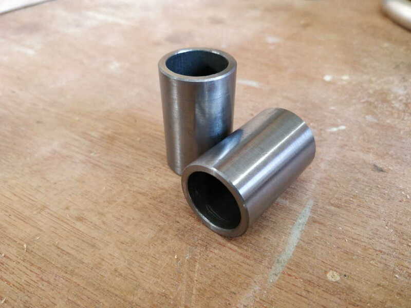
Next up was the tubes to run in the slotted bushes for the dual-screw vice. The original plan was to have these threaded onto the shafts, but I couldn't face another bit of 2.5 mm pitch thread cutting, so I just took a bit of the tube and skimmed the OD down to 25 mm to fit in the slotted bushes.
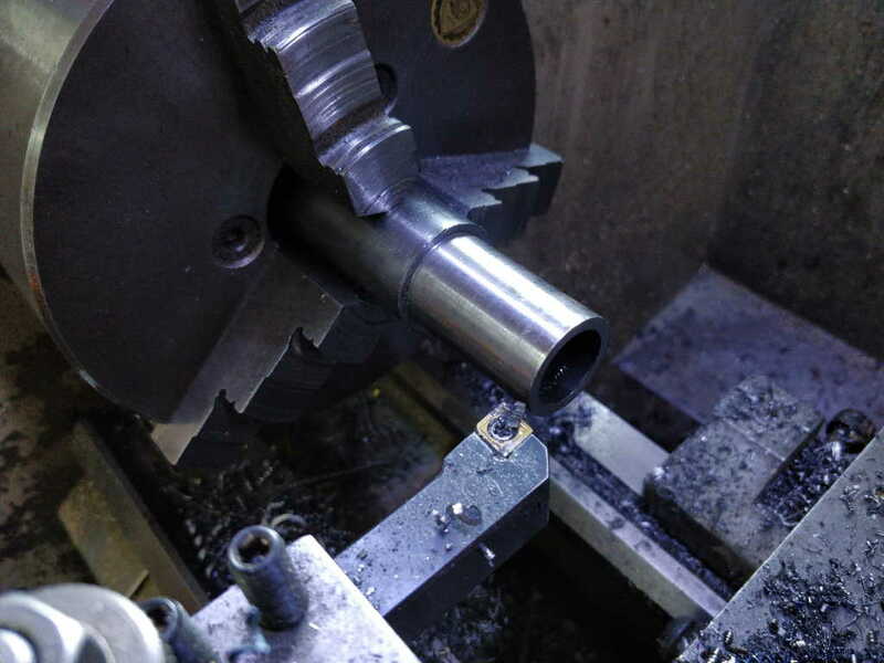
I then cut it off with the bandsaw, flipped it over, faced and chamfered and Robert's your father's brother:
My original plan with the holes in the wood for the slotted bushes was to rout them out once the brass bits were glued in place. However, I got impatient and wanted to do some trial fits before things got as permanent as being glued together. The brass bits are a close fit and are prevented from rotating by some dowel pins, so I figured it would be fine.
I fitted a top-bearing flush trim bit in the little router:
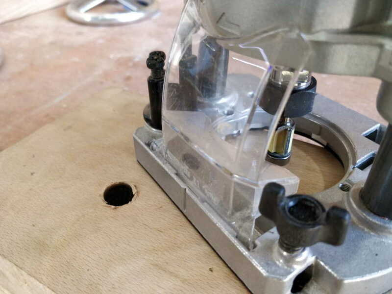
After very carefully setting the height so the cutter wouldn't cut brass, I worked steadily away at the holes until they were the same as the brass slot:
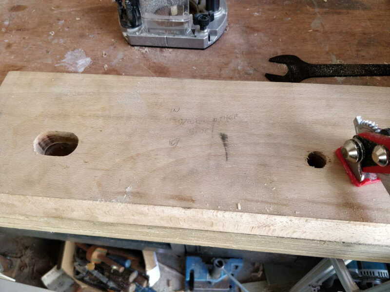
Something went slightly awry on the second hole - I think I wobbled a bit and lifted one side of the router up slightly. I don't think it matters though as it doesn't look horrendous and will be on the inside of the jaw.
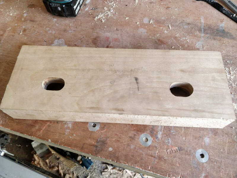
With all those bits complete I could do another test fit:
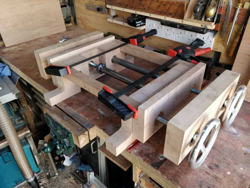
Here it is with the top slid into place as well:
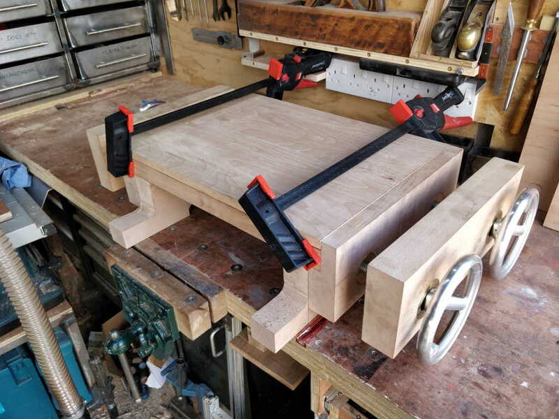
That brings us to a bit of a landmark: all the metal-mangling is complete (apart from whatever I decide to do about washers for the dual-screw end) and I can get back to some wood-worrying!
First job is to open up the slots for the vice mechanism bodies (to compensate for moving the shaft hole as I mentioned a while ago) and then I can do some functional tests.
I then cut it off with the bandsaw, flipped it over, faced and chamfered and Robert's your father's brother:
My original plan with the holes in the wood for the slotted bushes was to rout them out once the brass bits were glued in place. However, I got impatient and wanted to do some trial fits before things got as permanent as being glued together. The brass bits are a close fit and are prevented from rotating by some dowel pins, so I figured it would be fine.
I fitted a top-bearing flush trim bit in the little router:
After very carefully setting the height so the cutter wouldn't cut brass, I worked steadily away at the holes until they were the same as the brass slot:
Something went slightly awry on the second hole - I think I wobbled a bit and lifted one side of the router up slightly. I don't think it matters though as it doesn't look horrendous and will be on the inside of the jaw.
With all those bits complete I could do another test fit:
Here it is with the top slid into place as well:
That brings us to a bit of a landmark: all the metal-mangling is complete (apart from whatever I decide to do about washers for the dual-screw end) and I can get back to some wood-worrying!
First job is to open up the slots for the vice mechanism bodies (to compensate for moving the shaft hole as I mentioned a while ago) and then I can do some functional tests.
Dr.Al
Old Oak
Well, so much for "no more metalwork"... but more on that later.
This afternoon I started by working out how much extra space was needed for the vice mechanism. To do this, I fitted the vice mechanism to the fixed jaw and slid the foot up as far as it would go:
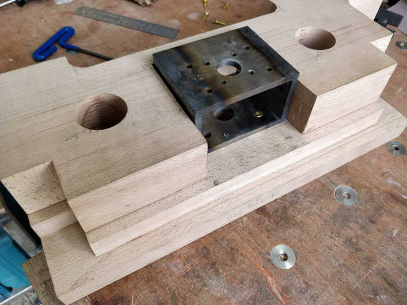
I could then measure how much the foot needed to move to get to the right place and therefore how much material to take away. Then I could mark it up and saw down the sides:
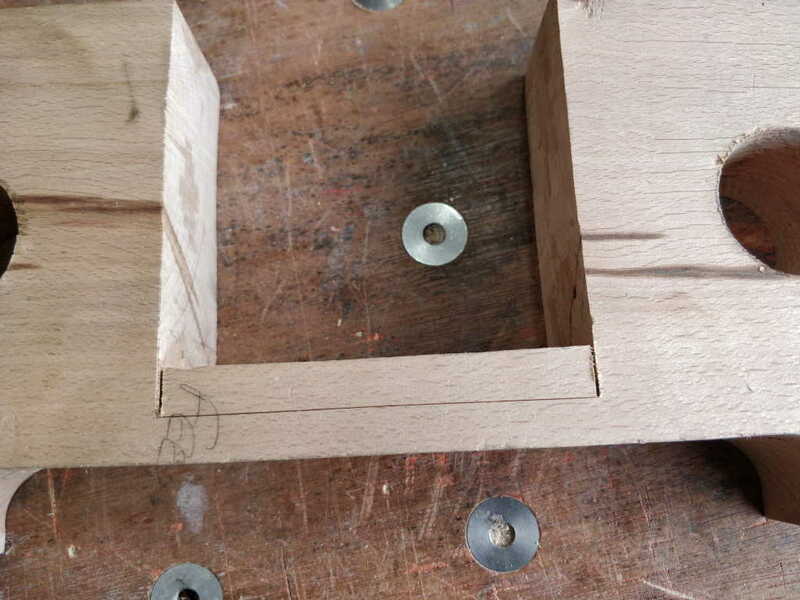
Chopping the material away was very quick as I was cutting along the grain:
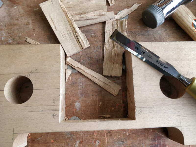
Finally, I pared the bottom down to make it a bit neater (although it'll be hidden under the vice mechanism so it's not too important how it looks):
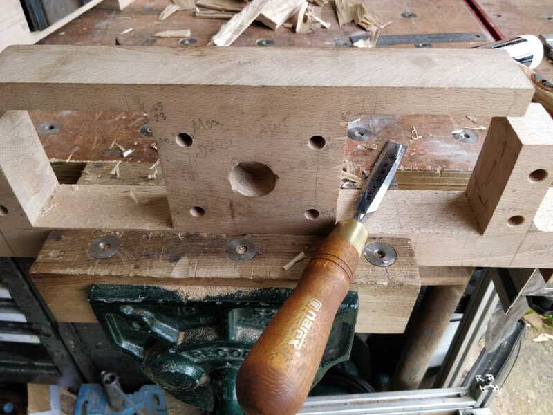
Having screwed the vice mechanisms to the fixed jaws, it seemed a good point to try one out with all the metal bushes / bearings etc in place. That's where I found that the vice mechanism didn't work. Lots and lots of profanity ensued.
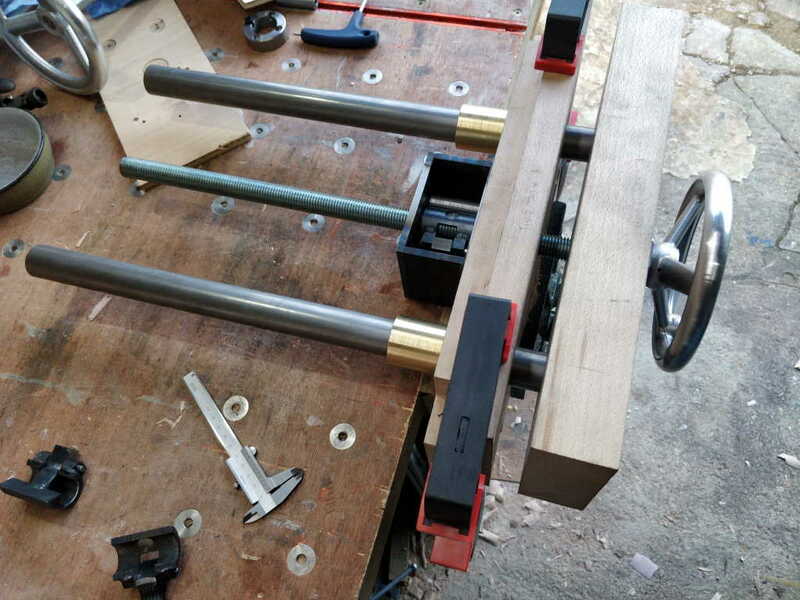
When I made the original vice mechanism prototype over Christmas, I did lots of testing to make sure it worked consistently and could be tightened very tight. When I modified the design to make it fit into a smaller space, I just checked it engaged and disengaged but didn't do any further testing. That was a mistake! What seemed to be happening was the geometry of the tube, the hinge bar location and the nut were such that as it tightened, the tube lifted off the threaded rod, which allowed the nut to drop away from the threaded rod.
After lots of messing around with various random scraps of material I had lying around, I worked out that all that was needed was something that would stop the tube from lifting when it was at the angle it sits when locking. I put one of the vice mechanisms back in the milling vice and drilled another 6 mm hole through both sides of the mechanism. I then turned a simple tube, 15 mm OD, 6 mm ID to sit on the new shaft and act as a stop.
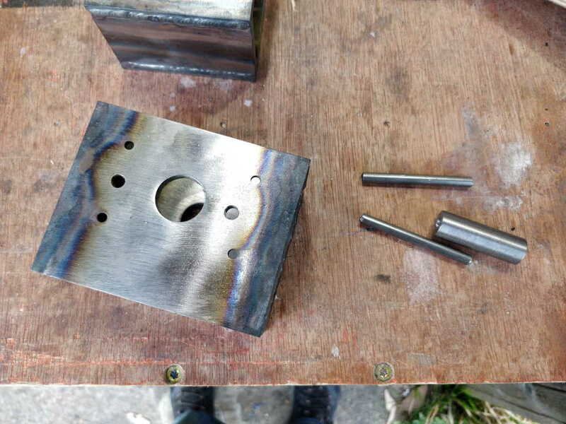
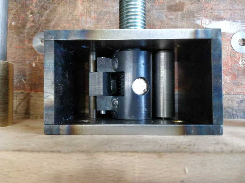
The reason I went with a 6 mm shaft with a separate part sitting on it was it gave me room to tweak the diameter if it didn't work. I'm glad I did as for some reason I can't quite work out, one of the mechanisms needed a 16 mm tube instead of a 15 mm one. I presume it must be something to do with the location of the hinge bar (which is arbitrary) as I'm fairly sure I drilled the hole in the right place!
With this modification, the vice is rock-solid and clamps bits of wood extremely robustly. Phew!
Anyway, with all the vice mechanisms modified and working well, I put the whole lot back together and clamped a random bit of wood in the dual-screw vice:
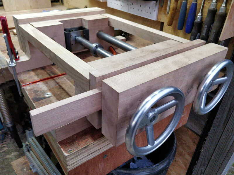
and cut the end off!

That was amazingly satisfying for such a simple job!
This isn't really the purpose of the dual-screw vice (I'd usually use the standard vice for this sort of cut), but I'd assembled it with that end facing out so I figured it would do.
If you look closely at those last two pictures, you'll notice that I've clamped one of the feet down to the workbench. It's a sign of the heft and hence stability of this thing that it didn't wobble at all, even though the end I was using wasn't attached (apart from via the screw threads going loosely through the holes in the rails for the other vice) to the bit that was clamped down.
I'm a much happier bunny now than I was when I realised it wasn't clamping properly!
This afternoon I started by working out how much extra space was needed for the vice mechanism. To do this, I fitted the vice mechanism to the fixed jaw and slid the foot up as far as it would go:
I could then measure how much the foot needed to move to get to the right place and therefore how much material to take away. Then I could mark it up and saw down the sides:
Chopping the material away was very quick as I was cutting along the grain:
Finally, I pared the bottom down to make it a bit neater (although it'll be hidden under the vice mechanism so it's not too important how it looks):
Having screwed the vice mechanisms to the fixed jaws, it seemed a good point to try one out with all the metal bushes / bearings etc in place. That's where I found that the vice mechanism didn't work. Lots and lots of profanity ensued.
When I made the original vice mechanism prototype over Christmas, I did lots of testing to make sure it worked consistently and could be tightened very tight. When I modified the design to make it fit into a smaller space, I just checked it engaged and disengaged but didn't do any further testing. That was a mistake! What seemed to be happening was the geometry of the tube, the hinge bar location and the nut were such that as it tightened, the tube lifted off the threaded rod, which allowed the nut to drop away from the threaded rod.
After lots of messing around with various random scraps of material I had lying around, I worked out that all that was needed was something that would stop the tube from lifting when it was at the angle it sits when locking. I put one of the vice mechanisms back in the milling vice and drilled another 6 mm hole through both sides of the mechanism. I then turned a simple tube, 15 mm OD, 6 mm ID to sit on the new shaft and act as a stop.
The reason I went with a 6 mm shaft with a separate part sitting on it was it gave me room to tweak the diameter if it didn't work. I'm glad I did as for some reason I can't quite work out, one of the mechanisms needed a 16 mm tube instead of a 15 mm one. I presume it must be something to do with the location of the hinge bar (which is arbitrary) as I'm fairly sure I drilled the hole in the right place!
With this modification, the vice is rock-solid and clamps bits of wood extremely robustly. Phew!
Anyway, with all the vice mechanisms modified and working well, I put the whole lot back together and clamped a random bit of wood in the dual-screw vice:
and cut the end off!
That was amazingly satisfying for such a simple job!
This isn't really the purpose of the dual-screw vice (I'd usually use the standard vice for this sort of cut), but I'd assembled it with that end facing out so I figured it would do.
If you look closely at those last two pictures, you'll notice that I've clamped one of the feet down to the workbench. It's a sign of the heft and hence stability of this thing that it didn't wobble at all, even though the end I was using wasn't attached (apart from via the screw threads going loosely through the holes in the rails for the other vice) to the bit that was clamped down.
I'm a much happier bunny now than I was when I realised it wasn't clamping properly!
NickM
Old Oak
This is super impressive.
Dr.Al
Old Oak
What with it being a work day again I didn't get much time today, but I did manage a little.
I took everything apart again and ran round a few of the edges (outside of the moving jaws and the edges of the feet) with a 6 mm Arris bit in my small router.
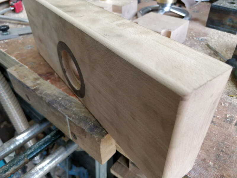
I then got some 120 grit sandpaper and gave everything a once over. For some strange reason, I elected to do this by hand rather than using any power tools. I don't know what came over me!
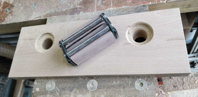
I'd been debating what to do about the feet as I wanted to round over the corners of the feet but it would look a bit odd if it blended into the hard edge of the fixed jaw. Without the rounded edge, I needed to do some adjustment to either the fixed jaw or the feet to either make them line up perfectly or make them look deliberately not aligned.
After playing around in the CAD model, I took the plunge and went round all the outside edges of the feet; hopefully it'll look okay when assembled having a rounded edge on a join.
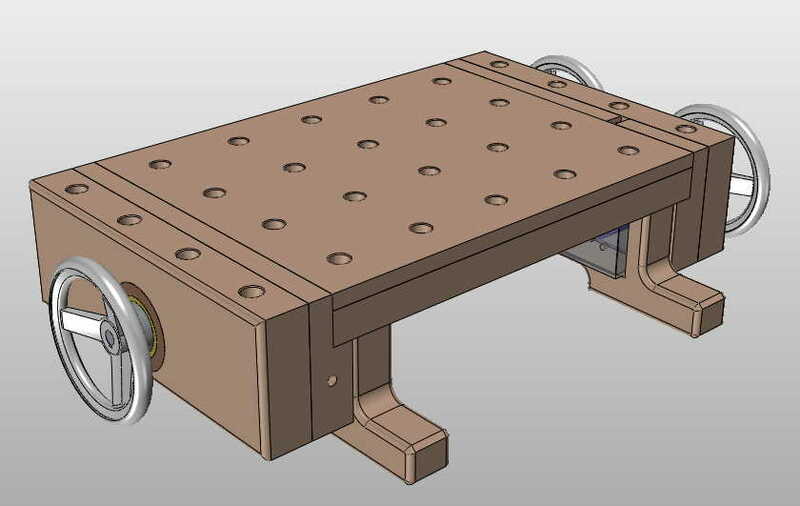
You can (hopefully) see the where the rounded edge of the foot meets the square edge of the fixed jaw in the latest version of the CAD model:
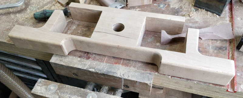
Here's what one of the feet looks like after shaping and sanding to 120 grit. I'm definitely not going for perfection here: it is first and foremost a tool rather than something that has to look pretty.
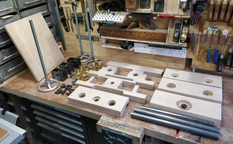
While everything was apart, I took some photos of all the bits I've made so far:
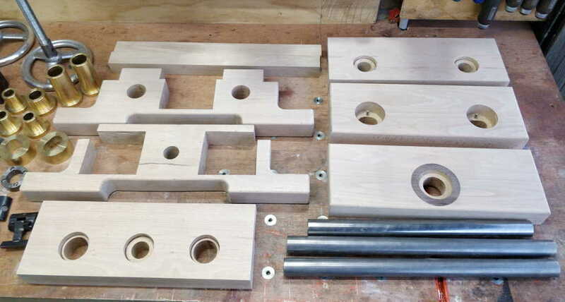
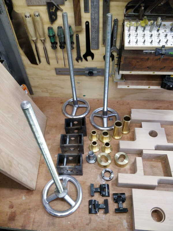
I took everything apart again and ran round a few of the edges (outside of the moving jaws and the edges of the feet) with a 6 mm Arris bit in my small router.
I then got some 120 grit sandpaper and gave everything a once over. For some strange reason, I elected to do this by hand rather than using any power tools. I don't know what came over me!
I'd been debating what to do about the feet as I wanted to round over the corners of the feet but it would look a bit odd if it blended into the hard edge of the fixed jaw. Without the rounded edge, I needed to do some adjustment to either the fixed jaw or the feet to either make them line up perfectly or make them look deliberately not aligned.
After playing around in the CAD model, I took the plunge and went round all the outside edges of the feet; hopefully it'll look okay when assembled having a rounded edge on a join.
You can (hopefully) see the where the rounded edge of the foot meets the square edge of the fixed jaw in the latest version of the CAD model:
Here's what one of the feet looks like after shaping and sanding to 120 grit. I'm definitely not going for perfection here: it is first and foremost a tool rather than something that has to look pretty.
While everything was apart, I took some photos of all the bits I've made so far:
Dr.Al
Old Oak
Question to the floor: what do you think I should do in terms of finish (both in terms of what grit to sand to and what, if anything, to put on the wood)?
My logic thus far is that it'll probably be more grippy for clamping things without any finish, but it'll probably look awful fairly quickly.
Most of the reason I had to do sanding today (rather than leaving the planed finish) was because of grubby fingerprints from going back and forth between the oily metalwork area of my workshop and the wood area. Having some sort of finish that stops cutting oil on my hands from soaking in seems a good thing. Danish oil would be my preferred option for minimum effort (it doesn't seem worth mixing up some of Mike's Magical Mix for a bit of workshop equipment), but am I going to regret that?
I'm also conscious that Danish Oil will probably show up all the imperfections in the surface (especially in the feet, which have a lot of imperfections) unless I do a LOT more sanding!
My plan with the standard vice jaws is to put some leather on the inside of the jaws (with contact adhesive if I can't think of anything less horrible to use) as I figure it'll grip things well without marring. The dual-screw jaws will be left without leather though.
I'd welcome any and all opinions!
My logic thus far is that it'll probably be more grippy for clamping things without any finish, but it'll probably look awful fairly quickly.
Most of the reason I had to do sanding today (rather than leaving the planed finish) was because of grubby fingerprints from going back and forth between the oily metalwork area of my workshop and the wood area. Having some sort of finish that stops cutting oil on my hands from soaking in seems a good thing. Danish oil would be my preferred option for minimum effort (it doesn't seem worth mixing up some of Mike's Magical Mix for a bit of workshop equipment), but am I going to regret that?
I'm also conscious that Danish Oil will probably show up all the imperfections in the surface (especially in the feet, which have a lot of imperfections) unless I do a LOT more sanding!
My plan with the standard vice jaws is to put some leather on the inside of the jaws (with contact adhesive if I can't think of anything less horrible to use) as I figure it'll grip things well without marring. The dual-screw jaws will be left without leather though.
I'd welcome any and all opinions!