• Hi all and welcome to TheWoodHaven2 brought into the 21st Century, kicking and screaming! We all have Alasdair to thank for the vast bulk of the heavy lifting to get us here, no more so than me because he's taken away a huge burden of responsibility from my shoulders and brought us to this new shiny home, with all your previous content (hopefully) still intact! Please peruse and feed back. There is still plenty to do, like changing the colour scheme, adding the banner graphic, tweaking the odd setting here and there so I have added a new thread in the 'Technical Issues, Bugs and Feature Requests' forum for you to add any issues you find, any missing settings or just anything you'd like to see added/removed from the feature set that Xenforo offers. We will get to everything over the coming weeks so please be patient, but add anything at all to the thread I mention above and we promise to get to them over the next few days/weeks/months. In the meantime, please enjoy!

Remote start up and three phase

Jimmy Mack

Old Oak
Joined
Mar 21, 2016
Messages
1,093
Reaction score
0
Location
Leeds, West Yorkshire
I'm looking at switching my start/stop on my 3ph extractor for a DOL... So I can put in a single phase remote....3 pole contactor with 240v coil

Looking at the motor connection/ terminal panel it (the motor) has four wires, when I was expecting three, L1,L2 &L3....(& gnd of course)... My feed up to the existing (sealed) start /stop is L1, L2, L3 (&gnd) ... Tho the other side of this sealed start/stop is producing a four wire connection. Is this some kind of balance?

Jim [emoji848]


Sent from my Moto G (5) using Tapatalk
 
So the extra wire is connected to the delta point at the motor end?

Trace the other end of that wire to find what it does. Possibly nothing or just maybe there is some need for a local neutral. Is there an agitator motor to rattle the filter perhaps?
More info needed

Bob
 
Hi Bob,

No filter agitator or anything, just a plain old fan.

I'll try and get inside... In the meantime a few pics...

Rotary isolator, standard stuff... Three lines in, three out to the starter on the clear Flexi swa
b7161e175ef8aa57a092ffe25590ef1b.jpg


Three lines into my starter, which appears to be sealed, even behind the label I can't see a way in [emoji848]
ee4153d3076459ae3b93bae128a0cd90.jpg
f10fbd899438e52c8c2d9204dbe96443.jpg


And the fan motor terminals, receiving four from the starter

74270ea6386780f36796d733b689fef1.jpg
d30b6e7f091aeee36de622e11a06b2e6.jpg


I've had a look over the motor for a spec plate, but no further info

Jim

Sent from my Moto G (5) using Tapatalk
 
Given there are no other bells and whistles on the machine, then I suspect the fourth wire is a normally closed thermal switch connected to one of the phases inside the motor. If the motor gets hot the switch opens and acts on the nvr coils to turn off the supply.
Theses thremal switches only operate at low current and therefor it is vital that we find which of the four wires are the three high current phases and which is the low current thermal switch.
This cannot be done by simple voltage measurements alone
You are going to have to do some investigation. Do you have a multimeter (DVM) capable of measuring ac current to say 10 amps and know how to use it?
Maybe post a photo of your meter?

Bob
 
Ah right, I see, is it a (cheaper) similar intention as having a thermal overload relay, to detect high continued current draw, failing fielding/ winding, too high load etc?

Or a thermostatic switch for overrunning or fan air flow/ cooling restriction?

My brother has the multimeter, I'll have him bring it over.

Sent from my Moto G (5) using Tapatalk
 
Jimmy Mack":1mi0izo6 said:
Ah right, I see, is it a (cheaper) similar intention as having a thermal overload relay, to detect high continued current draw, failing fielding/ winding, too high load etc?

Or a thermostatic switch for overrunning or fan air flow/ cooling restriction?

My brother has the multimeter, I'll have him bring it over.

Sent from my Moto G (5) using Tapatalk

Yes this method which measures elevated temperature once the motor has got hot rather than checking the current draw as is done in a proper DOL starter. It is the cheap and nasty companion to the nasty NVRs that are creeping in on chinese sourced machines.
In your proposed new solution I suggest that you use a proper DOL starter as the starting point for your remote control and you will get decent protection.

I will draw a diagram later to show how to make the measurements to show which wire is the thermal switch. Normally black, brown and grey will be the high current wires leaving blue for the switch but we need to confirm this properly.

Cheers
Bob
 
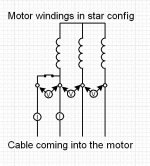
ok here is the diagram of what I expect is in your motor.

Motor1.jpg
you will be making measurements on running equipment at three phase voltages.
These will bite! take great care!
Method:
Set meter to measure >500 v ac.
Start the machine
Probe between each of the 4 incoming cables.
Most will read 400v but just one pair will be virtually zero volts
This pair will be the thermal switch
Call these A and B
Configure the meter to read 10amps AC (NOT DC)
Stop the machine and make permanent connections to the meter in series with point A.
Start the machine and record the steady current.
Stop the machine replace the connection to A and insert meter in the lead to B.
Start the machine and record the steady current.
The lead that has virtually no current flowing will be the temp sensor. You wont need this in the new scheme. Cut the wire off from the imcoming cable.
The other three will be the high current feeds to the motor.

Use just these three to your new DOL switch

Bob
 
Thank you Bob for taking the time to write this up, I'll try this soon.

Is the second test to record the current draw... Essentially belt and braces, confirmation?

Jim

Sent from my Moto G (5) using Tapatalk
 
Jimmy Mack":16txtm6o said:
Thank you Bob for taking the time to write this up, I'll try this soon.

Is the second test to record the current draw... Essentially belt and braces, confirmation?

Jim

Sent from my Moto G (5) using Tapatalk
Its not belt and braces, you need to find which wire of the pair is carrying the motor current, as you need that one connected, while the other 'sence' wire will be disconnected.
 
9fingers":2p70iad3 said:
yup Wot he said!
thanks Dave

Bob

:cry: It was getting late.

Ok, here we go...


My A&B

AB.jpg

Running Flow & Full Load Amps

ASU.jpgA.jpgBSU.jpgB.jpg


'A' is my sensor then, shall I just disconnect it and put it on a blank terminal block ?


Jim
 
HI Jim,

When you are ready to fit the new remote switching system leave the A wire connected to the exisiting terminal block at the motor end and put a little note in the box saying what it is for the future.

Then when wiring up the new switch snip off the A wire in the cable in the box leaving 3 wires plus earth used.

Similarly snip off the a wire at the far end of the motor cable.

Bob
 
Thanks Bob, and thanks for helping with the diagnostics [emoji16]

I'll have a look into the switch next week, before I isolate the thermal sensor.

My plan is to connect a 240v remote to a 3 pole contractor with a 240v coil.... Doesnt look like Toolstation can help this time, though I might use the old/ new Toolstation DOL box* to house a contactor I've seen in Screwfix... Along with a thermal relay.

How do I calculate the required cut out Ampage... It must be somewhere around 5.5 - 6A?

(*Contractor pinched to fix Planer thickness)


Jim

Sent from my Moto G (5) using Tapatalk
 
Jimmy Mack":2ueet186 said:
Thanks Bob, and thanks for helping with the diagnostics [emoji16]

I'll have a look into the switch next week, before I isolate the thermal sensor.

My plan is to connect a 240v remote to a 3 pole contractor with a 240v coil.... Doesnt look like Toolstation can help this time, though I might use the old/ new Toolstation DOL box* to house a contactor I've seen in Screwfix... Along with a thermal relay.

How do I calculate the required cut out Ampage... It must be somewhere around 5.5 - 6A?

(*Contractor pinched to fix Planer thickness)


Jim

Sent from my Moto G (5) using Tapatalk

The tool satan one will do what you want just select 240v coil. All their contactors are three pole and rated for three phase voltages.

95364 plus 89114 should do nicely

Bob
 
I've Google found a PDF manual for the extractor! ....And in it is a schematic :eusa-doh: , see below! I don't know why I didn't do this before. Though it's been a useful exercise me.

The reason for the manual search was to try and get some info on the motor rating ( no spec plate) to calculate the required thermal overload. Looking at some websites I'm getting a little confused by the maths involved :? .

Is there a rule of thumb? Perhaps 10% over the Running Ampage of a line and allowing for 50% on another line behind? Based on one of my lines being 3amp (max running ampage read ), would a sensible cutout setting be 5 amps?

The motor is 2.9KW 50Hz

There are some details on the switch, though I'm not sure if they are specific to the motor and switch or just the switch itself.


Apologies if these are rather simple questions

Screen Shot 2019-03-24 at 09.42.07.png

ee4153d3076459ae3b93bae128a0cd90.jpg
 
I'd not realised that it would have such a beefy motor. the low running current confused me. :oops:
2.9kw is almost 4 hp.

Thermal overload relay should be set for the full load current and ideally that should sit in the middle of the adjustment range but this is not always possible depending on what is available.

Full load current on a three phase 400 v star motor is around 1.7 amps per hp (2.3amps per kW) so 6.5-7amps for your motor.
Your measured figure was quite a bit less I think and this could well be to do with lower friction in your ducting compared to the maximum the extractor is designed for.

The thermal relay is there to protect the motor and the motor should be happy with drawing 6.5-7 amps so I'd go for the 31837 relay 5-8amps. Set it at minimum for now and be prepared to tweak it up a bit if you are getting nuisance trips.

hth
Bob

HTH
 
Thanks Bob, I almost opted for the lower rated relay. Knowing that my 3.3kw Sedgwick planer cut out is set to 6.5A (ref manual) thinking that it, the PT will likely experience higher loads than the extractor fan... Though if all my extraction gates are closed maybe not.

To be fair the manual (see pic) isn't helpful as it also lists the motor at 3hp, so I went with the higher Kw rating.... So perhaps it is 3hp and the Kw are wrong? [emoji848] ... (Regarding your original thoughts on it's size and current pull, tho this could also be the low load of the fan)

The physical appearance of the motor *is* rather large. Though this is probably a poor indicator.

Thanks again,

Jim
ea218d67aec8acb7df3751d6185afb13.jpg


Edit. Ps...my machine is column, far right

Sent from my Moto G (5) using Tapatalk
 
P1 is the input power and P2 the output power.

Note that the difference is not implying huge inefficiency in the motor but a mix of some waste heat output and power factor.

My 1.7 amps pwer hp is a figure to cover both rating ie an input current for an output horsepower.

So your full load current will be in the region of 5.1 amps and so use the next lower thermal overload that I first suggested. Furthermore it makes your running current measurement more likely too.

Bob
 
Looks the part Jim!

Just as a check, you did remember to wire the coil in series with the output contacts on the thermal overload relay?

I only mention it because many people think the overload relay it self contains switches to disconnect the load.

This is not the case. It contains current sensors that open an isolated contact pair when over current is detected.

Cheers
Bob
 
9fingers":2rhufhry said:
Jimmy Mack":2rhufhry said:
My coil supply comes in at 96 and out of 95 (down left hand side) to A2

Sent from my Moto G (5) using Tapatalk

That is Spot On Jim exactly as it should be. We will make a sparky of you yet! [emoji38] [emoji38]

Bob
Woo!!!! [emoji41] Time for a proper job! [emoji16]


From checking continuity...I'm assuming the pair on the left are for sounding an alarm or lighting a warning lamp, be as they appear to be normally open and close on trip.

Sent from my Moto G (5) using Tapatalk
 
Jimmy Mack":hrajbghz said:
From checking continuity...I'm assuming the pair on the left are for sounding an alarm or lighting a warning lamp, be as they appear to be normally open and close on trip.

Sent from my Moto G (5) using Tapatalk

Spot on again. I can see I'm becoming redundant round here :lol:

Bob
 
9fingers":pv3uegoz said:
Jimmy Mack":pv3uegoz said:
From checking continuity...I'm assuming the pair on the left are for sounding an alarm or lighting a warning lamp, be as they appear to be normally open and close on trip.

Sent from my Moto G (5) using Tapatalk

Spot on again. I can see I'm becoming redundant round here [emoji38]

Bob
I doubt it [emoji38]...

I've learnt quite a lot from this thread/ project and about motor control in the past year, saving myself £100's.

This switch is a great addition to the workshop, something I've be thinking about for over two years... Can't believe I've been in here that long!

Cheers, Jim

Sent from my Moto G (5) using Tapatalk
 
Back
Top