• Hi all and welcome to TheWoodHaven2 brought into the 21st Century, kicking and screaming! We all have Alasdair to thank for the vast bulk of the heavy lifting to get us here, no more so than me because he's taken away a huge burden of responsibility from my shoulders and brought us to this new shiny home, with all your previous content (hopefully) still intact! Please peruse and feed back. There is still plenty to do, like changing the colour scheme, adding the banner graphic, tweaking the odd setting here and there so I have added a new thread in the 'Technical Issues, Bugs and Feature Requests' forum for you to add any issues you find, any missing settings or just anything you'd like to see added/removed from the feature set that Xenforo offers. We will get to everything over the coming weeks so please be patient, but add anything at all to the thread I mention above and we promise to get to them over the next few days/weeks/months. In the meantime, please enjoy!

Router table insert plate build (rings laad)

TomTrees

Sapling
Joined
Aug 19, 2014
Messages
380
Reaction score
98
Hello folks, will have to excuse the lack of pics, but sure I can bump this up later with some.
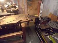
Making a router insert plate for a tablesaw extension wing at the moment...
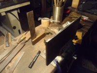
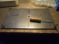
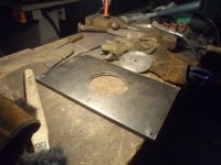
SAM_9055.JPGI've only marked out the rounded corners on this 8mm steel plate, but not shaped them yet,
as I've kept the sharp edges for twofold, (justabout)
One possible merit what's a stretch, being for better stability when countersinking holes,
The reason being though, is getting a 3/4" radius on the corners when routing,
I'm thinking this may be a slight aid, should I have to make up a jig.

The jig being the issue?.. as in whether there's a clever solution to getting such a profile without the use of special bearing guided
bits, as everything I've seen has been either that or some bush guided system.
Neither of which I own, (I'm doubtful those liddle ones could do the trick)
and not being familiar with them, or should I say not being familiar with possible DIY solutions if any,
not willing to go there without seeing anything like that first,
or indeed unsure if there's other methods more cleverer for this one time deal for likely a long time,kinda thing.

The material is 1" thick, so I want a flat bottomed hole for threaded inserts, and it's really really horrible stuff to work,
so I'm looking for better than nibbling a pecked 19mm bit to the radius.
(Not sure if I've got a hole saw the right size, should that work on a test piece)

Love to see some solutions, should anyone be able to suggest something.
Cheers


All the best
Tom
 
Last edited:
I can’t help because I don’t understand the question!"
Hi Mike, I'm wishing to find out a possible technique to rout out a recess for the steel insert plate to sit in.
SAM_9075.JPG

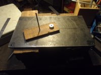
As of yet, just drilled a 1/2" hole drilled for centering up a bit,
and using some machined half inch bar which will maintain alignment for marking out.
(not ground the 3/4" roundover on the steel plate yet)
SAM_9081.JPG
The methods I've seen for routing the recess, all involve a pattern bit of some sort,
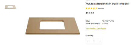
and making a female template to guide a specific bit which will result in the corners having the 3/4" radius I'm after.Screenshot-2024-7-1 AUKTools Router Insert Plate Template Wood Workers Workshop.png
This plate will be sitting on a ledge, routed say.. 1mm lower than the plate, as there will be leveling screws
as well as four ones which will affix the plate to the tablesaw wing, on each corner with brass threaded inserts,
hence not as simple a job as it may seem... well not without the bit in question.
I only have a box of 1/4" Parksides and other straight cutters on larger routers, and no router bushings either.

Can the job be done well without, using some old school method,
or might the job be best done in lieu of such toolery, using a hole saw to achieve the radius?

Cheers
Tom
 
I bought the matching template when I bought my Incra plate from WW'sW, together with Peter's stainless insert to sit on said ledge, to stop the grub screws sinking into the softer MDF of a table. I thought at one point I wouldn't need the template, but I did, for a tiny adjustment to the depth on my Incra tabletop (to allow for the SS insert).

The template worked very well indeed.
 
I bought the matching template when I bought my Incra plate from WW'sW, together with Peter's stainless insert to sit on said ledge, to stop the grub screws sinking into the softer MDF of a table. I thought at one point I wouldn't need the template, but I did, for a tiny adjustment to the depth on my Incra tabletop (to allow for the SS insert).

The template worked very well indeed.
That might be a better option with the grub screws, but numpty as I am, ended up thinking I had accounted
for enough, and found I had to make the plate a little narrower than planned.
I didn't reckon at the time I'd be wanting a hole about 97mm until I checked it,
as that leaves not quite as much meat either side of the router as I'd like.
So it looks like I'll be using my slightly fancy threaded inserts on the black stuff, in order not to weaken the plate,
which has to suspend the weight of a big ol Elu router.
No funds for router bits yet, though I'd be interesting to see what bit or indeed bushing you used in conjunction with the jig.

(p.s, I've only got a regular half inch bits or quarter inch bits at the moment.)
SAM_9044.JPG

Cheers
Tom
 
Last edited:
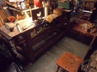
I'm not precisely sure what you want to do Tom but the starting point in the following method of cutting the opening for a router plate is the radius of the router cutter you choose to use because it determines the radius of the corner in the table opening and consequently the radius of the corner on your plate
It's not too hard to make up a template using say good quality (dense enough not to splinter) 12mm ply - don't skimp on the size of the piece. (leave room to get the router around the required opening without catching the clamps - see below)
Tack or screw x4 decent width guide strips of straight edged ply to the back of your intended template positioned to precisely outline the rectangular opening you require.
It might be easiest to do this by laying your steel plate (making sure to get it right way up because it might not be exactly square) on the back of the ply and butting the strips tight up against it. I sometimes wick dabs of low viscosity (watery) superglue (spray the surfaces first with activator as supplied with the various mitre bond kits) under the strips to tack them in place before screwing or tacking.
Drill a hole to get started and remove most of the material from the centre with a jigsaw. (don't go too close to the required line as they cause splintering even with a fine toothed blade)
Select a bottom bearing guided profiling router bit of the required diameter to run on the guide strips you have just attached, and run it around the opening so that it trims flush to the edges of the guide pieces. You'll end up with a template with nice round corners which exactly matches your steel plate.
Once this is done knock off the guide strips and sand off any lumps of super glue.
It's a good idea to glue and screw an accurately positioned fence to templates like these to pick up on a handy reference edge of your workpiece.
Clamp it down tight and rout the step surrounding the opening in your table.. (you will need an end cutting/planing top bearing guided cutter this time)
On rounding the corners of the plate to fit the corners of the opening.
Failing access to a CNC mill it's possibly most practical to mark the radius using a washer and a sharp scriber (blue the steel first with a permanent felt pen), clip the excess off with cutting disc in an angle grinders, remark if the heat has disappeared your original marking and finish with a good file. (the box store variety are made of cheese and don't cut) A linishing (metal sanding) belt with a table would make this finishing easier if you can get access to one.
A thought on support/levelling screws.
Your plate needs to be accurately flat.
If you're confident in the strength/stiffness of the plate any more than four screws just makes life awkward when levelling the plate.
Screw one down out of the way, level accurately using the remaining three and then carefully raise the fourth until it just contacts the plate.
Trying to level four or more at once gets frustrating.
If you're using socket head screws for levelling maybe think of drilling holes in the plate centred above each screw so that you can adjust the screws with the plate in place.
Maybe even mark and drill the holes accurately in the plate first, then use it as a template to drill through into the table for the screws - or at least mark the centres using a hand held brad point drill.
Steel threaded inserts epoxied into the table for the levelling screws would be a nice touch, but they can be a bitch to get accurately centred and vertical. The trick is to drill the hole for them only a little smaller than their outside diameter - the epoxy will fill the gaps. Mount them on say a 150mm length of threaded rod against a couple of nuts locked together, coat the hole and the insert with epoxy (a slow curing one makes life a lot more relaxed) and run them in using a power driver at low speed.

Good luck with it..
 
Last edited:
Looking more and more like I'll have to do it the hard way, and I've still got to see if I've got a suitable holesaw.
Not being sure what this material is, as it's a composite of sorts, which is quite dense, seemingly a lot more in hardness to
other plastics I've worked, something more like bone I suppose.
Not tried using a hole saw on the stuff, should I have one, and will need to do a test cut beforehand.
Much the same deal as with routing, as I've not tried that either.

No rush on things regarding my query, as I've got to drill out the plate and figure out a ledge for the inserts yet.
and make those too, so not going to be stuck procrastinating about that yet.

Edit, suppose yer all wondering why I don't go out and buy a bit like this one, what's seemingly the cheapest available
but I was eager to get a bit for me 1/2" router, so I could use that in the table.
Screenshot-2024-7-1 Erbauer 1 4 Shank Double-Flute Straight Router Cutter 12 7mm x 19mm - Scre...png

Cheers
Tom
 
Last edited:
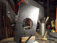
Went out and checked what size bits I had, just to see if I was lucky one of the bits from liddles,
or indeed the straight cutter in the medium sized router might be 18mm, but the closest in size is
16mm in the box.
Whilst digging out that router, I did however find some sort of bush for it, but the cutter is only about 12mm for that.

No luck either with the holesaw, now wishing I didn't pilot the four holes for the screws, :(
as I guess a radius of 16mm might not look too awful.

SAM_9092.JPG

Perhaps it could be bodgable, in hindsight I'm glad I didn't mark out the roundover on both sides...
so must dig for the right sized 16mm washer and see how it looks.

Plenty of work to do in the meanwhile, so I'll be leaving that off for a while.
Might as well show a few more photos of things
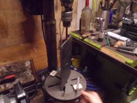
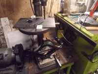
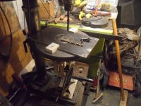
Had to disassemble my lateral stop to utilize the drill for tramming purposes

The jack will be going back on for the next job, as it's very nice to have for times when no vice is large enoughSAM_9083.JPG

i.e SAM_9066.JPG
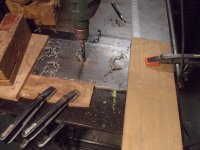
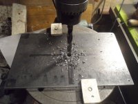
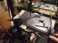
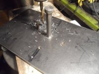
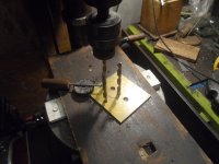
Ignoring the chips from the only half inch bit I've got, you can see I've got no worries about knowing the drill will be centered
on the table, i.e smack in the middle of the hole in the table, so can drill holes up to quite a large size like such.
SAM_9070.JPG

Marked out and pecked the holes for mounting the router
SAM_9089.JPG
Now to figure some sort of indexing jig for the big hole in the plate, which will be interesting to try and do well.

Cheers
Tom
 
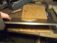
Found a 16mm washer, and marked out the underside to see if it looked OK...
Seems I might be able to get away with a bit of filing those holes without them becoming overly enlarged...
not sure yet.
SAM_9096.JPG
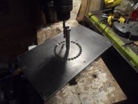
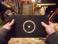
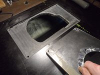
Made a start on the big ole

SAM_9098.JPG
Not a great setup, as I was only messing about really
SAM_9099.JPG

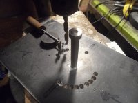
This could be done a lot better, there's surely a trick which I haven't sussed yet involving getting the first three holes the same distance apart, so the rest becomes plain sailing.
I didn't do this, and plonked away at it, which made work for myself.

Thinking about it, if I'd drilled two holes into a bit of plate of the preferred spacing.... then that's how to get the spacing right for the first holes! :sleep:


No point in figuring out getting everything symmetrical, as it will upset things....
unless yer some CAD guru who can figure out the spacing easily, with whatever bit you choose.
SAM_9111.JPG
You need clean out the hole everytime like so
SAM_9114.JPG

That turned out great considering my numptiness, probably could'a used a smaller drill, next time perhaps.SAM_9115.JPG
Happy enough with that for now.

Cheerio
Tom
 
Last edited:
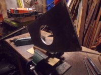
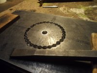
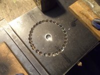
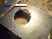
Just about finished tidying up the hole.
I'd love to know what this makers mark is...anybody?
SAM_9119.JPG

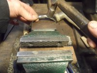
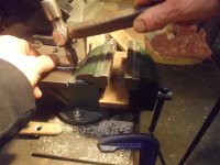
That's after four thumps IIRC
SAM_9121.JPG

Turned over and repeated
SAM_9128.JPG

Started with a triangular file
SAM_9129.JPG

Needed to do some essential Feng Shui for comfort to proceed
SAM_9131.JPG

I'd say I only got lucky that I didn't go beyond the line when drilling, you never know until the burr releases as when close,
the line becomes hidden.
I should have marked it deeper on the underside.
SAM_9133.JPG

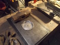
Pretty much done, just a few rubs left to do.
Getting closer to mucking around with some pipe perhaps, not sure yet.
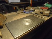
SAM_9137.JPG

Cheerio
Tom
 
That's heavy work done manually Tom.
Full marks...
 
Makers mark Tom?
Andy
I was referring to the cold chisel Andy, if indeed that's what it's called.
Perhaps it might have some other term. should it be intended for stonemasons, blacksmiths or another craftsperson?
SAM_9140.JPG

@vaj Cheers, hoping the rest of the work goes as smoothly.
All the best
Tom
 
Not one I know off the top of my head Tom, looks European, @AndyT may be more enlightened?
Cheers, Andy
And there I was, keeping quiet, thinking you'd know Andy...

But following your hint that it looks European, my response is, as ever, to hop over to the ever-useful old tool museum/ reference site of Wolfgang Jordan. He has a handy database of trade marks, and by searching for "hammer" (in English!) I found two possible sources.

Julius Etzold

etzold_logo.jpg


or Robert Frohn

frohn_markenanmeldung_1895.jpg


which looks more likely to me.

Hope this helps!
 
Thanks Andy, how you managed to find that, never heard of Robert Frohn before.
I must give the stamp another bit of a rub to see if the hammer is still the same shape, just to see if that might
give some more clues as to whether the name might have changed hands, since I don't see any other chisels
from a quick google.

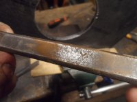
I can't say this tool is superior to anything similar, as I've not compared, but my impression is this steel is a bit special,
as I didn't think this sorta thing was possible to do. (without needing to grind afterwards)
I've chopped bigger welds than that since, and thought I'd better pictures of it.

Be interesting to see if it's the tool, or if it's the steel which obliges to this malarkey.
SAM_8618.JPG

All the best
Tom
 
Just a little update on things so far, not got much done since as the weathers been good.
You might note the marker used to ensure I don't go beyond the line at the far end of the cut
SAM_9147.JPG
Which leaves a little "tenting" to be removed... which I can't say I done satisfactory trying various things on the fly,
like an old bearing scraper used the same, it seems a wee tool needs to be made for this job, which I may have to make yet,
but got the opening good enough to continue for now
SAM_9175.JPG

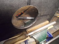
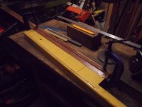
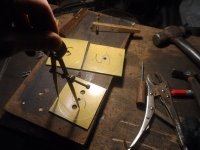
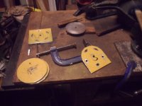
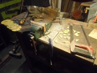
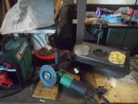
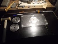
Made a start on the rings, don't know why I haven't been clamping a batten for doing the job,
as it makes outside cutting much more pleasant, and pretty much foolproof, as you can see.
Nearly managed to make the job easier, but only with one and a half cheapie slitting discs, didn't make things
easy for the hacksaw
SAM_9177.JPG
 
Last edited:
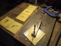
Drilled the plates out to 8mm which I presume would be the smallest I'd need, say for a 1/4" bit should that be of any use.
Not really sure what would be the best choice, if my half inch straight bit arrives for the router, it may be the only one I'll have
for a while...:unsure:

The pair of holes in one of the plates means one ring opening won't be any smaller than that.
SAM_9214.JPG
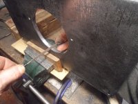
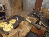
Roughly shaping one larger disc of the set to get the fit
SAM_9217.JPG
And rigged up the disc to finish on the sander.
Nice to find out the height of the benches happen to suit each other exactly for this task, though I hate moving that lump of a sander about... must ponder on that some.

SAM_9222.JPG
 
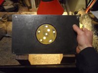
Got the first disc/insert ring fitted for the next job
SAM_9233.JPG
and cut four rings from some pipe
SAM_9243.JPG
SAM_9253.JPGThe vice came in handy for getting the fit rightSAM_9254.JPG

SAM_9257.JPG
and ground some chamfers to get them welded up
SAM_9264.JPG
 
Last edited:
Got the retaining lip thingy welded up, not without a fight I might add!. 😅
Might need a bit of a scrape in spots, must look for another marker for the job.
SAM_9268.JPG
Went well enough, though I ended up with it on the wrong side, as there's evidence of a little bracket on the top side, though not enough to upset anything atall.
'Twas drilling the corner holes from the wrong side which threw me off there.
Should be plain enough sailing for the rest.
Seems there will be no need for magnets or anything like that, though it looks like it might prove a challenge
to swap out when changing bits, considering that I'm hoping to weld an inner ring to keep things locked in,
just to be sure.

SAM_9271.JPG
 
Hopefully I can give ye an update later on things, as didn't get into the shed much since...
I'll add some pics to this post, as it will make better sense in a bit.
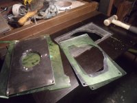
All done so far was to drill out five holes in each on the smaller plates for welding to the upper portion.

Scribed five points
SAM_9275.JPG

Might as well post some more on the subject of indexed drilling, especially since it didn't go as nicely as the last time,
and I can show where I went wrong.

To start off, I need to get some new ply specifically for the drill, and try again sometime.
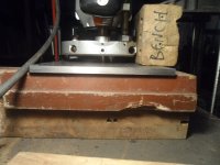
I think two layers is sufficient and about the size of the table, not in contact with the column being one thing needs addressing,
You can see it's too large of a board
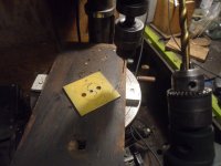
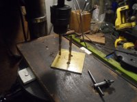
Clamping it down, drilling, rotating the work and drill again,
"get the table out of the way" to drill for the pin in the board, and back again to the same spot, which could be done a few ways...

Why ever they don't make pillar drill columns twice as thick to allow for a slot, is beyond me.

SAM_9279.JPG
I should've also pecked the second hole below
SAM_9282.JPG
And only drilling for the pin thereafter
was thinking the pin would aid rigidity here, hence where I went wrong.
Nice to have the opportunity to practice with something of no importance.
SAM_9286.JPG

Back on track again
Was originally going to ask a question sooner, but to say I've decided to "change tack" might be an apt phrase! :D
(sorry)... as I was planning to keep the upper "lamination" (for want of a better word)
on the rest of the "rings" unshaped, to aid holding for drilling in the vice.SAM_9291.JPG

I've since decided it would be better to shape and fit both "laminations" in situ on the insert plate,
hence some of my questions aren't immediate, but still curious as to know for when I'm finished with it.
Having looked for a good bit on youtube, I'm failing to find an answer.

Is there a need or benefit to having a zero clearance insert on a router table?
Granted my steel ones might be a recipe for a chipped cutter, so will be drilling suitable oversize to account for that.

A request of a mention on where to look regarding what one would call "unsupported work" would sure be interesting,
as from what I can make out...seemingly a lot of leeway in regards to that !🤨
I suppose tell tale ripple marks on the timber is where the issue will show up, rather than destruction,
yet still cannot find anything on the subject, and these are aplenty.

With that mentioned, a likely annoying recommendation of what size bores these three inserts should have would be
appreciated, for someone who doesn't even envision using the thing that much, being more a hand tooler.
It'll not make sense to some, but materials at hand prioritizing sequence of things what gets done in my shed,
so only wishing to be getting this project out of the way for now.

Cheers
Tom
 
Last edited:
Getting eager to see how the next stage will fair out, finished off the rough cutting
SAM_9296.JPG

This wee chainsaw file (twas in the chainsaw section) is a fair bit smaller than it looks here, and was great for a little scraping
of the bottom.
SAM_9298.JPG

Nice to have the belt sander proving its worth it's keep
SAM_9304.JPG

Wasn't expecting this to be great, but reckon a bit of filler would do the trick if need be.
Wouldn't be surprised if the fit changed somewhat once the discs are welded
SAM_9310.JPG

Hoping these will be tight still
SAM_9311.JPG

Just a few things left before finding out how this will go.
SAM_9320.JPG

All the best
Tom
 
That didn't turn out too bad at all, I was expecting the plates to move about.
Few tacks before getting everything off that black stuff.
SAM_9325.JPG

Lousy welds, but I was proceeding with caution.
I didn't rig up anything for holding the discs when angle grinding, and had a few slips,
so I tried resting these on a glove which made things easier.
SAM_9328.JPG

SAM_9332.JPG

Really should have scribed another circle when marking out those holes, as the weld marks show through.
Also to make note of the little burrs on the plate, this was from the fitting,
so a good idea to fit from the non show face.
SAM_9334.JPG

Only a few things left to do, and one being procrastanating over the bore sizes of the rings...
One will be bored out to a half inch for alignment, and then whatever beyond that to best suit a half inch cutter I've got.

Perhaps one will be left as is, at 8mm to suit a quarter inch bit.
and after a quick ask on the luthiers forum,
not just to see if I was unaware of a use for the router table and the associated cutter for the job...
but to try and find a sceanario of what could be called an "unsupported cut" which presumably might be most apt of a
place to go to in that regards.

Alas I didn't find a requirement for having a zero clearence insert, well not yet anyway.

One suggestion was to make provisions for an inch and a half roundover bit, so I suppose I'll be trying to find out what
size bore would be the most sensible choice for other useful bits around that size also,
seeing as there seems some leeway here, correct me if I'm wrong.

Cheers
Tom
 
Always marvel at the metal working/engineering side of things. Its not something I've done but that doesn't stop me admiring the work of others. This is an interesting build to watch and i have nothing to offer other than praise and thanks for posting.
 
Always marvel at the metal working/engineering side of things. Its not something I've done but that doesn't stop me admiring the work of others. This is an interesting build to watch and i have nothing to offer other than praise and thanks for posting.
Already forgetting the upgrade to the forum you've done Alasdair?
It sure makes things a doddle for posting, so it's us who should be thankful to yourself.

Still seeking some kind of answer as to what three sizes of ole's in these insert rings I should be considering,
and as of yet only drilled a half inch hole for alignment,
which will be drilled out for some wiggle room to suit a half inch cutter, exactly as to how much oversize I have yet to decide on.

It's not easy to find any sort of rule of thumb on this, not really knowing what might be more useful than I might think,
and I've been looking at some panel cutting bits from Trend for a rough idea....
aswell as some bits I might actually reasonably foresee, like the 1/4" and 3/8" core box bits for the wood hinge.

I should mention provisions were made when marking out the opening, to account for one of those Freud 3 1/2"panel cutters, which I guess might just be the largest thing one might be able to find.

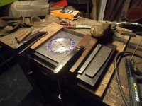
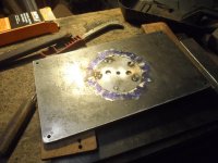
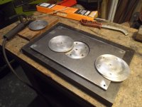
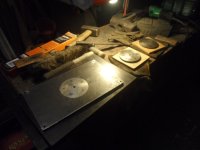
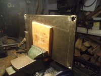
SAM_9339.JPG

Some of the last work is done finishing up the plate, had another go at marking out these mounting holes,
this time I used some gentle persuasion instead of doing a better job of chucking up threadbar in a drill for sharper points.
SAM_9344.JPG

Probably should've tidied up things before I started, but countersinking the holes gave me a better idea of things
SAM_9346.JPG

Everything ended up fairly good upon fitting, and the 1/2" bar stock only rubs slightly on the insert.
SAM_9351.JPG
Didn't take any more pics as not much to see.
Tidied up the plate and rounded the corners to suit the countersinks, which by chance happens to be the same radius as a
cutter I've got in this yoke.

Yet to rig up for the job, and not looking forward to working on this black stuff.
I've picked meself up a half price "shop vac" recently from the middle isle...
and really hoping this job won't stink out the thing forever more!SAM_9353.JPG

All the best
Tom
 
Well.... time came for the job of sinking that plate.
Let me start off by saying there's no decent router tutorial out there, well at least not what I've seen,
and as far as I'm aware, there's no website containing woodworking content called "real tube" :mad:
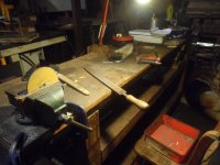
i.e without all the gizmo's you see on d'telly for sale.
and that ain't saying I haven't seen my fair share.

I probably made about 10 errors, at least...
Sorry I wasn't taking pics, way too messy and still got some junk in me eye.
Let me start off by mentioning finding a router bit the correct profile, which looking back, was my downfall.
It wasn't a fancy flush cutting bit mind you, just a bog standard one.
This is what I mean by lack of tute's on the subject, and I'll do my best to warn others of this approach.

The basic cutter required some cleats all round, with emphasis on the router being in contact on one specific point,
which should probably have been the narrowest point rather than using the widest like I've seen mentioned.
You really need a cylindrical baseplate for these if wanting to do this mallarkey.

The corners were an absolute nightmare and required a slip from what became apparent, just to get in tight to the corners.
I think this is where my cleat slipped a bit, during a bash transitioning directions.

Knowing what I know now, I wouldn't attempt such chance again, aligning the cutter tip by eye with the line.
well at least I'd be having a heck of a lot of go's if I needed to, as I overshot the line by a country mile in both orientations.
One of those errors I put down to misjudging things, whilst the other must have slipped.
I was expecting to sneak up on it.

I certainly need a better method of lining up the cutter tip with the line, not seen anyone mention many possible
solutions on this, like even a block to scuff off to act as an edge finder.
(if even just to make sure both sides are equal)

There's just too much to mention for there to make sense of, so I'll just say to someone in my shoes.
Wanting to try sinking a router plate without fancy bits?

Try finding a video on the subject, with only the kit what you've got.
Don't be surprised that you cannot find one dealing with internal corners and regular bits.

Really miffed I couldn't have learned all that from someone else,
That would have made an interesting watch, and saved me a lot of bother.
A clear example of how geared up for selling youtube has become, that no one does things the "hard way" anymore.

How about another one, depth stopping, likely requiring some paper for the job,
Another balls up regarding depth.
Pity I didn't have some ply or something to mock up for the job.
That and a baseplate might have been successful.

None of the things mentioned above are alluded to in all the videos I've seen.
along with some more little surprises what was down to being a numpty.
Guess I'll have to make up some paste or something, once the place is cleaned up.
Not pleased at all.
Grrrrrrrrr

Might not bother updating this **** show, as it's displeasing to say the least.
All the best
Tom
 
I am afraid that I can't take any credit for teh website update (different Alasdair). I have to sympathise with the setup of the inset plate these things always appear straight forward especially when you have done so much intricate work, then things don't go as planned. don't give up and i am sure there are plenty on here who can help all you need do is ask. As i was once told the only daft question is the one you dont ask.
 
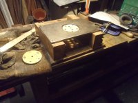
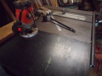
Routed and drilled out the wing, not without tribulations I might add,
If I were doing this job again, i.e with a suitable sized cutter for the corners, but without a fancy bearing to guide it,
I'd make sure the router could be trusted to be cylindrical, and either make it so, or make a plate for it.
Not plunging into the corners, and perhaps adding something which can be removed to sneak up on the line.

Somehow I think I had an oopsie with the drill
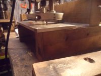
SAM_9374.JPG
 
Some shimming required also
SAM_9382.JPG

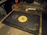
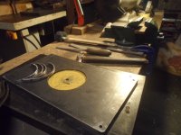
Done some testing and things went well, got thinking about how to keep those rings put,
Too much procrastination on how best to do it, as was thinking the other rings would need some jiggery,
but it turned out they only needed a straight chamfer with a chainsaw file.

This has simplified things nicely, not needing/wanting to pull out the kitchen sink as it were,
to bore out the other two holes to whichever size need be. :)
SAM_9383.JPG

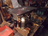
Some mock up shots of my new shop vac, not being tested yet, as I was pondering about making a sort of bell mouth for the small amount of debri it shoots out.
vlcsnap-2024-08-12-23h51m31s950.png

Quite pleasant really, compared to most any other time I've ever used a router!.

Calling this job done for now, not wanting to make any bells or whistles for it, until I sort out the other far more important side of the fence with some sorta extrusion.


vlcsnap-2024-08-12-23h52m41s159.png

All the best
Tom
 
Back
Top