• Hi all and welcome to TheWoodHaven2 brought into the 21st Century, kicking and screaming! We all have Alasdair to thank for the vast bulk of the heavy lifting to get us here, no more so than me because he's taken away a huge burden of responsibility from my shoulders and brought us to this new shiny home, with all your previous content (hopefully) still intact! Please peruse and feed back. There is still plenty to do, like changing the colour scheme, adding the banner graphic, tweaking the odd setting here and there so I have added a new thread in the 'Technical Issues, Bugs and Feature Requests' forum for you to add any issues you find, any missing settings or just anything you'd like to see added/removed from the feature set that Xenforo offers. We will get to everything over the coming weeks so please be patient, but add anything at all to the thread I mention above and we promise to get to them over the next few days/weeks/months. In the meantime, please enjoy!

Side Bender

Malc2098

Sequoia
Joined
Jul 3, 2016
Messages
8,322
Reaction score
1,367
Location
Tiverton
Name
Malcolm
I've had quite a lot of enjoyment out of making the Martin 000 12 String and finishing off my 1999 Dreadnought, that I thought I might make some more as well as a couple of ukulele.

This time however, I am not at evening classes being mentored as with the 1999, nor shall I buy a kit, like this year's model, which although could be good for a newcomer, is still quite an expensive way of going about it.

So I have researched material suppliers and found I can buy lesser visual quality timber, but still having a respectable sonic quality, from suppliers abroad, at such a price that in the case of guitar sides, I could buy some as practice pieces. I've found the British suppliers have excellent quality timbers but with the price to match.

Also, one other process that I need to undertake myself is the bending of the guitar and ukulele body sides. For my 1999 model, I had access to a heating iron at the evening classes and while rubbing back the lacquered body, I could feel the threepenny bit shape that I had managed to create. The 2000 model Martin came with the side already bent in the kit.

So for your delight, and mine, I have sourced the component parts to make a guitar side bender, and they are on the bench in the photo below.

IMG_4718.JPG

Technology has moved on and although bending irons are still available, the industry tends to prefer this method. On the bench you will see a silicone heating mat, shim steel, digital thermometer, a small heating mat, a veneer press screw and some shock cord and springs. Out of camera shot are a sheet of 18mm ply and 18mm mdf.

The industry bender model that is available for retail purchase is almost in 4 figures! :o

As I progress with this build, I hope to explain what does what as I go along.

Please watch this space.
 
That looks like a good thing to make, of course it's a step up from the blow lamp and a bit of steel tube.
Luckily I don't need one for the bass.[emoji41]
 
DaveL":2enbli4w said:
That looks like a good thing to make, of course it's a step up from the blow lamp and a bit of steel tube.
Luckily I don't need one for the bass.[emoji41]

How crude!! :D

Of course, if anyone what's their sides bent............ :D
 
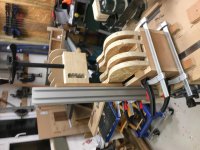
Testing the cantilever principle with some leftover 30x60 extrusion for the screw press.

IMG_4729.JPG

IMG_4730.JPG

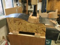
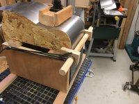
The principle appears to work. The cantilever arm can also be height adjusted on the extrusion to accommodate different size forms, e.g. concert ukulele and Dreadnought guitar.

The cantilever arm permits a small body/framework to support it and allow the forms to be placed on from the front and also allows the 36" long sandwich of shim steel, wood guitar side, silicone blanket and another shim steel to placed on and taken off from the front, rather than being fed through the two legs that previous designs required.
 
Andyp":1sm692kr said:
Not sure I understand but fascinating nonetheless.

I'll try and explain as I go along, Andy. The screw press will bend the guitar's waist.

I hope it will become more apparent as the machine builds.
 
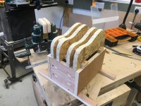
Putting together the prototype base for the bending machine with a ukulele form on top. This is a completely scratch built project with no drawings to go by.

CFEDB38F-4905-4DD8-A758-DF3F1A503101.jpeg

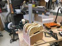
The image is beginning to show how the cantilever arm allows the screw to press a caul into the waist of the side to be bent, which is the first bend that the machine undertakes in the process. I'm trying to design the machine so it can take the small size of ukuleles as well as the standard sizes of guitars.

It's been interesting following the 'ordering direct from China' thread because I have been looking for a PID Temperature Controller to manage the heating of the silicone mat. The online market appears to be flooded with Chinese versions, all very similar.

I've ordered from a British supplier a controller made in Brazil, that although dearer, but not by much, than the Chinese variants, actually has more functions then them.
 
I will watch this with interest. It is a long time since I made an acoustic, and I did it with the "former" method which creates a mould for a given shape, both inside and outside. In my case I really liked the D45 and as I had one from 1972 (still do) I copied that exactly. When I started making guitars and up until I stopped really, Brazilian rosewood and Indian rosewood and very nice straight maple were readily available. I know its expensive now, but once you've tested your system, there is so much work in an acoustic guitar that it is worth buying good wood.

Your method looks clever if it can be used to develop several shapes and sizes of acoustic. Really keen to see how well it works. Excellent thread. You are getting me interested in guitars again. Glad you have moved away from kits.

Best regards, Adrian
 
AJB Temple":38eoy4p8 said:
I will watch this with interest. It is a long time since I made an acoustic, and I did it with the "former" method which creates a mould for a given shape, both inside and outside. In my case I really liked the D45 and as I had one from 1972 (still do) I copied that exactly. When I started making guitars and up until I stopped really, Brazilian rosewood and Indian rosewood and very nice straight maple were readily available. I know its expensive now, but once you've tested your system, there is so much work in an acoustic guitar that it is worth buying good wood.

Your method looks clever if it can be used to develop several shapes and sizes of acoustic. Really keen to see how well it works. Excellent thread. You are getting me interested in guitars again. Glad you have moved away from kits.

Best regards, Adrian

Thank you, Adrian. I shall be making moulds, too. This is just to bend the sides before they go in the moulds.

I order my timber from a supplier in Spain. UK suppliers have top quality woods. As an amateur, I don’t require the best quality, and indeed, I need to practice bending sides and could break a few while trying. So I order cheap, less than £10, sides of African mahogany to start me off. I have ukulele sides, too, which also quite cheap. I also have a small stock of local ash which I aim to cut and be the first practice pieces on the bending machine.
 
Thanks, Gents.

Technology has moved on and the bending iron has given way to the bending machine, and the temperature controllers have been improved, too, and if I’ve got it right, the one that I have ordered, once the mat reaches the set temperature value, as the temperature drops the controller pulses via a solid state relay to the mat to maintain that set value.
 
Once its done, ill send the mahogany sides to you then yer? Save me bending them.:) just flattern them out for posting back though, else it will cost a fortune.
 
Phil":3au0pvgv said:
Looks good Malc.

Reading with interest as this is way beyond my left-brain capabilities :o


Thanks, Phil. Mind you my brain need massaging on both sides quite frequently these days! :D
 
novocaine":2w6otrw7 said:
Once its done, ill send the mahogany sides to you then yer? Save me bending them.:) just flattern them out for posting back though, else it will cost a fortune.


I'll be happy to try and set up a side bending service for forum members once we can sort out an efficient shipping method.
 
Interesting. I am trying to guess what happens next without searching google as I am guessing you are not making metal bodied guitars :) . Obviously the aforementioned heating mats come into play soon as well as the actual wood that requires bending.
 
from what I've seen without googling, heating mat on shim stock to warm it up, wood on, another unbend bit of sheet ontop of that then the heating mat. slowly add pressure with the big thumbscrew. add pressure to pull ends in. leave with heat for a bit then remove and let cool.

not sure about the small heat mat but possibly to concentrate heat on the waist.

bit like steam bending but with more control.

until recently I always wondered why we didn't steam bend sides. sometimes I'm an idiot.
 
Some people are soooo impatient! :D


There quite a bit more to go in to building the machine, mainly electrics.

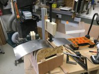
But, as you can see the shim steel will fit smoothly around the former. So, there will be a sandwich in this order; shim steel, heating blanket, wood side, shim steel. There will also be a temperature sensor fitted between the wood and the blanket. This will feed back temperature data to the controller.

The little mat will go on top of the wood and under the top shim at the waist with a temperature sensor and this will be the first part of the process, so that the wood on either side, that is the upper and lower bouts' bends, is not being prematurely heated while the waist is being bent.

While I say the wood is being heated, the wood in fact will be sprayed with water, not much, then wrapped in baking parchment and then wrapped in kitchen foil, and it is the steam generated by the heat from the mat that encourages the wood fibres to relax and stretch that allow it to be bent into the form shape.

That's the theory, anyway, but I have no doubt I won't get it right first time, so I will practice on some of my own stock rather than the luthier stock that I have bought.
 
meh. close enough. :)

the amount of control you will have the variables I don't think you'll have to much bother get a perfect bend with only a few initial losses if any. iIt's not as much of a black art as tube bending, which as I've learned from trying to bend wooden purfling and binding is no small feat to getting it right.
 
An offcut of hand rail from the balustrade outside on the deck makes an ideal caul for the waist. :)

IMG_4832.JPG
 
Malcolm I am curious to know how a) the heating pad will cope under pressure. and b) why you are not steaming the wood before putting it into your machine for bending.
 
MY63":26xxtapu said:
Malcolm I am curious to know how a) the heating pad will cope under pressure. and b) why you are not steaming the wood before putting it into your machine for bending.


Michael, as I understand it, there is limited pressure on the heating mat. I think the silicon is similar to the stuff used in cooking, although I am not sure what the element inside consists of.

The pressing of the caul is only done very gently as the the wood relaxes, and it does not force the wood, as I am sure that will cause a break. The steel is used to maintain the sandwich to the shape of the form, rather than pressing it. It's shim steel of .010" thickness.

I am yet to make the cauls that bend the upper and lower bouts and they will be moved outwards from the waist, one at a time as the wood relaxes until they can get down to the end of the wood. Again this will be done carefully with out undue pressure on the wood.

I will spray the wood both sides before I wrap it in baking parchment and then kitchen foil. The parchment helps to contain the sprayed water within the wood rather than escaping to atmosphere and the foil prevents the steel from staining the wood.

I believe the heating mats are so efficient that there is no need to heat the water or steam the wood before hand. The temperature controller, with my programming, will allow the mat to heat up, maintain the temperature for as long as I have set it while I am gently pressing it into shape, and then I will lower the temperature to allow the wood to take up the shape before allowing it to cool to room/workshop temperature.
 
..and the lower bout.

09E28C8E-8EAD-40A6-B310-582DFD192E7C.jpeg

7601E472-4F6F-4BE4-B088-4C0527233E67.jpeg

020CAAC4-32F0-45B9-A2FA-EC447B8E1A57.jpeg

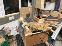
I think bungee cord has turned out better than steel springs because they can pass round the cantilever post relatively easily.

That was a dry run without the thickness of the wood, silicone mat and a second steel sheet and without the heat generated.

Now I've got to duplicate this for a standard sized guitar form.
 
Just proved the theory that it can cater for standard sized guitars, and possibly an acoustic bass, down to a concert ukulele.

9FBFFA60-B788-4506-85BF-5E321446FC16.jpeg


All I've got to do now is fit the electrickery! :shock:

67F95E68-7AD4-44A6-B9BA-EBCDD30AF9BE.jpeg
 
Time to start fitting stuff.

6F035226-E1CA-4D70-832F-4C7FABB3172B_1_201_a.jpeg

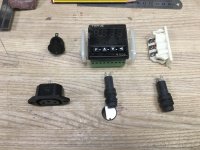
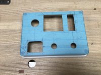
So, firstly, I have to cut out the panel silhouettes from a plastic enclosure of an illuminated SPST switch, the Novus PID digital temperature controller, a 3 pin socket for the PT100 thermocouple cable, two panel mounted fuses, one for the main circuit and one for the heating circuit, and a C13 female power outlet to plug the lead to the silicone heating blanket.

6F8E17E4-A02B-451E-AF39-5569B236F7F0_1_201_a.jpeg


I had a cheap copy of a dremel but it didn't have any circular saw blades, so I used forstener bits and files to cut out the silhouettes having first covered the enclosure lid with blue tape and drawn the apertures on there.


Thankfully they all fitted.

B9AFB64B-5A56-4029-BADF-362CD198FA41_1_201_a.jpeg

The Novus supplier recommended a circular isolation switch, but they were so big, I couldn't find anywhere on the bender box to fit it, so I got the smallest lever isolation swish I could find.

Also have to find somewhere to fit the Solid State Relay and its heatsink within the box, but that's for tomorrow.
 

Attachments

  • 30273D0F-3B42-4288-8764-0FB0959B7344.jpeg
    30273D0F-3B42-4288-8764-0FB0959B7344.jpeg
    324.1 KB · Views: 5,761
The heatsink is not going to be any good inside the box.
Normally cut a hole in the side of the box so the SSR is on the inside and the heatsink on the outside. The heatink and SSR need to be in intimate contact and the heat sink must be grounded.

Bob
 
9fingers":2o5tgkg5 said:
The heatsink is not going to be any good inside the box.
Normally cut a hole in the side of the box so the SSR is on the inside and the heatsink on the outside. The heatink and SSR need to be in intimate contact and the heat sink must be grounded.

Bob


Thanks for that, Bob.

I've got the thermal grease ready for the intimate contact. The box is not six sided. It is open top and bottom, the bottom is raised from bench surface by feet used to clamp to the bench.

I would have to provide an aperture to be able to view the LED on the SSR anyway, and was hoping that a bottom to top airflow through the box would dissipate the heat from the sink. But will obviously consider and inside out arrangement, too.

I am awaiting hearing back from the family sparks and the Novus supplier on the wiring diagram which included grounding the heat sink.
 
Tis the work of a madman. Admit it, you went with the lever so you can throw it and laugh manically.
 
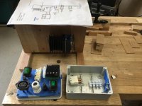
All the components have now arrived. Discussions with the Controller supplier have resulted with him supplying me with DPST switches for the isolators and he's agreed the wiring diagram. The SSR and its heat sink are now attached to the outside of the machine box.

D6D3CDA7-B0D7-4483-8A30-20C42C2C60A7.jpeg

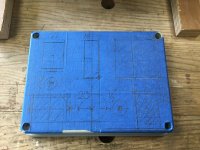
So, time to start making the apertures for the components of the control panel.

Out came the blue tape again.

E15B3075-73E8-4046-AFBF-6E814FD9EEA3.jpeg

Over to the drill press.

A0DD4EB9-F72A-4C7B-958A-8F99E15E7DA4_1_201_a.jpeg

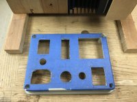
Out came the files.

4547649E-4CD7-4394-9B8A-D617F9C6092A_1_201_a.jpeg

Off came the tape.

838BF8E8-2BC5-4019-83DB-B3CA94FFB26A_1_201_a.jpeg

In went the components.

4EDDC0CC-9C4D-41DC-85C6-B2FC9DD68C83_1_201_a.jpeg

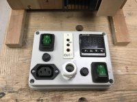
I've arranged the power in and thermocouple in in the centre. The Digital PID Temperature Controller, its fuse and isolator switch are on the right. On the left are the power out (to the heating mat) and its fuse and isolator switch.

Time to brush up on my soldering.

A3ED3CCC-9837-4828-9B58-2D5CC4D743A2_1_201_a.jpeg
 
Thanks, Gents.

I'm afraid I'll never win any neatness competitions for wiring!

95D2AD21-A44E-4DBE-9055-E0EA5055965F.jpeg

I decided the enclosure space was too small for my wiring and I could possibly find another means of bolting the front panel to the side of the box, leaving the backside of it exposed and therefore easier access for the wires to and from the SSR on the outside.

That's tomorrow's problem to solve.
 
Back
Top