• Hi all and welcome to TheWoodHaven2 brought into the 21st Century, kicking and screaming! We all have Alasdair to thank for the vast bulk of the heavy lifting to get us here, no more so than me because he's taken away a huge burden of responsibility from my shoulders and brought us to this new shiny home, with all your previous content (hopefully) still intact! Please peruse and feed back. There is still plenty to do, like changing the colour scheme, adding the banner graphic, tweaking the odd setting here and there so I have added a new thread in the 'Technical Issues, Bugs and Feature Requests' forum for you to add any issues you find, any missing settings or just anything you'd like to see added/removed from the feature set that Xenforo offers. We will get to everything over the coming weeks so please be patient, but add anything at all to the thread I mention above and we promise to get to them over the next few days/weeks/months. In the meantime, please enjoy!

"Universal box joint jig"

Malc2098":3sl3yicm said:
It is said that the X type, the Mondeo and the Mazda 6 share 60% of their parts!

Good luck with the jig. Still following!

Indeed, quite a few car groups use similar/same floor pans on which most of the running gear bolts onto. a great saving for them.
Lots of spares for my car (54 plate Cmax) are common to volvo, peugeot and citroen as well as vehicles through the Ford range and interestingly sold at different prices according the vehicle type quoted.
I quite often stock up on citroen filters when in France and carry a inter model crib sheet in my travel docs.
Tight? me nah but I hate being ripped off!

Bob
 
I'm still in the room with you and Stu, Bob… :shock: :oops:

Must admit it's not clear to me how the pin adjustment will work, even after reading your description and looking at the diagram, so I'm not commenting but waiting to see how it progresses and I'm sure it will become clear to me then.

Cheers
Mark
 
I'm following this with interest but need to see something visual working to get my head around what you are making. It will be very nice to see the item under construction and even more so demonstrated. Quite an unusual and interesting project.

Mark :text-bravo:
 
OK chaps now I have some jobs out of the way, been out to lunch with mates etc it time for the next installment.

Firstly I would suggest you look at this video https://m.youtube.com/watch?v=NutwD7B6tmE mainly about the fit and glue clearances etc.

This is how I plan that the my jig would be used.

Take the width of the boards you want to join and decide the number of pins and sockets you want to use this can be for a symmetrical joint ( each end different) or asymetrical ( both ends the same).
work out the socket width and set the dado to cut that. If you are router based or simply stacking saw blades.
Then you might want to adjust the stock size around your achievable cut width.
Set the blade height to the board thickness or very slightly more - certainly no less. Lock the height adjustment.
Take a pre-prepared backer board of constant thickness and hold on the jig fence and make a cut in a single pass.
Remove the backer set aside to be used as the reference for the socket width.
Set the left hand guide to be slightly more than the socket width.
Take a piece of scrap just less that twice the width of the socket. Make sure the end is cut off square.
Push that against the left hand side of the left hand guide and pass though the saw.
Try the resulting pin in the socket cut in the backer board.
Adjust the left hand guide as required to a fit in the socket that is smooth and has an allowance for glue.
Tighten up the left hand guide, fit the backer over both guide pins and move the right hand guide leftwards as far as it will go. Check the backer slides on and off the pair of pins nicely and is not flexing the pins.
Tighten the right hand guide.
Now you are ready to run a test set of box joint cuts in the conventional way as per most of the video on this type of pin jig and see how they fit and how the pins and sockets are distributed across your chosen stock width.

So far this is all theoretical but I think it should work and hopefully I will not need to change the above.

For those of you intending to make a jig for your router tables then omit the right hand orange guide strip and position the left hand one to suit the slot in your router table.
If like me you don't have any guide slots, push the router fence as far away from the cutter as possible and lock it. Just make the jig fence part of the design and arrange to run that against the surface of the table fence.

That's it for now folks.

Have you noticed? Not a measurement in sight for setting up. Everything is driven by the fit of the pin in the socket.


Bob
 
OK lets get into some detail and some sums! :shock:

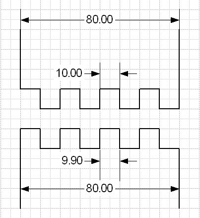
firstly the assymetric joint like this


Lets say the stock is 80mm wide and each half will have 4 pins and 4 sockets.

80/(4+4) = 10mm so we set the dado to 10mm and each piece gets 4 x 10mm sockets. We also have 7 joints between each piece and say we use 0.05mm clearance (2 thou in old money) so that is 0.35mm of clearances.
therefore the pin size = (80 minus 4 sockets minus 0.35) divided by 4.
Pins come out at 9.9125mm (working to a stupid number of significant digits for now)
top and bottom pieces are the same simply flipped left right
Nice and easy.

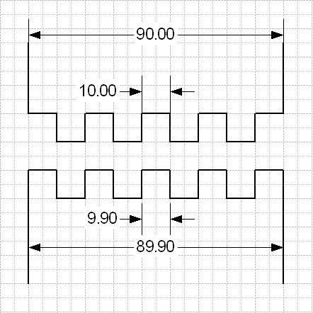
Now if we look at the symmetical joint - which I prefer visually, it looks like this.


The top piece has 5 x 10mm sockets and 4 pins. To keep the numbers easy the board is 90mm wide. Sticking with our 0.05mm clearance this time on 8 joints. We have the pin width of 9.9mm.

Now we plug the numbers into the bottom board with 4 sockets at 10mm and five pins at 9.9 plus 8 x clearances of 0.05 we get a board width of 89.9mm. oops!

OK it is only a gnats tadger out but enough to offend an engineer but a couple of swipes with one of those plane things you guys like to use and no one will notice.

So for perfection use the asymetric layout and ignore what it looks like because it will be RIGHT! :lol:

Bob
 
I'm also sitting quietly in the corner :)

Re your EGR...do you not have one of those gizmo's that plugs into the diagnostic socket and an app on your phone? I've reset many a glitch...saved me £££££
 
RogerS":3pvr22hl said:
I'm also sitting quietly in the corner :)

Re your EGR...do you not have one of those gizmo's that plugs into the diagnostic socket and an app on your phone? I've reset many a glitch...saved me £££££

Of course I do Roger. I kept resetting the DTCs and they persisted in returning which is what drove me to investigate. I was still suspicious as on Saturday it had sailed through its Mot emissions test.

As far as the jig is concerned you have two more posts stuffed full of detail to read now!

Bob
 
Watching from afar too here - not been posting for a few weeks due to work commitments and jobs at home that are urgent (put up a 30m2 carport, gates and repaired a sash window the window cleaner broke in the last couple of weeks) but am still interested in this jig!

Steve

PS - don't know anything about EGRs!
 
Watching with interest Bob but I have a Woodrat which does the joints it's own way.
My saw (Deft T30 - similar to a Laguna) will take a dado but I don't possess one.

Rod
 
9fingers":29q67e9e said:
OK chaps now I have some jobs out of the way, been out to lunch with mates etc it time for the next installment.

Firstly I would suggest you look at this video https://m.youtube.com/watch?v=NutwD7B6tmE mainly about the fit and glue clearances etc.

This is how I plan that the my jig would be used.

Take the width of the boards you want to join and decide the number of pins and sockets you want to use this can be for a symmetrical joint ( each end different) or asymetrical ( both ends the same).
work out the socket width and set the dado to cut that. If you are router based or simply stacking saw blades.
Then you might want to adjust the stock size around your achievable cut width.
Set the blade height to the board thickness or very slightly more - certainly no less. Lock the height adjustment.
Take a pre-prepared backer board of constant thickness and hold on the jig fence and make a cut in a single pass.
Remove the backer set aside to be used as the reference for the socket width.
Set the left hand guide to be slightly more than the socket width.
Take a piece of scrap just less that twice the width of the socket. Make sure the end is cut off square.
Push that against the left hand side of the left hand guide and pass though the saw.
Try the resulting pin in the socket cut in the backer board.
Adjust the left hand guide as required to a fit in the socket that is smooth and has an allowance for glue.
Tighten up the left hand guide, fit the backer over both guide pins and move the right hand guide leftwards as far as it will go. Check the backer slides on and off the pair of pins nicely and is not flexing the pins.
Tighten the right hand guide.
Now you are ready to run a test set of box joint cuts in the conventional way as per most of the video on this type of pin jig and see how they fit and how the pins and sockets are distributed across your chosen stock width.

So far this is all theoretical but I think it should work and hopefully I will not need to change the above.

For those of you intending to make a jig for your router tables then omit the right hand orange guide strip and position the left hand one to suit the slot in your router table.
If like me you don't have any guide slots, push the router fence as far away from the cutter as possible and lock it. Just make the jig fence part of the design and arrange to run that against the surface of the table fence.

That's it for now folks.

Have you noticed? Not a measurement in sight for setting up. Everything is driven by the fit of the pin in the socket.


Bob
Still with you Bob!

I think there's a more elegant solution to set the width of the pin rather than the set/adjust/set/adjust/try routine.
Take a piece of scrap (setting board), lets say 3 times the width if the cutter/dado, with parallel sides and run it through the jig with the cut out somewhere near the center which will give you a piece with two legs at one end. If you cut one of the 'legs' off and move it across to join the other leg, the difference between the width of the original board and the width of the two legs is the size of the pin that you want less the glueing tolerance or about a piece of paper. Set the left hand side of the left pin on the right hand side of the blade, move it right by the width of the setting board position, then move it left by the width of the two legs plus a piece of paper and it should be in the perfect place. I hope that makes sense, it's late and I'm tired!
9fingers":29q67e9e said:
OK chaps now I have some jobs out of the way, been out to lunch with mates etc it time for the next installment.

Firstly I would suggest you look at this video https://m.youtube.com/watch?v=NutwD7B6tmE mainly about the fit and glue clearances etc.

This is how I plan that the my jig would be used.

Take the width of the boards you want to join and decide the number of pins and sockets you want to use this can be for a symmetrical joint ( each end different) or asymetrical ( both ends the same).
work out the socket width and set the dado to cut that. If you are router based or simply stacking saw blades.
Then you might want to adjust the stock size around your achievable cut width.
Set the blade height to the board thickness or very slightly more - certainly no less. Lock the height adjustment.
Take a pre-prepared backer board of constant thickness and hold on the jig fence and make a cut in a single pass.
Remove the backer set aside to be used as the reference for the socket width.
Set the left hand guide to be slightly more than the socket width.
Take a piece of scrap just less that twice the width of the socket. Make sure the end is cut off square.
Push that against the left hand side of the left hand guide and pass though the saw.
Try the resulting pin in the socket cut in the backer board.
Adjust the left hand guide as required to a fit in the socket that is smooth and has an allowance for glue.
Tighten up the left hand guide, fit the backer over both guide pins and move the right hand guide leftwards as far as it will go. Check the backer slides on and off the pair of pins nicely and is not flexing the pins.
Tighten the right hand guide.
Now you are ready to run a test set of box joint cuts in the conventional way as per most of the video on this type of pin jig and see how they fit and how the pins and sockets are distributed across your chosen stock width.

So far this is all theoretical but I think it should work and hopefully I will not need to change the above.

For those of you intending to make a jig for your router tables then omit the right hand orange guide strip and position the left hand one to suit the slot in your router table.
If like me you don't have any guide slots, push the router fence as far away from the cutter as possible and lock it. Just make the jig fence part of the design and arrange to run that against the surface of the table fence.

That's it for now folks.

Have you noticed? Not a measurement in sight for setting up. Everything is driven by the fit of the pin in the socket.


Bob


Sent from my GT-N8010 using Tapatalk
 
Yup I get that Stu, I agree it will work and that it is elegant/novel but still to be convinced if it easier.

Might work better if the small piece of leg is superglued back onto the other leg to make a single item which is easier to handle.

Once I've made the jig, I'll try both methods out.

Bob
 
I have a dado stack and will be looking at this, once I see how it comes together, keep up the good work Bob.
 
Here's a link to a video of someone setting up a 'kerfmaker' (cool little tool) showing the principal in action for those unable to follow my rambling post!

https://youtu.be/eFpNxtiSaYY

Funny you should mention super glue as this guy glues the off cut back on.

Sent from my GT-N8010 using Tapatalk
 
stu":14jz8t7k said:
Here's a link to a video of someone setting up a 'kerfmaker' (cool little tool) showing the principal in action for those unable to follow my rambling post!

https://youtu.be/eFpNxtiSaYY

Funny you should mention super glue as this guy glues the off cut back on.

Sent from my GT-N8010 using Tapatalk

That is a great little gadget Stu. On my round-2-it list for sure.

Bob
 
Experiments with rivet nuts.

I've known of these wonderful thing for ages but never used them for real until just now.

They consist of a flanged bush with a a thread cut in but only in the lower half opposite the flange.
Hopefully you can see enough in these two photos.


These are M6 ones and the body is 9mm diameter and the flange is 12.5mm. The overall length is 15mm as supplied.

I want the top surface to be flush when fitted to I needed a 9mm though hole with a 12.5mm counterbore 1.5mm deep

like this ( ignore the other holes this is a piece of scrap aluminium of the right thickness)


The bush is then inserted a bolt inserted to the full depth of the thread (important!!) and then with a thick washer and nut on the top face ( sorry no pic) the nut is tightened until it will go no more. The result is that the un-threaded portion has collapsed to fill the hole and form a neat swage on the back of the panel to rivet the bush in firmly. Takes less time to do than type this.

Final result looks like this from the back


and from the front


As a result of the compression. the bushes have shrunk from 15mm to 12mm just right for the design. Lucky or what!

I'll be using these on the adjustable parts of my jig.

Oh yes and I've bought some spares for you lot when you make your jigs :D

Nearly dinner time - snake and pigmy pie yummy!

Bob
 
What size rivnuts are you using? edit. just seen M6 - I have those somewhere. Mine have a smaller top flange so don't need countersinking for most applications.

I've probably got a few hundred of each size in stock. we used to use them by the 5000 box bought direct from Avdel. I have a hand setting tool for M4 ones as well. the tool also corrugates the flange slightly to resist spinning. Spinning in the hole is their main failing if not set correctly or cross threaded. Once they spin they need drilling out.

The correct way to set them is insert the thread of the insert tool then the tool pulls the bolt like a pop rivet gun would. Winding them set with the bolt soon damages the threads - not that it matters for a few nuts.
 
Getting drawn right into this post Bob, finding your description with pics very interesting please keep it up. It's a learning curve.

Mark
 
Robert":39tg1gdc said:
What size rivnuts are you using? edit. just seen M6 - I have those somewhere. Mine have a smaller top flange so don't need countersinking for most applications.

I've probably got a few hundred of each size in stock. we used to use them by the 5000 box bought direct from Avdel. I have a hand setting tool for M4 ones as well. the tool also corrugates the flange slightly to resist spinning. Spinning in the hole is their main failing if not set correctly or cross threaded. Once they spin they need drilling out.

The correct way to set them is insert the thread of the insert tool then the tool pulls the bolt like a pop rivet gun would. Winding them set with the bolt soon damages the threads - not that it matters for a few nuts.


I glossed over my fitting method. A nut is fitted to a long bolt, then a flat washer, then a thick steel bar. the bush it threaded on up to the back of the bar. the bush is fitted into the counterbored hole and the nut is turned to compress the bush until it is fully home. In this way the thread in the bush is not damaged in any way just the way the pop rivet type tool does it.
I bought a small bag of M6 alloy rivnuts on ebay for this job.
Bob
 
meccarroll":11x7aqn5 said:
Getting drawn right into this post Bob, finding your description with pics very interesting please keep it up. It's a learning curve.

Mark

Glad you are finding it interesting Mark. I've got some more drawing to check and then work from for the guides. They will come from standard 1" x 3" x1/8" aluminium alloy.
Believe it or not most extruded aluminium products are still imperial and the extrusion dies used don't wear out and are still in use years later....

Bob
 
Here we go with the next step. Making the guides.

This is what I'm going to make.


Edit: Oops first drawing error. The stock is 76.2mm long (top of the upper Drawing but by the time the finger has been reduce to 2mm thick, this dimension becomes 75mm :oops:

Firstly cut a couple of pieces of angle 50mm long from 3" x 1" x 1/8" aluminium angle and rough out the guide fingers on the bandsaw.


I did not take any photos of the machining steps but basically it involves cleaning up the sawn faces and then machining to drawing. The tricky parts are that extruded angle is very rarely spot on 90 degrees and so I used precision straightening techniques -belting it with a soft faced hammer :lol: to dress it to 90 degrees.
Also machining the fingers down to just less than 2mm thick needs to be done very carefully indeed, creeping up on the final size a little at a time. This ended up changing the stress in the angle and more adjustment to get back to 90 degrees.
I particularly want to try making 4mm pin box joints as I have a 4mm FTG blade but unless you really want to go this fine I'd suggest you limit your jigs to 1/4" pins and that means you can use the angle as supplied without all the f*rting about that had to do.

Having got everything machined, it was time to fit the rivnuts. Yesterday I did not show my method fully.

1. Take a piced of thick steel mine was 8mm and drill a 6mm hole near the end. take a long ish m6 bolt ( I used 50mm but it could have been 40mm) and thread on a nut and a washer. Pass through the 6mm hole in the steel bar and use the rivnut with the flange against the steel just tightened finger tight. make sure the end of the bolt protrudes slightly from the end of the rivnut like this.


Offer up the rivnut end to the job and secure with a couple of clamps leaving room for a spanner to fit onto the nut. This ensure that the rivnut will be fitted square to the surface and lets you concentrate on the spanner and the degree of compression.


and


Tighten the nut whilst watching the the compression taking place and stop when the nut be comes harder to turn. This should be when there is a nice neat bulge all round the rivnut stem.


Loosen the nut, withdraw the bolt and the job is done.

The end result, a pair of handed box joint guides viewed from each side.


Time for tea now - home made Fish & Chips mmm!

Bob
 
9fingers":n24oeoq3 said:
Time for tea now - home made Fish & Chips mmm!
Bob

I was enjoying this up until you wrote that. :D Now I am hungry. Please don't tell me you will wash it down with a nice bottled real ale.
 
Andyp":2a9kkbkc said:
9fingers":2a9kkbkc said:
Time for tea now - home made Fish & Chips mmm!
Bob

I was enjoying this up until you wrote that. :D Now I am hungry. Please don't tell me you will wash it down with a nice bottled real ale.


No you are quite safe. I almost never drink beer at home only the rare pint in a pub once every couple of weeks.
Traditionally F&C would be eaten with a mug of tea and bread and butter to make chip butties of course but we don't do that either. The only drink tonight will be from the perky copulator loaded with French coffee at about 8pm.

Bob
 
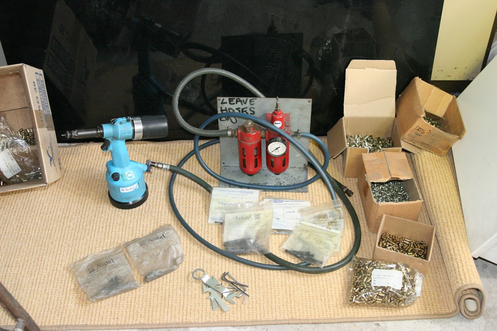
No relevance at all to what you are doing but I found a picture of the tool we sold when we closed the business..

Avdel.jpg


Went for £725 in 2006 as I recall. Sets them precisely with a cycle time of about 5 seconds. Auto spin on and off and setting pull of course.

Your way works just as well of course. If you can hit straight they will set with a hammer blow too as I've done it at home. We never used alloy rivnuts or flange headed types only steel or stainless flush types.

Not sure I completely follow how your jig will work as I've never thought about box joints before. Watching with interest but if I did have a go it would be router table based I think.
 
Robert":1w58rxip said:
Not sure I completely follow how your jig will work as I've never thought about box joints before. Watching with interest but if I did have a go it would be router table based I think.

Robert, could I suggest that you watch the youtube video that I linked to recently as that should give you the basics.

If you then read my description of the setting method, I hope it should be clear. If not please do say as it means I have not described it properly.
I don't have the equipment to do a video so I will not be doing a blow by blow account of its use as once set it is the same as the plethora of box joint jigs out there.

Bob
 
I had watched it previously but hadn't made the connection with your jig and its brackets :oops:
 
Yes.

Do you think your brackets will be strong enough? just thinking ali bends easy if you knock it...
 
Robert":1nr0lspi said:
Yes.

Do you think your brackets will be strong enough? just thinking ali bends easy if you knock it...

It is a concern. I would have used steel but for the interest here in making jigs. Most woodies are pretty metal phobic but at least aluminium can be worked using some versions of woodwork tools.

The blade guard should offer some protection and I don't think it will bend in use only in "abuse"

Bob
 
A bit more progress today in between domestic jobs.

The vertical fence after the recess for the guides was been cut out. I've used phenolic resin coated birch ply which I like to use for most jigs and fixtures. I is by no means essential comparte to other quality plywood but I happen to have a near lifetimes supply of the stuff. Many 8' long strips 6" wide left over from a cancelled job years back.

Whilst everything was set up in the mill I engraved a line to represent the blade reference line from the original drawing. Might be useful and a doddle to do whilst i was at it.


and from the other side (facing the operator)


Note that the guides have had short M6 studs fitted and loctitied into the rivnuts. This is important as the rivnuts are aluminium and will wear rapidly with regular movement. fitting a steel stud into them permanently will mean all the loosening and tightening effort will be done with a steel nut on a steel stud and last much longer.

The next views are of the fence with the guides fitted from each side.


Nice large washers to spread the clamping load on the back.

Thats possibly all until next week as I'm otherwise engaged tomorrow.
To follow the trend - Homemade lasagne for dinner tonight washed down with some red wine
Bob
 
The next report:

If you are the nervous type look away now.


Here is the dado head set up to just cut through the phenolic resin to allow the glue to take.

Here we have all the parts to be glued (apart form the runners) prepared.


The two fence components, the two triangular braces to help maintain the fence parts at 90 degrees and the parts for the tunnel blade guard.

I planed up an ash offcut to be a smooth sliding fit in the table saw slots and then ripped it into strips. It made five and I only needed two but the rest are stashed away for any other jigs that might need them.

Here is is all glued up and in the clamps.
Underside view


View from the tunnel guard end. This will be cut through when the jig first gets used.


Might get to try it out tomorrow after going for my flu jab.

Bob
 
Nearly there. I have a couple on metres of dentil moulding i need running out so i might pop round to give it a test run! [WINKING FACE]

Sent from my SM-G935F using Tapatalk
 
stu":fwtv6njx said:
Nearly there. I have a couple on metres of dentil moulding i need running out so i might pop round to give it a test run! [WINKING FACE]

Sent from my SM-G935F using Tapatalk

Due to the location of my saw, I can possibly on do just over a metre before I'd hit the wall :D

Curious that a tooth like moulding is known as "dentil" and yet things pertaining to teeth are "dental"??
One of the English language thread maybe.

Bob
 
I had to double check the spelling in case I'd made an error!

Looks like I'll have to do my moulding then.

Sent from my SM-G935F using Tapatalk
 
Acid Test time!

Well here is the jig set up (using the method I described way up the thread) for a 10mm wide socket.


I'd previously planed up some pine to 14mm thick and 40 wide and cut my first joint and it fits perfick!!

I would say that two pins and two sockets is not exactly an onerous test as the errors build up with the number of pins & sockets. From and engineering point of view all the cutts should be referred to the same datum but these jigs just don't work like that and the position of one socket depends on its neighbour.

I next cut a couple of test joints using my 4mm blade and boy were they tight and over 40mm (5 pins & 5 sockets is much more of a testing situation.

However adjusting by the thickness of a piece of paper made all the difference and number 3 attempt at 4mm was spot on - I'm a pleased as a dog with two -----successful box joints!


I would say if you are going for multi fingered joints then allow quite a bit of clearance in the set up say 0.2 0.3 mm and set the righthand finger to be a tightish fit. Any slack here can get multiplied up by the number of sockets. As with any joint preparing some extra stock of the same dimensions for test cuts takes little extra time and can even be of different (scrap) wood to the project pieces. Also dont forget the test strip which needs to be more than one socket with and no wider than two socket widths.

I did try Stu's alternative method of the kerf finder but it depends on setting against a tooth tip which could be a source of error if there is any blade wobble. My original method relies on the actual dimnsion cut by the saw and I prefer it.

A minor refinement to the design could be made regarding the guarding.

If like me you conveniently leave the adjusting spanner on the jig like this


then there will come a time when it slips into the slot left by the blade behind the fence with disasterous results.

This small area needs a cunning guard to sort the problem and yet not get in the way of the adjustment nuts.


All in all very pleased.
Before anyone asks there will be no video as I've not got the gear, inclination or editing software etc.

If you are going to make one and i hope you will then all the principles are laid out in this thread and a detailed written description of how to use it. The dimensions are going to depend on your saw or router table.

Good luck and happy box joint cutting.

Bob
 
Well done Bob. I use magnets on a few tools to hold allen keys, check keys and spanners in place.

Now what is the project that requires these box joints?
 
9fingers":3io4av4x said:
If you are going to make one and i hope you will <SNIP>

Bob

Or could you make them and offer at a reasonable cost to offset your materials and time? :eusa-think: :eusa-shifty:

Either way - nicely done Sir, nicely done!

Steve
 
Andyp":2az3ga17 said:
Well done Bob. I use magnets on a few tools to hold allen keys, check keys and spanners in place.

Now what is the project that requires these box joints?

That is a great idea Andy. I might follow that up although magnetised tools can be a real PITA in the engineering workshop.....

The first application will be to make some drawer boxes for the final stage of my barrister bookcase project which I really must get back to working on.

Bob
 
StevieB":3ivixfck said:
9fingers":3ivixfck said:
If you are going to make one and i hope you will <SNIP>

Bob

Or could you make them and offer at a reasonable cost to offset your materials and time? :eusa-think: :eusa-shifty:

Either way - nicely done Sir, nicely done!

Steve

Thanks Steve.

To be honest as I'm retired I'm relatively time rich and all the materials came from stock with the exception of the Rivnuts for which I purchased a small stock from Fleabay for a few quid.
If anyone wants a couple for little more than the postage in order to make this jig then just PM me.

Bob
 
Back
Top