• Hi all and welcome to TheWoodHaven2 brought into the 21st Century, kicking and screaming! We all have Alasdair to thank for the vast bulk of the heavy lifting to get us here, no more so than me because he's taken away a huge burden of responsibility from my shoulders and brought us to this new shiny home, with all your previous content (hopefully) still intact! Please peruse and feed back. There is still plenty to do, like changing the colour scheme, adding the banner graphic, tweaking the odd setting here and there so I have added a new thread in the 'Technical Issues, Bugs and Feature Requests' forum for you to add any issues you find, any missing settings or just anything you'd like to see added/removed from the feature set that Xenforo offers. We will get to everything over the coming weeks so please be patient, but add anything at all to the thread I mention above and we promise to get to them over the next few days/weeks/months. In the meantime, please enjoy!

Dr Al's Latest Folly

Dr.Al

Old Oak
Joined
Dec 31, 2020
Messages
3,516
Reaction score
2,157
Location
Dursley, Gloucestershire
Name
Al
After spending all of last year on my rather epic tool chest / workbench project, I've been flitting between various fairly simpler projects. I've now decided to get started on another relatively complicated project that should challenge me a bit. It probably won't surprise you to hear that this will probably be done in an overcomplicated way, but as usual: as long as I enjoy the process, I'll be happy.

The challenge I've set myself is to make some new chisel handles out of English Walnut. The choice of wood is based on the fact I've got a lump of English walnut that's quite short along the grain but quite wide and thick, so I think I can get lots of chisel handles out of it, but there's not much else I can think of that I could do with it.

This is roughly what I want the chisel handles to look like (they're 30 mm thick at the thickest point):

chiselhandlemodel_800.jpg


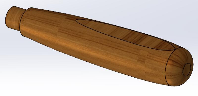
I've 3D-printed some test pieces to get an idea of how well they fit in the hand and they feel quite nice to me, so it gives me something to aim for. No doubt the design will get tweaked later.

The reason this is going to be challenge is two-fold.

Firstly, I'm going to try to make the chisel handles without buying anything at all: everything I use has to come from stuff I've already got (I reserve the right to change my mind about that rule if it gets too hard, but that's what I'm aiming for).

The second reason it is a bit of a challenge is that the chisel handles could be described as Round Objects ("Who is Round and to what does he object?" I hear the cultured among you cry!). Round objects are best made on a lathe. Wooden round objects are best made on a wood lathe, which I don't have. I don't really want to shower my metal lathe in bits of wood (as that isn't considered a good idea) and besides, it doesn't run very fast, so probably wouldn't make a very good wood lathe anyway.

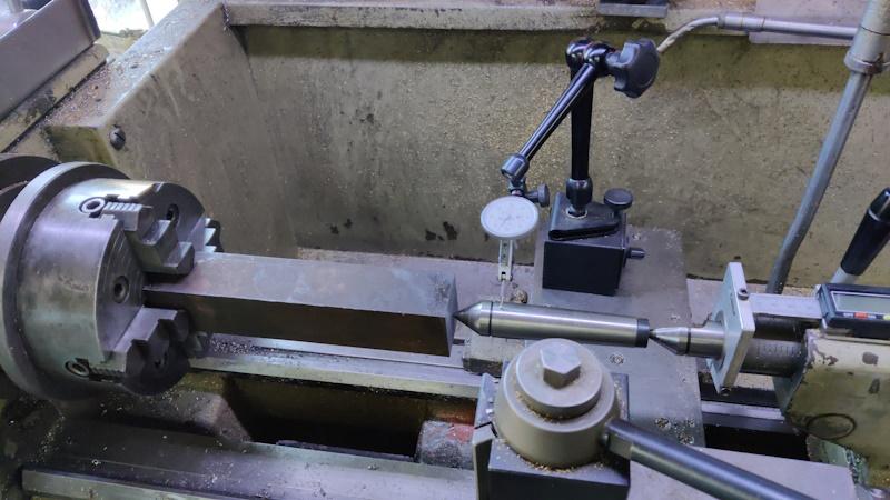
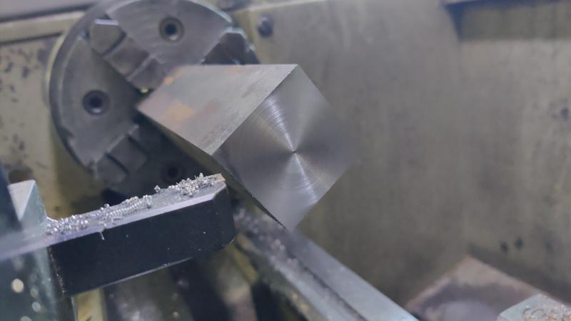
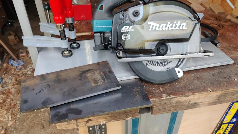
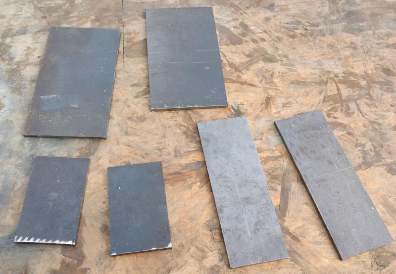
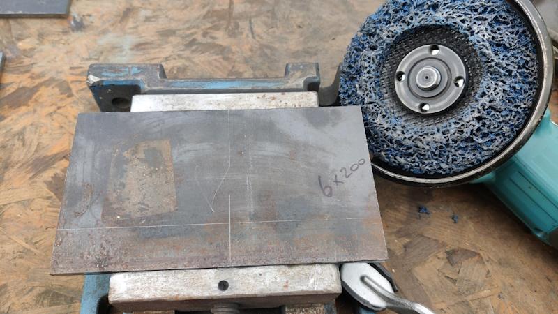
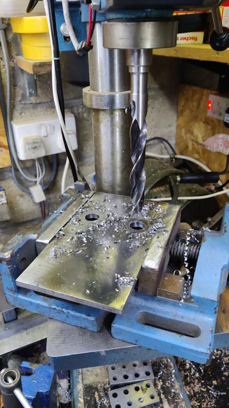
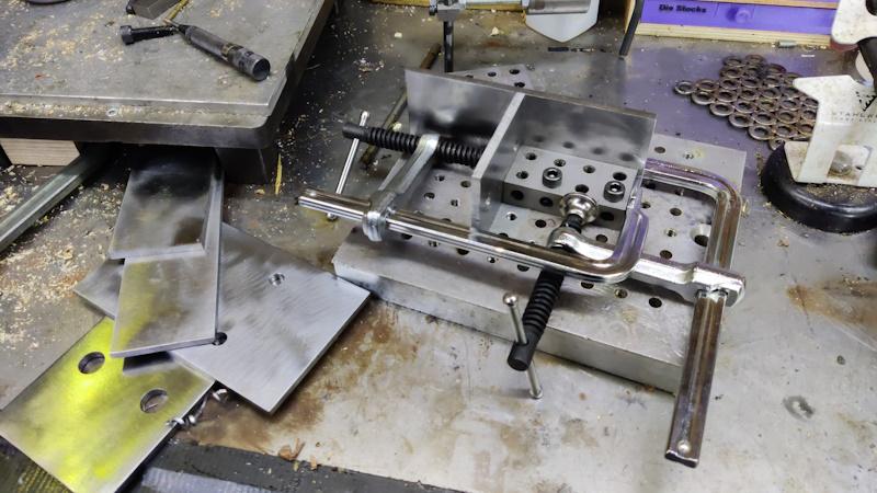
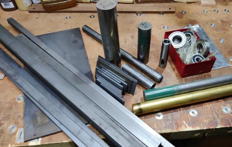
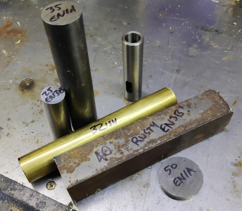
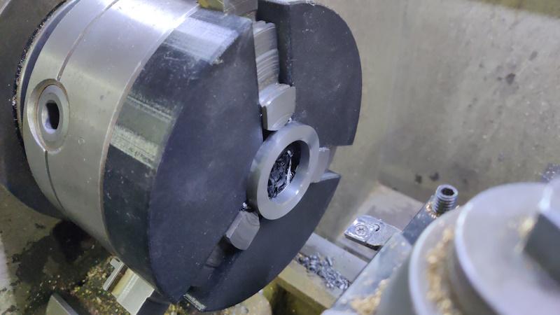
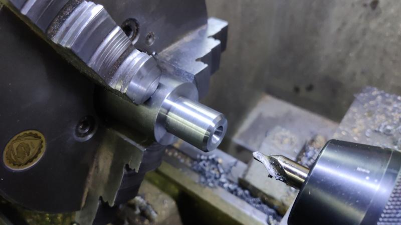
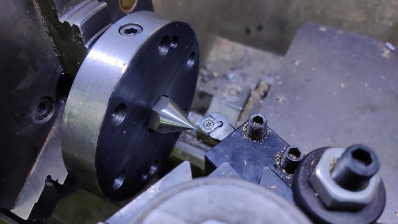
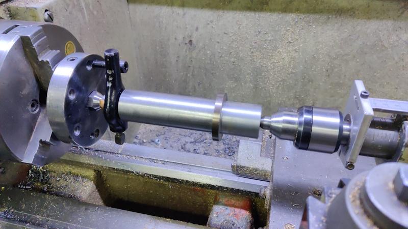
Step 1 of making chisel handles is thus: make a lathe (and some tools to use with it, probably starting with a spindle gouge). Doing this without buying anything could be a bit of a challenge, but I do have a very well equipped workshop and quite a lot of material of various different types, so it's probably not as challenging as it would be for someone with a more normal set of tools / materials. As a lot of the design will be based on what I find while rummaging through drawers, I probably won't model it in CAD: I'll just make it up as I go along and hope for the best.

I've never used a wood lathe before (I've never even seen a spindle gouge apart from on photos on the web), so there will be an extra challenge at the end in learning how to turn.

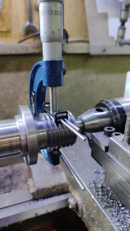
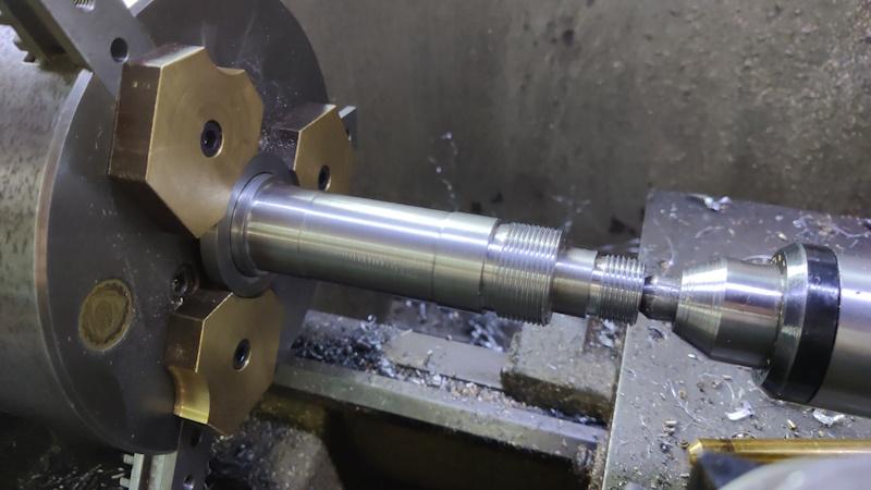
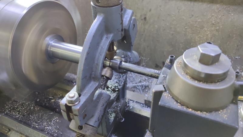
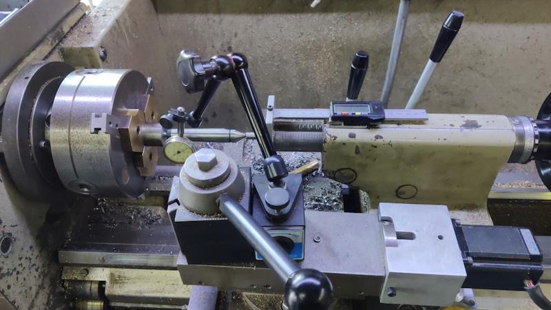
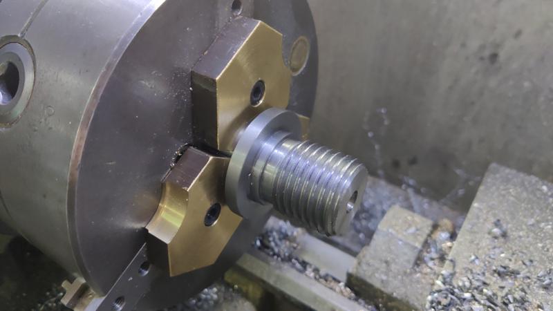
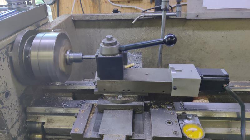
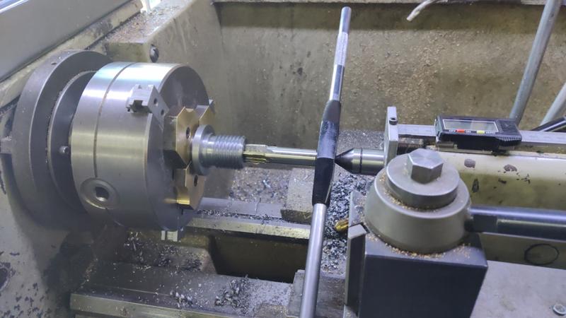
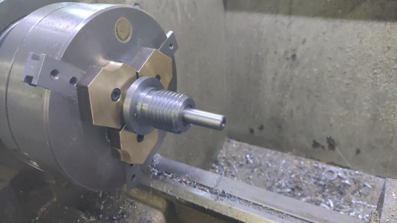
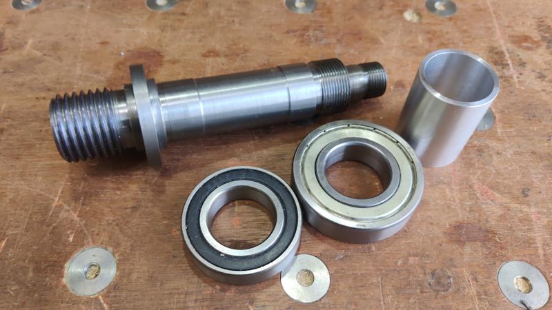
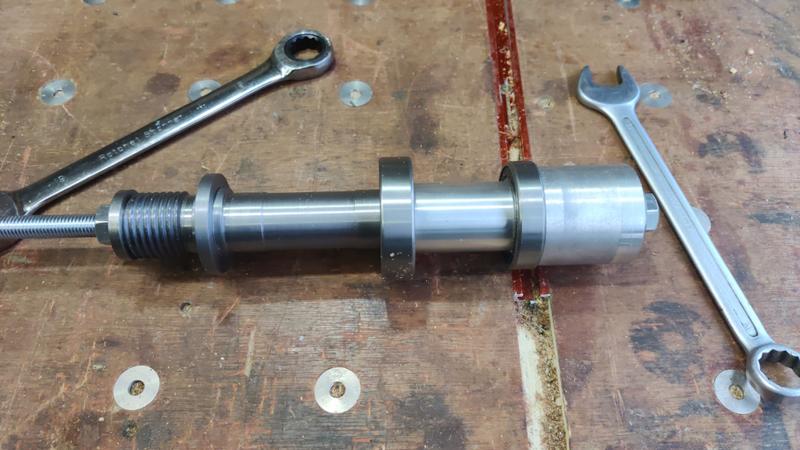
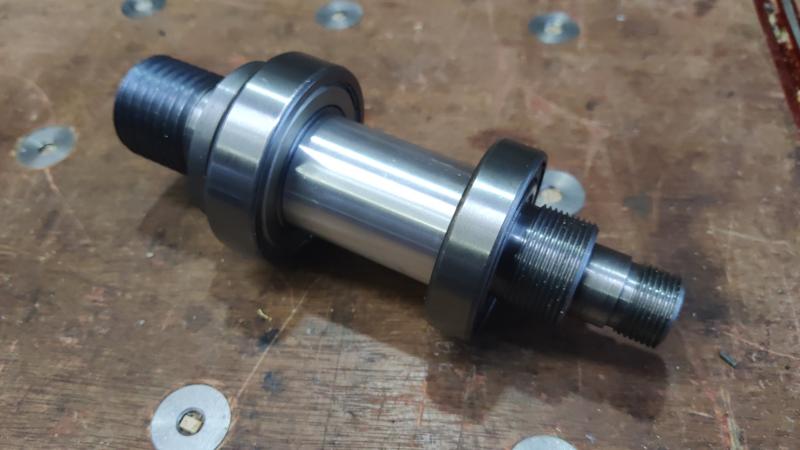
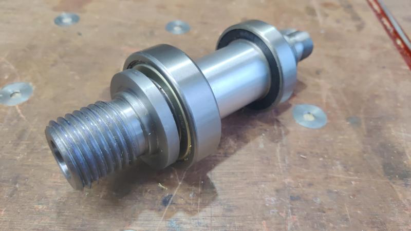
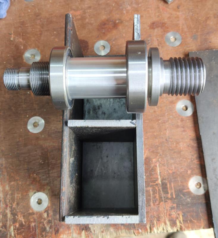
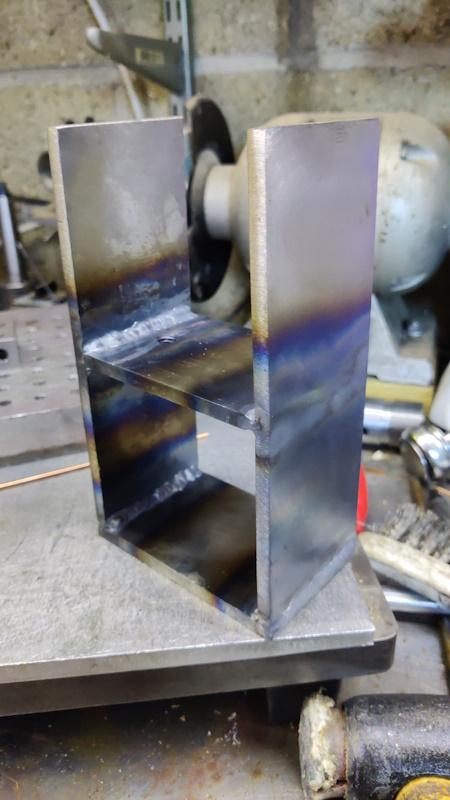
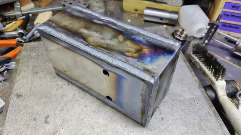
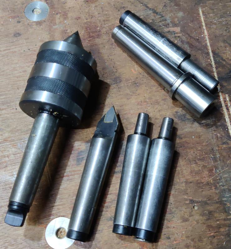
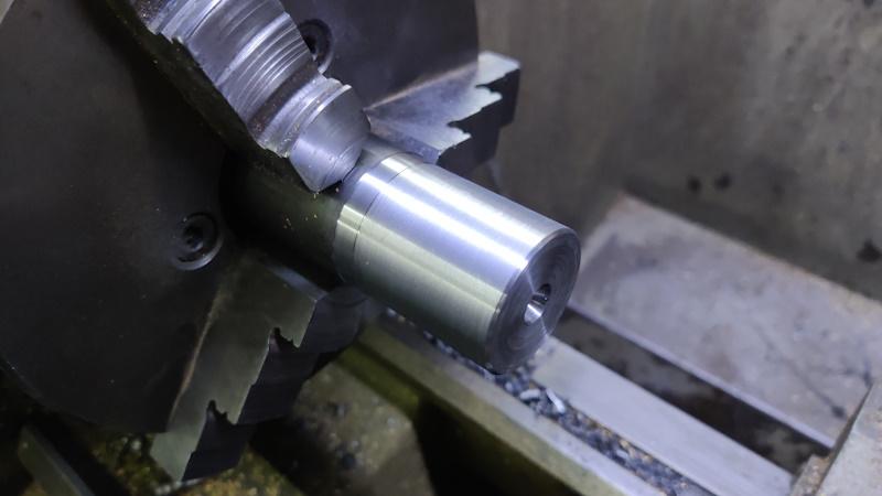
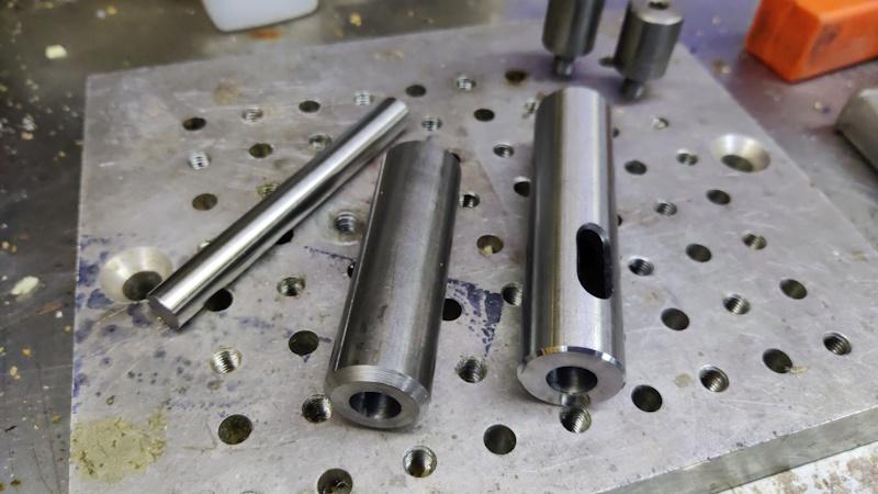
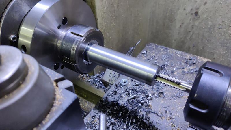
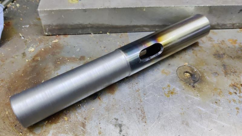
To make it a bit more challenging, I'd like the lathe to be useful for more than just these chisel handles, so I'm going to try to build some versatility into it. Also, the main reason I've never bought a wood lathe is lack of space to store it, so I'd like this to be easy to dismantle for storage. My initial thoughts on versatility are that I'll try to use Morse Taper sockets (probably MT2) in both headstock and tailstock and I'll turn a thread (probably M33×3.5) on the spindle so that I could potentially fit a standard chuck in future. I'm not really interested in "pure turning projects" - making projects like bowls and such like: I'm only really interested in turning for making parts for other projects (tool handles, drawer pulls and such like), so I don't want/need to make a lathe that can handle big diameters.

Suffice to say this project to make wooden chisel handles isn't going to involve much wood work (but that's good, because it's cold and wet outside and it's quite hard to do woodwork in my tiny workshop without having the door wide open).
 
The first thing to do was get a selection of material out from my various dumping grounds:

a_selection_of_material_800.jpg


There should be plenty in there to make something reasonably robust (I must keep reminding myself this is a wood lathe and not a metal one!), although I haven't quite figured out the tailstock yet.

There's a very handy Morse Taper 2 adaptor in that pile, with a straight outside shank (25.4 mm / 1"). Using that as a basis of the tailstock would make things quite straightforward but it would need to move backwards and forwards in something bigger than 25.4 mm diameter. There's plenty of round bar that is big enough, but it's all EN1A or brass (I've also got some EN24T ferreted away somewhere). I'm thinking I'll make a frame out of flat stock (for both headstock and tailstock) and that means welding the body together. As I understand it, EN1A and EN24T are both pretty terrible options for welding (and brass is right out), so I might need to think of an alternative. The brass would probably be quite good as a running surface for the sliding adaptor. One to ponder anyway. It's less of an issue for the headstock as that will run in some bearings so doesn't need to be welded to anything.

I also need to make a firm choice about the headstock and tailstock tapers. Most wood lathes seem to use MT2, so that seems the best option. However, I've got loads of MT3 tooling and about four "blank end arbors" in MT3 size (I was convinced I had some MT2 ones but I guess I used them all years ago). This is all the MT2 tooling I could find (I'm sure I've got a plain dead centre somewhere but I couldn't find it):

morse_taper_2_800.jpg


For the bed of the lathe, my current plan is to use a couple of bits of box section in parallel, with something welded across the ends to join them together. I'd leave a gap between the two bits of box section for bolts to go through to hold the headstock and tailstock down. I've got box section in several sizes: 25 mm, 30 mm and 40 mm sides, all with 2 mm wall thickness.

Some pondering needed now.
 
As a suggestion, why not try some London pattern octagonal handles if they'll fit into the scheme? Not too difficult to make with a basic lathe and some straight forward tools, but you need a smallish ferule to make them look effective. Matt at WH have chisels in stock with some of these handles - Rob
 
I think the chisel handle thing is a red herring. This project is about making a lathe.

From my limited experience, your bits of steel look a bit short and a bit lightweight for a lathe that is of any great utility..........but we won't really be able to comment until we've seen a drawing.
 
Woodbloke":efxjhxnu said:
As a suggestion, why not try some London pattern octagonal handles if they'll fit into the scheme? Not too difficult to make with a basic lathe and some straight forward tools, but you need a smallish ferule to make them look effective. Matt at WH have chisels in stock with some of these handles - Rob

Thanks Rob: that's worth a look too. I've yet to find a chisel handle shape I really like, so I'm sure I'll go through a few iterations & I'll probably try something like that. I've got some Ashley Iles dovetail chisels which are lovely & light when holding them by the blade and chopping, but when holding the handles for paring or whatever I find them a bit small for a comfortable grip. At the other extreme, the Narex 8116 chisels have big chunky handles that are great for paring but make the chisels quite heavy when gripping the blade and chopping.

Mike G":efxjhxnu said:
I think the chisel handle thing is a red herring. This project is about making a lathe.

Ssh, don't let the secret out :lol:

Mike G":efxjhxnu said:
From my limited experience, your bits of steel look a bit short and a bit lightweight for a lathe that is of any great utility..........but we won't really be able to comment until we've seen a drawing.

You might well be right. I don't really have a feel for how solid things need to be. I've seen lathes made out of plywood which will obviously be flimsier than this (but also possibly not that good). I'm not sure you're going to see much in the way of drawings if I just make it up as I go along. If I use that 6 mm plate as the basis of the frame & the 50 mm diameter bar as the spindle, I think it could be quite robust, but then I've no idea how robust a lathe needs to be for small diameter wood turning.
 
Yep. I immediately thought: a few 'andles out of unsuitable walnut :? *, this is not a wood project at all, it's bound to be about engineering. And sure enough.....

I shall be interested in your lathe design and build Dr A. You always do a first class job of everything, so this will be epic. Bear in mind, for wood lathes, that good ones are always heavy. Wood is always out of true and shakes the lathe about. Mine is heavy, but the stand is not heavy enough, and wood can shake it about until the corners are knocked off.

* walnut looks lovely and is great to work but I abuse my chisels by hitting them with wooden carving mallets or Thors, and walnut is not that robust in my experience. But will look lovely (at first) :oops:
 
Great project! I too am sure it will "turn out" well! :D

If you just wanted walnut chisel handles, traditional tapered octagonal ones are quick and easy to make and good to use.

But thinking about the lathe, how are you thinking of powering it? Treadles are very good and well proven, as thousands of wooden lathes will show.

Or you could put a pulley on the spindle of your other lathe and connect them with a drive belt...that would be ok wouldn't it?
 
AJB Temple":1pldixh7 said:
Yep. I immediately thought: a few 'andles out of unsuitable walnut :? *, this is not a wood project at all, it's bound to be about engineering. And sure enough.....

I shall be interested in your lathe design and build Dr A. You always do a first class job of everything, so this will be epic. Bear in mind, for wood lathes, that good ones are always heavy. Wood is always out of true and shakes the lathe about. Mine is heavy, but the stand is not heavy enough, and wood can shake it about until the corners are knocked off.

That's useful, thanks. I hadn't really thought about non-round wood shaking things up. It sounds like your lathe is bigger than I'm aiming for though so: is it that much of a problem with spindle work?

I'm sure it'll be fairly heavy anyway & I'll have the option of filling the box section with sand if I need it to be heavier. It needs to be light enough to carry around (for storage), although it would be fine if that is done in three pieces (headstock, tailstock, bed).

AJB Temple":1pldixh7 said:
* walnut looks lovely and is great to work but I abuse my chisels by hitting them with wooden carving mallets or Thors, and walnut is not that robust in my experience. But will look lovely (at first) :oops:

I hadn't considered the robustness. I guess I'll see how it goes & if the walnut doesn't work well I can try again in some other wood. It'll probably take me a few goes to get a shape I'm happy with anyway.

AndyT":1pldixh7 said:
Great project! I too am sure it will "turn out" well! :D

Groan

AndyT":1pldixh7 said:
If you just wanted walnut chisel handles, traditional tapered octagonal ones are quick and easy to make and good to use.

But thinking about the lathe, how are you thinking of powering it? Treadles are very good and well proven, as thousands of wooden lathes will show.

I'm sure a treadle lathe would be a possibility, but mine's going to have a motor! I did think about a treadle, but the main problem with it is the size of the lathe: it would have to have a base (rather than just getting fixed to my bench) and that would mean I'd need somewhere to store said base.

AndyT":1pldixh7 said:
Or you could put a pulley on the spindle of your other lathe and connect them with a drive belt...that would be ok wouldn't it?

It would probably be okay (assuming a speed increase from the pulley) & it would give me variable speed for free, but it would mean the wood lathe would have to sit in a very awkward place (and it would need a base).

I've got a couple of viable options for power. I've got a spare single phase motor from when I restored my horizontal bandsaw (and didn't think I was going to be able to recover the motor). I've also got a spare bench grinder. I've also got a less viable option in the form of a massive 3 phase motor, but that would definitely need a variable speed drive (which I don't have) and it's probably big enough to power a small car, so might be overkill for a small wood lathe 8-)

I'll probably use the bench grinder, with a pulley on the grinder shaft & another on the lathe spindle. The only issue will be if the one & only drive belt I've got isn't suitable, I might have to break my rule about not buying anything :o
 
Dr.Al":37a6ltzr said:
That's useful, thanks. I hadn't really thought about non-round wood shaking things up. It sounds like your lathe is bigger than I'm aiming for though so: is it that much of a problem with spindle work?

For normal spindle work it isn't an issue and as long as the lathe is robust and well bolted down, weight added to the stand if required you won't have any problems whatsoever. No need to take the corners off first or even for the wood to be square. I do it all the time with many different species, walnut is dead easy btw compared to lig vi for instance, just use a roughing gouge or skew to take it from square to round.

If you start with biggish lumps of misshapen logs, attempt offcentre turning or out of balance faceplate work then you have to be more carefull. If powered rather than treddle you're making then try to make it variable speed if possible as it's far more convenient in use.
 
Dr.Al":2z6qga1h said:
It probably won't surprise you to hear that this will probably be done in an overcomplicated way, but as usual: as long as I enjoy the process, I'll be happy.

Al, we are bothers from different mothers.

Gary
 
A pole lathe is all you need to make handles. There are designs that knock down and can be shoved away in a corner. Little metalwork skills required, just need to be able to put a pointy end on a bit of bar. The rest is simple woodwork. No electrons need be inconvenienced.

But don't let me stop you ...
 
Sheffield Tony":kshyjrqy said:
A pole lathe is all you need to make handles. There are designs that knock down and can be shoved away in a corner. Little metalwork skills required, just need to be able to put a pointy end on a bit of bar. The rest is simple woodwork. No electrons need be inconvenienced.

But don't let me stop you ...

All very true, but I reckon Al won't need much collective nudging from the Secret Society to make this lathe a computer controlled one, so he'll have the choice of 3D printing or automated turning, from the same design drawings... why else would he have shown us that "mock-up" handle back at the beginning? :D
 
I have thought about a pole lathe a few times but again the size (in use as well as storage space for some of the bigger bits) put me off. Also I think some of the finer stuff (drawer pulls and such like) would be a lot easier with a powered lathe. I'm doing a two-day pole lathe stool making course thing in May (birthday present from last year from my brother), which should be fun, but I think for now I'd rather have a compact motor-driven thing for the workshop.

Oh, and no Andy, this won't be computer controlled or anything like that. I do enough computer programming at work to not really want to make that a major part of my hobby!
 
There’s a whole lot of chair/stool interest at the moment which is very interesting for the rest of us. Looking forward to hearing all about the pole lathe experience Al.
So is this to be about the size of a watch/clockmakers lathe?
 
Dr Al - computerisation aside, probably is worthwhile having electronic speed control on your lathe. Mine doesn't but I wish it did.
 
Cabinetman":27k2ctg6 said:
There’s a whole lot of chair/stool interest at the moment which is very interesting for the rest of us. Looking forward to hearing all about the pole lathe experience Al.

This is the course I'm doing in May: https://www.touch-wood.co.uk/product/co ... king-stool

CabinetMan":27k2ctg6 said:
So is this to be about the size of a watch/clockmakers lathe?

I'd guess it'll be a little bigger than that, but I'm not really sure yet (did I mention I was making it up as I go along?!). Lengthwise it'll be quite flexible as the bed will be box section, so it should be quite easy to make an extended bed if required. I'll probably aim for 250 to 300 mm between centres, but I might go shorter initially. I'm not sure on centre height. Definitely won't be more than 150 mm (12" swing for the American market!), but I'll probably go for less: perhaps 100 mm?

AJB Temple":27k2ctg6 said:
Dr Al - computerisation aside, probably is worthwhile having electronic speed control on your lathe. Mine doesn't but I wish it did.

I think that's a good idea, but that'll be mark 2 as it won't be possible without buying stuff. The motor will be connected via some sort of drive belt, so it should be trivial to swap the motor out to something suitable for a VSD in future.
 
Interesting about swing size in the US, I didn’t know that.
Presumably you will be using a multi set of pulleys? Admittedly I don’t do much turning but the 4 speeds are ok for me, can’t remember the last time I changed speed at all tbh. Will have a look at that course later.
Ian
 
Cabinetman":3b7138v8 said:
Interesting about swing size in the US, I didn’t know that.

It might not be true for wood lathes to be honest. For metal lathes the English like to refer to them by the height of the centre above the bed whilst the Americans like to refer to them by the biggest diameter workpiece they can hold (i.e. double the English number). I just assumed the same was true with wood lathes.

Cabinetman":3b7138v8 said:
Presumably you will be using a multi set of pulleys? Admittedly I don’t do much turning but the 4 speeds are ok for me, can’t remember the last time I changed speed at all tbh. Will have a look at that course later.
Ian

I haven't quite decided on pulleys (partly as a result of the expectation that I might upgrade to variable speed in the future). I think what I'll do for now is plan to have one position for a pulley but put it on the end of the spindle so the whole pulley can be swapped out if required. That does mean it'll take a bit longer to change speeds (loosen drive belt, undo and remove pulley nut, slide pulley off, slide new pulley on, tighten everything), but it'll mean that the spindle shaft can be quite a bit shorter, which will make it a lot easier to make.

If that ends up being a massive pain, I can always make the motor shaft have multiple pulleys on and switch speed at that end of the drive belt (although the disadvantage of that will be having to slide the motor longitudinally).

As I said, I'm making this up as I go along, so it's entirely possible it won't work at all well. I'm hoping it'll at least work well enough to help me decide whether I want to have a lathe available. If I do and this one doesn't work, I'll buy a "proper" one :)
 
John Brown":2203i55w said:
Or you could pop up the road to Stinchcombe and take my surplus Arundel J4 junior off my hands for £100...

If I'd known about that before I'd started, I might well have done that! I've never heard of that lathe, but I'll bear it in mind if this all goes wrong...
 
The first job of this afternoon was to assemble and roughly cut to length a subset of the materials I dragged out yesterday:

material_subset_800.jpg


I've decided to make the spindle out of 35 mm EN1A. That has the advantage of being closer to the 30 mm inner bore of the bearings I've got (and hence I won't have to turn as much material away) and also the M33×3.5 thread I'm planning to put on the working end (for a possible future chuck purchase). The disadvantage is that a chuck won't really have much of a surface to bear against (because 35 mm isn't much bigger than 33 mm), but I've got a plan to help sort that out.

I started with the spindle. The length is a bit arbitrary, but hopefully should be long enough for chuck section, bearing, gap, bearing, two nuts to hold spindle in place, pulley, nut to hold pulley in place. This is all a bit haphazard, but I've got plenty of 35 mm EN1A (another reason for choosing it) so I can always have another go.

The first job was to take the slice of 50 mm EN1A, skim the faces (using a 3D printed chuck spider to help hold it a bit more easily) and drill then bore a hole that's about 34 mm diameter. I wasn't too worried about the actual size here as long as it was less than 35 mm and more than 33.5 mm.

turning_50mm_ring_800.jpg


The first job for the actual spindle was to put the spindle in the chuck, face one end, reduce the outer diameter to 20 mm for a bit and stick a centre drill hole in the middle of it.

turn_and_centre_spindle_rear_end_800.jpg


The reduced diameter will eventually form the surface that the pulley rests on, but for now I just wanted it somewhere near the right size.

I then flipped it over and did a similar thing on the other end:

rough_turn_and_centre_spindle_outer_end_800.jpg


The first diameter reduction was to 33.5 mm for 37 mm length. That'll eventually become the M33×3.5 thread (for 33 mm) and then a plain 33 mm register after that for 4 mm. That's based on a document I found online for a typical chuck mount. Without a chuck, I can't really confirm whether that's right or not. The second (narrower but shiny) bit was made very carefully (lots of micrometer measurements) to be slightly larger than the bore I made in the 50 mm ring.

With that done, the spindle went in the freezer and the ring went in the kitchen oven on maximum temperature (about 250°C) and they were left for a bit while I got on with the next bit.

The next bit was working on the (80 mm long) 25 mm EN3B section, which was drilled through 8 mm and then drilled and reamed 12 mm to a depth of 60 mm. The reamed hole is overkill (it's a lots-of-clearance hole for an M10 thread so it really doesn't need to be reamed!), but reaming it was intended to help with one of the next jobs. The part also got a heavy chamfer on the end with the 12 mm hole.

I also mounted the Morse Taper adaptor thing (which has a 25.4 mm / 1" outer diameter) in a collet chuck and drilled, bored and reamed a 12 mm hole in the bottom of that. The boring operation was because the adapter was quite hard and the drills didn't seem too happy: I figured a carbide boring bar would cope better. This part also got a heavy chamfer.

drilled_and_reamed_tailstock_bits_800.jpg


The other piece you can see in that picture is a bit of 12 mm silver steel, which is ground to a very accurate size. That went into the 12 mm hole and forced the two pieces to be aligned. Then it was TIG time (something I haven't done for a while):

tig_time_800.jpg


The first tack didn't go at all well, so I turned the Argon on (D'Oh!) and tried again and things went much better second time round. It was quite awkward welding as I had to do it in small sections, but it's looking okay to me so far:

tigged_800.jpg


That was then left to cool down and by now I figured that the spindle bits were probably somewhere near hot/cold, so I went back into the house and quickly joined them together (with a bit of mallet-based persuasion for the last bit):

hopefully_tight_800.jpg


That's now ready for turning between centres, at which point I'll know how good the fit of the wider bit was. That larger diameter bit is only forming a register against which a chuck would rest, so it's not going to be put under much strain once in service, so it should be fine.

Before turning between centres, I went back to the tailstock spindle. I mounted it in the collet chuck and skimmed the outside diameter of the EN3B bit to make sure it was concentric and a smaller diameter than the adapter bit. I then drilled out the hole to 8.5 mm and started tapping M10 left-hand:

tapping_800.jpg


I went in far enough that I felt sure the thread had started properly, then took the tailstock spindle out of the chuck, put it in the vice and finished tapping by hand. I was a bit nervous about breaking the tap as I didn't have a spare of either the tap or the Morse taper adapter. Thankfully all went well and the tailstock spindle is (almost) done:

tailstock_spindle_done_800.jpg


The last job on that will be to mill a slot in the EN3B bit for a pin that will stop it from rotating (when drilling or whatever).

Now back to the headstock spindle. I put the three-jaw chuck back on the lathe, mounted a soft centre and took a very light cut to make sure it was definitely running true to the machine:

turning_soft_centre_800.jpg


The spindle could then be mounted between centres ready for turning.

ready_for_turning_spindle_800.jpg


That felt like a good place to stop for the evening: tomorrow I'll get on with turning the spindle to size (whatever that size may be!)
 
Dr.Al":2qd18acq said:
John Brown":2qd18acq said:
Or you could pop up the road to Stinchcombe and take my surplus Arundel J4 junior off my hands for £100...

If I'd known about that before I'd started, I might well have done that! I've never heard of that lathe, but I'll bear it in mind if this all goes wrong...
I've no doubt yours will be better, at least for your purposes!
 
So this lathe is going to be easily dismantled for storage ;) :eusa-think:
So putting it in the car and taking it on holiday would not be impossible :)
 
Andyp":1tgyob9l said:
So this lathe is going to be easily dismantled for storage ;) :eusa-think:
So putting it in the car and taking it on holiday would not be impossible :)

Oi, stop that right now! :o :lol:
 
Turning the spindle took a lot longer than I expected. We left the "action" yesterday with the spindle mounted between centres on the lathe. I started by roughing out the shape of the spindle. Here's a blurry action shot:

1001_blurry_action_shot_800.jpg


When the shape was roughed out, I swapped to a high-speed steel tool with a rounded profile. This tool can take extremely fine cuts. I used this to bring the two bearing surfaces to size (finishing one before starting the next):

1002_turning_bearing_register_800.jpg


As I approached the final dimension, I was checking after each cut. I had the top slide set at about 5.75° to the axis of the lathe, which results in a 10:1 ratio of top slide feed to in-feed. That means that moving the top slide forward 0.02 mm moves the cutter forward about 0.002 mm. Being able to do that is very handy when you're creeping up on a critical dimension (as long as the tool can take fine cuts, which this one can).

1003_checking_size_800.jpg


The reference book I was using suggested the shaft size for a 30 mm bearing should be between 30.002 and 30.011 mm. This was the final measurement on one of the registers:

1004_hopefully_ok_800.jpg


At that point I just had to hope that I'd done it (and measured it) right and that all would be well when the bearings were fitted.

Next up was the thread for the chuck. I've never cut a thread as coarse as 3.5 mm pitch and I've got nothing to check it with, so I'll just have to hope it turns out okay.

After rearranging the change gears on the lathe (I can only go up to 2 mm pitch with the "standard" arrangement), I did a very light cut to check the pitch came out okay:

1005_starting_chuck_thread_800.jpg


I then kept taking light passes (feeding in with the top slide, which was set at 60°) until the over-wires measurement was slightly under nominal for M33×3.5:

1006_checking_over_wires_800.jpg


The spindle could then be removed from the centres. There's still lots to do, but nothing that could be done with that set-up. With the spindle roughed out, I could measure the distance that would be between the inside faces of the two bearings. A spacer between them will make it much easier to assemble, so I rummaged around for a while and found a bit of aluminium that was (just) big enough. After facing it in the lathe, I drilled a hole, going up through the sizes until I reached my biggest (25 mm) drill bit and reminding myself of why I hate turning aluminium:

1007_drilling_aluminium_800.jpg


Once I'd run out of drill bits, I used a boring bar to enlarge the hole to a bit over 30 mm. The dimension isn't critical as long as it goes over the bearing surfaces.

1008_boring_aluminium_800.jpg


That piece was parted off to length and then it was back to the spindle. I fitted my soft jaws to the chuck and bored a pocket in them of the right size to hold the widest diameter of the spindle. I then mounted the spindle with the nose facing into the chuck and turned a couple of threaded bits on the outer end.

1009_turned_outer_threads_800.jpg


The left hand one of those will be for a pair of nuts to hold the spindle into the headstock. The right-hand one will hold the pulley in place. Given that I'll be making the nuts, I decided to make both of them 1.5 mm pitch as I have some insert tooling for cutting 1.5 mm pitch threads.

With the threads cut, I fitted the fixed steady, running on the surface that the pulley will sit on (I didn't want to run it on the bearing surfaces in case it damaged them). I could then remove the tailstock centre support and drill a bit over half way through the spindle. I drilled 10 mm then 13 mm and then bored to 14.6 mm (or thereabouts), which is a little over the small-end diameter of a Morse Taper 2.

1010_setup_for_drilling_from_rear_800.jpg


1011_boring_from_rear_800.jpg


The next job was to align the top slide to the correct taper for MT2. While I had the soft jaws in the chuck, I mounted a bit of scrap and turned a short centre on the end. I could then mount a bit of MT2 tooling between headstock and tailstock and use it to align the top slide. Before doing that, I swapped the top-slide hand-wheel for my home-made top-slide motor (which uses a DivisionMaster controller configured such that 1° is 1 mm). The top-slide motor allows very fine control of position and very smooth motion, which is nice when cutting tapers as it leaves a good finish.

1012_aligning_top_slide_800.jpg


There was an intermission during this period where I dropped the Woodruff key that connects the top slide leadscrew to the handle and spent about an hour rummaging through swarf to try to find it again.

With the top slide aligned, the spindle could be mounted in the soft jaws (which were machined in place to have a 30 mm bore: machining in place guarantees that they'll hold the spindle concentric with the bearing surface).

1013_mounted_spindle_800.jpg


After drilling and boring to 14.6 mm as before, I used the top slide motor to bore the Morse Taper, gradually increasing diameter until the outside diameter was about right according to the reference dimensions.

1014_cutting_morse_taper_800.jpg


I happen to have a Morse Taper 2 reamer, so I pushed that into the spindle and turned it a couple of times as I figured it would probably improve the accuracy compared to my top slide alignment attempt.

1015_reaming_morse_taper_800.jpg


I then grabbed a bit of Morse Taper 2 tooling I had and shoved it into the spindle. It didn't want to come out again, which I saw as a good sign!

1016_checking_morse_taper_800.jpg


Once the MT2 tool was removed (with a bit of 12 mm bar inserted from the rear of the spindle and hit with a hammer), it was ready for assembly and finally finding out how I did with the bearing surfaces:

1017_spindle_ready_for_assembly_800.jpg


I don't have a press of any kind, so the only way I could think of pushing the bearings on (remember that the bearing surfaces were turned to interference fits) was with a bit of M12 threaded rod and a few hastily turned washers / spacers:

1018_assembly_method_800.jpg


I was extremely relieved when the bearings slid home!

1019_spindle_done_1_800.jpg


1020_spindle_done_2_800.jpg


That's it for today. I need to have a hard think about how on earth I'm going to make headstock and a tailstock and how I'm going to get the requisite holes in them aligned. That feels like it's going to be quite a challenge, especially given the amount things are likely to distort when I weld them together.
 
Cor indeed!
I've nothing to add but I'm enjoying the ride.
 
Today I've been working on two different jobs in parallel. I started work on the tailstock body as the first jobs on the headstock body were going to be noisy and I was out in the workshop a bit too early to feel comfortable waking the neighbours up. Once it had got to 11am, I started on the headstock body and focused on that, although there were a few times when the headstock body needed to cool down and I switched back to the tailstock body.

I'll try to write this up as if I did them one at a time though as I think it'll be easier to follow.

The first job on the tailstock body was to mark a centre point on each end and then mount it in the four jaw chuck on the lathe. A dial test indicator was used to get that centre point bang on centre.

1101_clocking_square_section_800.jpg


I then faced the end (taking very light cuts and with the lathe running slowly as that bar is sticking out a very long way from the chuck!)

1102_face_end_800.jpg


Once it was faced, I spot drilled a centre mark and then worked my way through my drill bits. I started at 10 mm, drilling as deep as I could:

1103_start_drilling_800.jpg


I then went up through my big drill bits, which I've got in steps of 3 mm, drilling as deep as possible with each of 13 mm, 16 mm, 19 mm, 22 mm and finally 25 mm:

1104_biggest_drill_bit_800.jpg


I'd recently sharpened all of those drill bits except the 22 mm one and it was quite noticeable how much harder it was to drill with the 22 mm one, so I stopped and sharpened it before continuing! The first section of drilling was quite easy going (up to the depth of the last drill bit), but each drill bit was a bit longer than the last, so the last bit was very slow going as the drill bit was removing the full diameter.

Unfortunately, even my massive 25 mm drill bit wasn't long enough to go all the way through, so I'll have to drill in from the other side. I don't think it'll be the end of the world if the two holes aren't spot-on concentric as only the first half-ish of the hole is critical.

Once I'd run out of drill bits, I used a big boring bar to bore as deep as I could (a bit over half way). I enlarged the hole gradually until it was a bit under 30 mm with a CCMT tip:

1105_rough_boring_800.jpg


Then switched to a polished CCGT tip and took a single light pass. The diameter isn't that critical as I'll be sizing the component that goes in that hole to fit the hole, but it's about 30 mm.

1106_fine_boring_800.jpg


That's all I've done so far on the tailstock body. Next job will be to turn it round and drill / bore some features from the other end.

The headstock is going to be made from 6 mm steel plate (mainly because I've got quite a lot of it). I'd been pondering on how to cut the plate up as it was too big for my bandsaw. I've got a cheap ebay plasma cutter, which would cut through it like a knife through butter, but it would leave a rather shabby edge (although that's probably partly down to my lack of skill rather than an inherent flaw of the tool!). I've also got a Makita cordless metal-cutting circular saw, which I've never used on anything thicker than about 3 mm. The manual says it can cut thicker, so I thought I'd give it go.

1107_chopping_6mm_steel_up_800.jpg


Wow. It went through that 6 mm plate at the sort of speed I'd expect a "normal" circular saw to cut through hardwood. It also left a fairly clean edge at the end and most of the swarf got caught in the hopper thing. I'm very, very impressed.

With the plates cut roughly to size, I could have a look at the general arrangement:

1108_general_arrangement_800.jpg


Obviously the spindle will eventually go through the middle of the headstock, but I thought it was instructive to lie it on top to show roughly where it will end up. Incidentally, I've settled on a centre height of about 125 mm (so the maximum diameter workpiece that could be "swung" would be 250 mm). I can't see me ever needing to turn anything that big, but at least it'll give plenty of room for me to make the tool support as big as I like.

With all the bits cut to final size, I had a lot of mill scale to remove:

1109_mill_scale_800.jpg


I used one of these "non-woven preparation wheels" to remove the scale:

1110_mill_scale_before_800.jpg


They work really well, removing the scale easily without taking away much steel so they leave a good finish and a flat surface:

1111_mill_scale_gone_800.jpg


The only disadvantage of them is that they only really work with a relatively slow running speed, so they need a variable speed grinder. That meant using the cordless one, which is quite heavy and unwieldy and chews through batteries (although it is definitely very convenient).

With the faces all cleaned up, I gave the ends a touch up with a flap disk, this time using the mains grinder:

1112_flap_disk_ends_800.jpg


With that done, the bits are nearly ready to be welded together:

1113_all_done_800.jpg


A quick test fit to confirm everything looks okay:

1114_test_fit_800.jpg


Before starting welding, I thought I'd drill a few strategically located holes. Two 10 mm ones on what will be the rear face, two 16 mm ones on what will be the front face and a couple of M10 tapped holes in the inner shelf. The tapped holes will probably never get used, but if I decide I need a bit more weight, I can fill the bottom pocket with sand through the tapped holes (after plugging the holes in the front and rear faces) and then put some screws in the holes to stop the sand coming back out. As the location of the holes wasn't especially critical, I drilled them with the pillar drill (as it's a lot quicker than setting up the milling machine):

1115_drilling_holes_800.jpg


I used a simple jig that I made a few years ago (basically just some aluminium with lots of drilled holes and lots of tapped holes) to help hold things square:

1116_jig_for_welding_800.jpg


With that done, there was nothing left but to get on with the "hot-melt gluing", first the inner frame:

1117_inner_frame_800.jpg


Then, after a quick touch-up with a flap disk, the front and rear faces were welded on:

1118_all_welded_800.jpg


Once it had mostly cooled down, the angry grinder came out one more time to clean up the welded surfaces:

1119_cleaned_up_800.jpg


Sorry for the out-of-focus photo.

That's it for now. The next job on the headstock will be the slightly daunting task of boring the holes for the bearings and figuring out how to retain said bearings in the headstock.

My current plan is to make some aluminium retaining pieces that go over the bearings on the inside of the headstock and screw to the front and rear faces. With one holding each bearing, there should be no way for the bearings to shift. The spindle shouldn't come off the bearings (as they were an interference fit), but I'll add a nut to the back of the spindle just to be sure.
 
Most of what you are doing is way over my head Al. Do you have a plan/sketch of what this will look like when finished?
 
Andyp":2tp3zkxu said:
Most of what you are doing is way over my head Al. Do you have a plan/sketch of what this will look like when finished?

No: that probably would have been a good idea :lol:

I'm very much making this up as I go along. I'm sure that's going to cause problems later, but I'll just have to try to deal with them as they come up.

I might have a go at a CAD model at some point (i.e. measure what I've done and see if it helps with later things).
 
The last time I caught up with this thread, you mentioned aligning the bearing holes after welding.
I meant to mention the line boring them on the lathe after welding is probably going to be easier.

Bob

On the subject of line boring, Snowball Engineering on youtube does quite a bit of this when repairing agricultural machinery. He is a very talented and resourceful guy taking on abused machinery and fixing it up with great results. An interesting watch during downtime!
 
9fingers":2e1vluyr said:
The last time I caught up with this thread, you mentioned aligning the bearing holes after welding.
I meant to mention the line boring them on the lathe after welding is probably going to be easier.

Bob

On the subject of line boring, Snowball Engineering on youtube does quite a bit of this when repairing agricultural machinery. He is a very talented and resourceful guy taking on abused machinery and fixing it up with great results. An interesting watch during downtime!

Thanks Bob. I've never tried line boring (which I think is the same thing as what I've always known as boring between centres: clamping the workpiece to the cross slide and using a rotating boring bar). It probably would have been the best way to make the tailstock thingy (although as I said I don't think that concentricity of the two ends is **that** critical in that case). I'll have to do a bit more research about it (I don't really know what a between-centres boring bar looks like or how you adjust the cut depth.

For the headstock, I think there are easier ways given that it's only about 75 mm thick (from memory) and that I've (deliberately) chosen a 125 mm centre height. We'll find out at the weekend whether my plan works!
 
Cabinetman":2n1150dw said:
Crikey I make things up as I go along, but I do nearly always have a bit of a sketch!
As was said way beyond my ability with metal, but fascinating all the same.
Ian

:text-+1:

Totally agreed the precision machining is facinating to watch and way beyond anything I could hope to achieve.
 
Back
Top