• Hi all and welcome to TheWoodHaven2 brought into the 21st Century, kicking and screaming! We all have Alasdair to thank for the vast bulk of the heavy lifting to get us here, no more so than me because he's taken away a huge burden of responsibility from my shoulders and brought us to this new shiny home, with all your previous content (hopefully) still intact! Please peruse and feed back. There is still plenty to do, like changing the colour scheme, adding the banner graphic, tweaking the odd setting here and there so I have added a new thread in the 'Technical Issues, Bugs and Feature Requests' forum for you to add any issues you find, any missing settings or just anything you'd like to see added/removed from the feature set that Xenforo offers. We will get to everything over the coming weeks so please be patient, but add anything at all to the thread I mention above and we promise to get to them over the next few days/weeks/months. In the meantime, please enjoy!

Dr Al's Latest Folly

I'm now wondering how you are going to cut an internal morse taper on the spindle and whether line boring* is going to be the answer?

* New term to me too. Still learning!

EDIT - I've now looked back and spotted a bit I'd missed. Sorry! :oops:
 
After getting a few comments asking about what I was expecting the lathe to look like once finished (answer: I'm not really sure as I'm making it up as I go along), I thought it probably would be a good idea to do a CAD model of the bits I've made so far and use that model to design some of the other bits I need to make.

I'd avoided a CAD model thus far as I'm constraining myself to use stuff that I've got lying around. Designing stuff entirely in CAD runs the risk of using stock sizes or bearings that I don't have. However, I've got far enough through the build that a lot of the major components are built, so if I work around those components, I can knock up a CAD model and hopefully won't end up designing anything that I can't then make.

With that in mind, a bit of CAD time came up with this model of the headstock and tailstock:

1301_cad_model_overview.jpg


The triangular-ish frame underneath the square-section tailstock body is very much in question: I doubt it'll look like that in the end. However, I wanted something for the model not to look like the tailstock was floating in space.

This is a top view of the headstock:

1302_cad_model_headstock_top_view.jpg


The silvery "nut" on the left holds the bearings onto the spindle (not that I think there's much chance of them coming off). The sandy coloured nut on the far left holds the pulley onto the spindle. The hole through the middle of the spindle is a new addition (i.e. I still need to drill it!) - that's there so I can shove a tommy bar through the hole when I'm tightening the nuts or a chuck onto the spindle.

The two green plates (which will be aluminium) hold the bearings (and hence the spindle) into the headstock. The right-hand plate will be permanently fixed to the headstock: the through hole will be big enough to allow the smaller bearing all the way through, but small enough to stop the bigger bearing from passing. It'll stop the spindle from moving to the left.

The left-hand green plate will be made in two pieces (hence the counterbored holes in the top to hold the pieces together). The bottom half will be dropped into the headstock before fitting the spindle and then lifted up and screwed to the top half. It's deliberately designed not to be flush with the headstock face (i.e. there's a gap on the left) so that tightening up the screws that will hold it into the headstock will apply a bit of pre-load to the bearings (which might or might not be a good thing: I don't really know anything about bearings). The left-hand green plate will stop the spindle from moving to the right, so the two plates should hold the spindle in the headstock.

This is a cross-section of the whole model:

1303_cad_model_cross_section.jpg


This is a cross-section of the headstock, which perhaps shows the retention of the bearings a little better:

1304_cad_model_headstock_cross_section.jpg


The eagle-eyed among you will note that I've alternated between modelled threads (e.g. on the spindle) and "cosmetic threads" (on the nuts). Normal practice in CAD modelling is to use cosmetic threads, but I wanted to have the chuck thread modelled so I thought I might as well model all the threads on that part.

This is a cross-section of the tailstock:

1305_cad_model_tailstock_cross_section.jpg


The tailstock spindle (or whatever you'd call it) rides in a brass bush. The reason for that brass bush is that I figured it would be a lot easier to machine an accurate bore in a relatively short length of (nice to machine) brass bar (which will fit into the headstock) than in a very long overhanging bit of EN3B. In the top of the tailstock spindle, there's a slot (which I haven't machined yet) for an anti-rotation screw - this screw will be inserted into the top of the tailstock through the hole you can see in the middle of the image.

The threaded tailstock screw will have an M10 left-hand thread machined along most of its length. I don't have an M10 left-hand die, so I'll have to cut that long thread on the lathe. Turning the hand-wheel clockwise will make the tailstock spindle thing extend. Turning it anticlockwise will make the tailstock spindle retract and when it is fully retracted, the end of the tailstock screw should push on the end of the Morse Taper tool and make it pop out of the tailstock.

It undoubtedly would have been better to use a trapezoidal thread on the tailstock, but I don't have any suitable taps so the M10 thread will have to do.

There's a bearing in the right-hand end of the tailstock. That's probably gratuitous for a tailstock screw, but I've got one of an appropriate size, so why not? I'll be machining the pocket for the bearing with a different set-up to the other bore, but I don't think the concentricity of the screw thread is that critical, so I think it'll be okay (famous last words!)
 
Thanks Al, makes a lot more sense now.

As far as alignment of head and tail stock are concerned. A flippant suggestion perhaps, if you can’t make it accurate* then make it adjustable.


*I am sure you can and I’ve no idea how to make one or both pieces adjustable.
 
Andyp":2jw8iqwv said:
Thanks Al, makes a lot more sense now.

As far as alignment of head and tail stock are concerned. A flippant suggestion perhaps, if you can’t make it accurate* then make it adjustable.


*I am sure you can and I’ve no idea how to make one or both pieces adjustable.

I've been thinking about that a lot and I certainly agree that adjustable is a good way of getting round inaccuracies. To be honest, I'm not completely sure how I'll sort it out yet: there are a few degrees of freedom (Y, Z, pitch & yaw). X is intended to be adjusted (sliding the tailstock along) and roll is either a combination of Y & Z or just the rotation of the spindle, depending on how you look at it.

I think I can get the Z height (height above the bed) of the two parts the same & if I do that right, the pitch will be okay too. Worst case, I can make the bed mounting fairly loose (i.e. able to be moved back & forth & twisted). It would be nice to have head & tail stock "automatically" line up though, so I'll see what I can figure out.

I also need to keep reminding myself that this is a wood lathe & for most purposes it doesn't need to be anywhere near as accurate as a metal lathe would have to be :)
 
In case it's any help, my cheap Taiwanese Axminster lathe has the tailstock height fixed (but possibly alignable by filing or shimming).

To adjust laterally, the round bar which forms the bed has a long straight strip bolted along it, underneath. The tailstock clamp tightens onto this strip. Where it makes contact, there's a grub screw. You can turn this in or out to slightly rotate the clamp, and so shift a centre in the tailstock until it lines up with another one in the headstock.

I'm sure you will work out some sort of adjustment that will work on your bed.
 
This is probably as really stupid question, but my over-the-road neighbour only had a metal working lathe, but seems to happily turn wooden things on it. Not standard lamps or anything, but definitely he'd do chisel handles. Is it just the challenge of making the thing from scratch?
 
AndyT":2k0lxmcv said:
In case it's any help, my cheap Taiwanese Axminster lathe has the tailstock height fixed (but possibly alignable by filing or shimming).

To adjust laterally, the round bar which forms the bed has a long straight strip bolted along it, underneath. The tailstock clamp tightens onto this strip. Where it makes contact, there's a grub screw. You can turn this in or out to slightly rotate the clamp, and so shift a centre in the tailstock until it lines up with another one in the headstock.

I'm sure you will work out some sort of adjustment that will work on your bed.

Thanks Andy, that's useful. I think I'll put off thinking about it until I'm much, much further into the build, but that description will be very handy when I do get to thinking about it.

SamQ aka Ah! Q!":2k0lxmcv said:
Al, I think you are (unwittingly?) following in the footsteps of the excellent L.C. Mason:

https://www.ebay.co.uk/itm/186213180310 ... c2EALw_wcB

Great read, superb engineering. And Mason's book isn't far behind. 8-)

That sounds like a very interesting read. Must. Not. Buy. More. Books. :?

John Brown":2k0lxmcv said:
This is probably as really stupid question, but my over-the-road neighbour only had a metal working lathe, but seems to happily turn wooden things on it. Not standard lamps or anything, but definitely he'd do chisel handles. Is it just the challenge of making the thing from scratch?

There's a few reasons really. Firstly, my metal lathe struggles a bit if you try to run it above about 500 rpm (although it might be alright on the higher speeds turning wood I suppose as the torque requirements are lower). Secondly, wood shavings are very good at getting everywhere and absorbing oil, so turning wood on a metal lathe is a really good way of wrecking a metal lathe: the wood gets into tiny gaps, soaks up the oil that's protecting the steel / cast iron and before you know it you have a rusty lathe. Thirdly, my metal lathe is down at the metalworking end of the workshop and I don't really want everything covered in wood down that end (or the same problem of rustiness will apply to the milling machine etc as well).

However, the most important reason is that most workshop projects for me are about the means, not the end. If I only cared about the end, the toolchest project I spent most of last year on could have been simplified to a few bits of sturdy timber cut up with a tracksaw, along with some sturdy bags and a load of bubble wrap. Instead I spent 11 months making it out of nice sweet chestnut and walnut using hand tools.

In this case I could have bought a wood lathe (and I seriously considered it as I think this project may be a bit beyond my skills), but I thought it would be worth a try to see how I get on. If it works, then great. If it doesn't work, then I might well buy a small lathe, but as long as I have enjoyed the process of my attempt at a lathe then that's fine.

I find workshop time extremely therapeutic and very effective at taking my mind off work. I also like to challenge myself with projects that stretch my skills a bit. This certainly feels like a challenge...
 
Fascinating project Al, love it. i'm in awe at your skills and back of a fag packet approach.
like others have said I also couldn't do it, only my dad couldn't have either.
 
I had a couple of hours free this evening so I thought I'd get one with one of the more daunting tasks of this build: boring the bearing holes in the headstock. I started by marking the intended location of the shaft with a centre punch. This should be 130 mm above the base and in the centre of the headstock, but it's not that critical, so I didn't worry too much about precision.

With the centre punch marked, I mounted the headstock onto the faceplate of my lathe, using the holes I drilled before welding the headstock together: the holes were positioned to be in line with the slots in the faceplate for just this reason. I then mounted the headstock on the lathe and used a dead centre in the tailstock to get the centre punch mark roughly on centre (again: I'm not too worried about precision here so I didn't bother with a dial indicator).

1501_aligning_centre_punch_mark_800.jpg


As you can possibly see from the picture, one of the reasons I chose a 130 mm centre height is that if I had gone any higher, I wouldn't have been able to swing the headstock on the face plate and would have had to find an alternative way of boring the bearing holes (e.g. line boring with a between centres boring bar, which I would have had to make).

After tightening the two M10 screws so that it would stay put, I added a couple of extra toe clamps on the top end of the headstock and also clamped some extra lumps of steel to the faceplate (actually my high profile clamps, but only because they were convenient, reasonably heavy and had holes through them that could be used for mounting). Those lumps of steel are there to make it more balanced:

1502_balanced_and_extra_clamps_800.jpg


It still isn't perfectly balanced, but it seems good enough as long as the lathe runs relatively slowly (I ran it at 120 rpm).

With the headstock on the faceplate, it was then another case of working up through the drills to 25 mm:

1503_drilling_800.jpg


Then using a boring bar to bring the bores up to about 0.5 mm under size (54.5 mm for the rear bearing and 61.5 mm for the front bearing):

1504_rough_boring_800.jpg


Just for fun, I recorded a short video of the rough boring process:

[youtubessl]0OhfX1xMdF4[/youtubessl]

Once both bores were 0.5 mm under size, I swapped to a polished (CCGT) insert and took very light passes, focusing first on the larger front bearing...

1505_smooth_boring_outside_800.jpg


... and then the smaller rear bearing:

1506_smooth_boring_inside_800.jpg


I don't have a micrometer that's big enough for these sizes of bearings, so I got close using a telescopic bore gauge and some digital calipers and then I crept up on the final size testing with the bearing after each cut. I had the top-slide set at about 6°, so the last few cuts were made by retracting it slightly and taking advantage of the 10:1 movement ratio.

Once I was happy with both bores, I did a test fit in situ...

1507_in_place_test_fit_800.jpg


...and then removed it from the lathe and pushed the front bearing all the way home.

1508_on_bench_test_fit_800.jpg


It's a fairly snug fit, but not that hard to push in and out of the bore with some fairly aggressive finger pressure, which is what I was aiming for (rightly or wrongly!) so I'm quite pleased with how that went all things considered.
 
I decided that the next area to focus on was finishing the headstock. That needs the headstock itself to be finished but also the bearing retention pieces and the nut that will make sure the bearings can't come off the spindle.

I started on the bearing retention pieces. I used the horizontal bandsaw to chop up a bit of 15 mm thick aluminium plate.

1601_chop_up_aluminium_plate_800.jpg


I took the smallest two pieces (not counting the offcuts!) and used my fly-wheel fly cutter to skim the surface:

1602_fly_cut_two_pieces_together_800.jpg


Four holes were started with a spot drill:

1603_spot_drill_800.jpg


Then drilled out. Two were reamed 4 mm (for some dowel pins for consistent alignment), two were tapped M6 and two were drilled out 6.5 mm:

1604_drill_tap_ream_800.jpg


I then flipped the piece with the two 6.5 mm holes over, fly cut the surface and counterbored for an M6 cap screw:

1605_fly_cut_and_counterbore_800.jpg


I could then join the two halves together and fly cut the remaining surfaces.

With that done (and the other piece prepared by simple fly cutting three faces), the bearing retention pieces are ready to be bored:

1606_ready_for_boring_800.jpg


While I was set up for using the milling machine (i.e. the big bandsaw was wheeled out of the way), I carefully mounted an angle plate to the milling table and clocked it square to the axis. I could then mount the headstock to the angle plate using lots of F-clamps:

As the headstock is mounted on the same reference face that was used (on the lathe) when boring the holes for the bearings, I could face mill the bottom of the headstock (taking very, very light cuts as it's all my milling machine could cope with!) and be reasonably confident that it would be parallel to the spindle axis:

1607_face_milling_headstock_base_800.jpg


I then drilled and countersunk a series of holes along the middle of the base of the headstock. Again I can be reasonably confident that these are in line with the spindle axis (although it's less critical):

1608_drill_and_countersink_row_of_holes_800.jpg


While I had the countersink bit out, I used the pillar drill to countersunk the holes that I'd used for mounting the headstock on the lathe faceplate:

1609_countersink_mounting_holes_800.jpg


I had a little offcut of EN8 steel, so I used the lathe to turn it into some little filler pieces:

1610_turning_800.jpg


The four plugs I made drop into the (ex-) mounting holes in the headstock...

1611_plugs_800.jpg


... and a little bit of attention with the TIG welder means the holes are gone:

1612_plugged_800.jpg


I then rummaged in my drawers for some of these so-called "cylindrical coupling nuts", which are an easy way of getting a decent length (20 mm) thread in a relatively thin (6 mm in this case) bit of plate:

1613_cylindrical_weld_nuts_800.jpg


A very simple jig (basically a hole in an offcut of aluminium) holds them at the right place for tacking:

1614_simple_jig_800.jpg


They can then be fully welded:

1615_cooling_800.jpg


Once it has had time to cool down (in practice this will be tomorrow now), I'll clean up all the weld beads with a flap disk in the angle grinder and (if necessary) run a tap into those coupling nuts to repair any damage done by the weld.

Three of the holes (which are M6) will be used for alignment pieces (to keep the spindle axis aligned with the bed); the other two (which are M8) will be used to hold the headstock down to the bed.
 
You can add welding to the list of things I haven’t tried, but it looks to me as if you did a very good job of not getting any on the threads!
It always surprises me how with a bit of a grind it all becomes as if nothing had ever happened.
Ian
 
Great job Al it's progressing at a rate of knots. One question, I noticed you didn't seem to use cutting fluid when boring the bearing seats, is that because of the tct cutters, steel type or what?
 
Lons":1mzbevza said:
Great job Al it's progressing at a rate of knots. One question, I noticed you didn't seem to use cutting fluid when boring the bearing seats, is that because of the tct cutters, steel type or what?

I'm a bit hit and miss with cutting fluid to be honest and not necessarily for good reasons. I use it very consistently when cutting steel with HSS cutters/drills (unless I'm cutting brass) and sometimes when using carbide. I've read that there's a danger with carbide cutters that if you apply cutting fluid with a brush (which is my normal approach), then it can cause problems because of the sudden temperature change when the coolant touches the tip: they prefer to have a constant stream of cutting fluid, which makes a heck of a mess!

With EN1A and a CCGT tip, I tend to get a very good finish without bothering with cutting fluid. The headstock is some unknown grade of plate steel (so definitely not EN1A), but it still seemed to produce a good finish with the CCGT tip.
 
Thanks Al I didn't know that about carbide.

My tiny Cowells 90ME is just a toy for me to play with though I know it's a highly respected machine and I'm very ineperienced. I apply cutting fluid with a brush as well so will remember that.

You won't get many comments from me as there's nothing I can contribute but I am following your project with great interest. I suspect there are many like me and possibly loads of non member browsers who don't comment but find such threads incredibly interesting and useful.
 
Lons":2pb3vh00 said:
You won't get many comments from me as there's nothing I can contribute but I am following your project with great interest. I suspect there are many like me and possibly loads of non member browsers who don't comment but find such threads incredibly interesting and useful.

Thanks Bob: it's nice to know people are reading my waffle :)
 
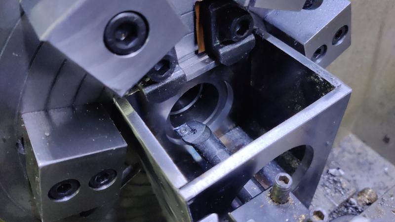
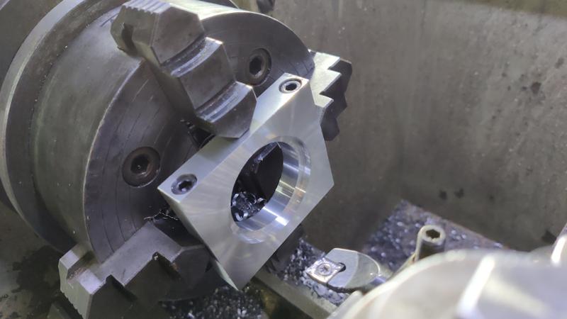
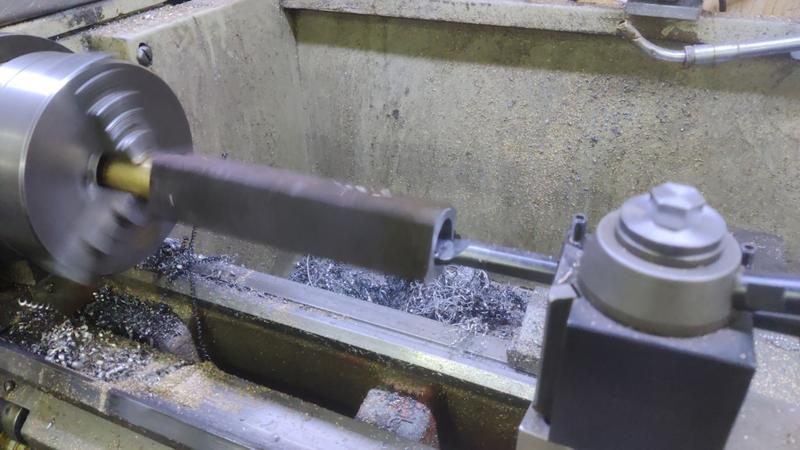
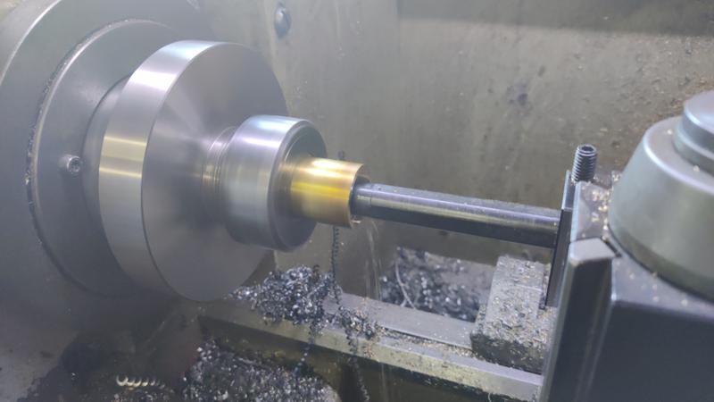
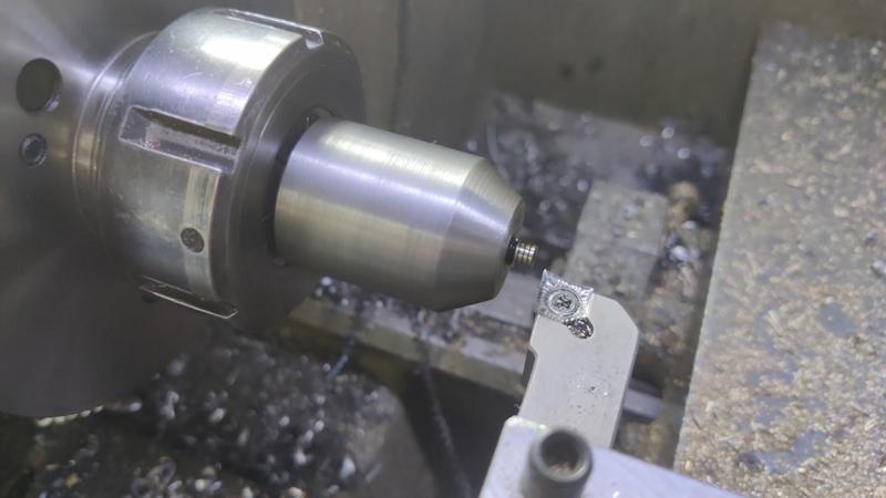
The first job of the morning was to fit one of the bearing retainers in the four-jaw chuck and clock it centred. It's not absolutely crucial that the bore is on the centre, but it may make assembly easier later if the centre of the hole is on the split line.

1701_clocking_bearing_retainer_800.jpg


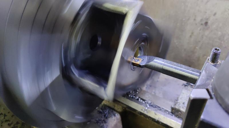
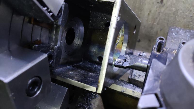
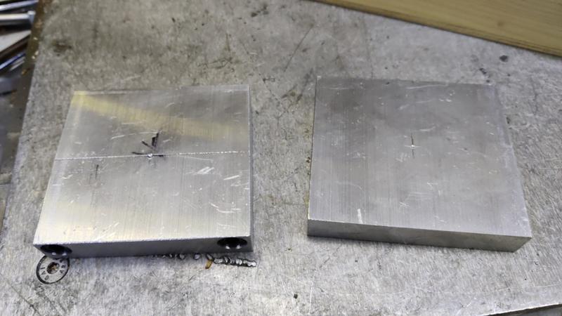
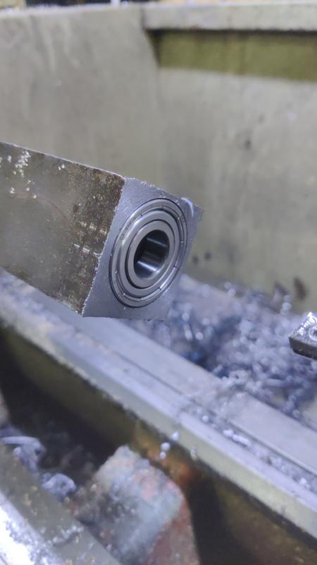
With that done, I skimmed the face (to make sure it ends up square with the axis of the bore) and then drilled and bored the through hole and the bearing seat:

1702_skimmed_drilled_and_bored_800.jpg


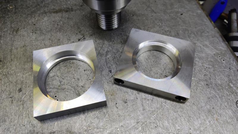
I did exactly the same on the other one:

1703_both_retainers_bored_800.jpg


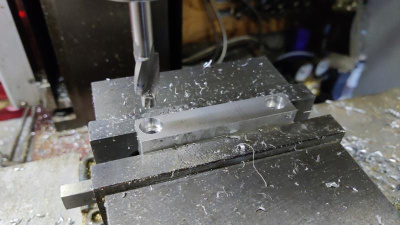
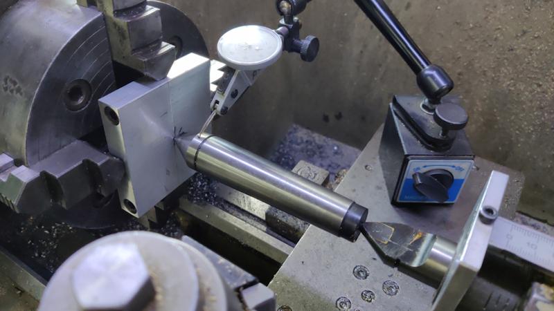
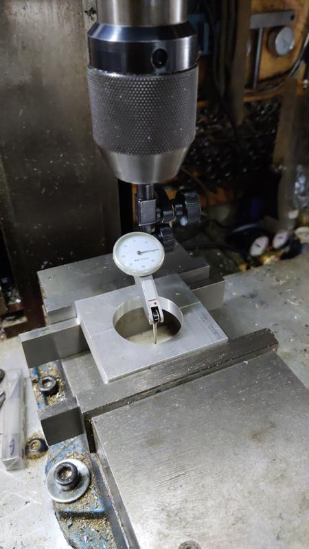
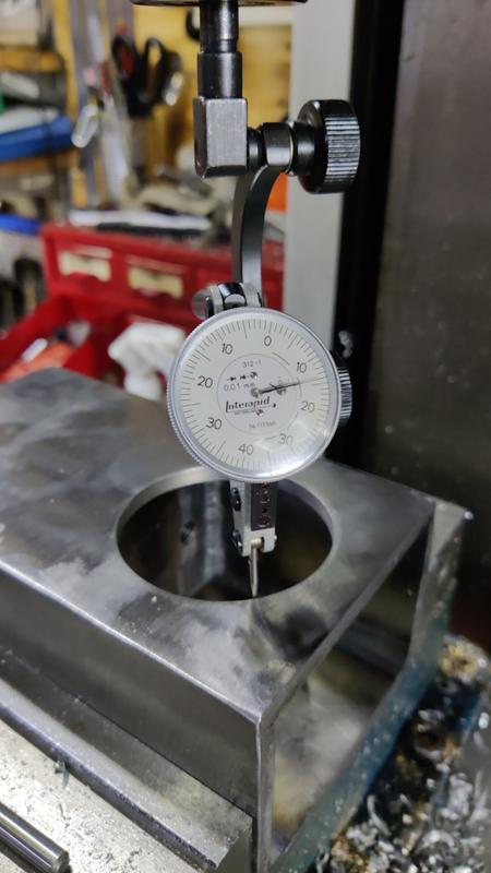
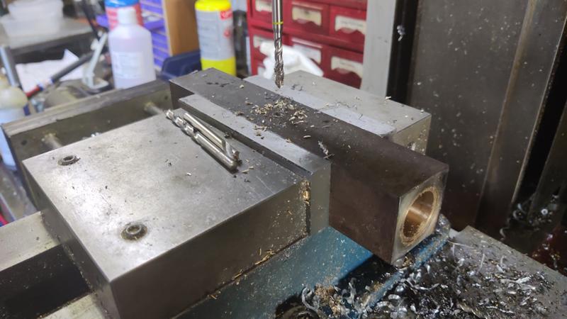
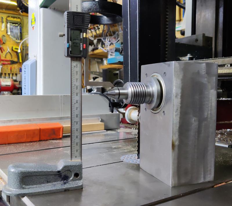
Each retainer was the mounted in the mill vice and the scales zeroed on the centre of the bore using a dial test indicator:

1704_clocking_bore_in_mill_800.jpg


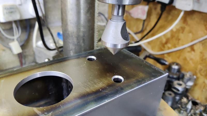
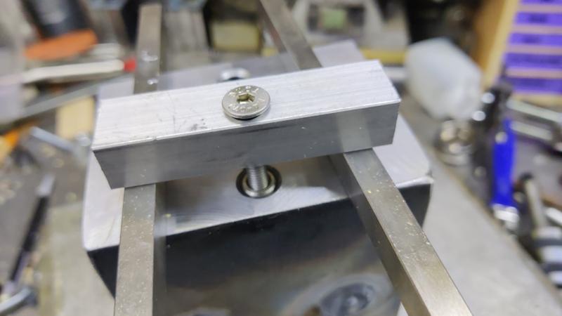
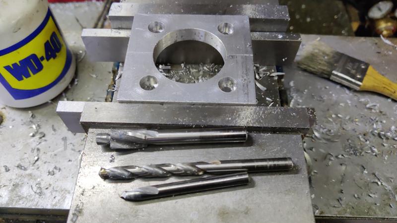
The mounting holes were then spot drilled, drilled and counterbored:

1705_drilled_and_counterbored_800.jpg


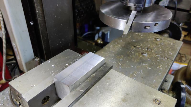
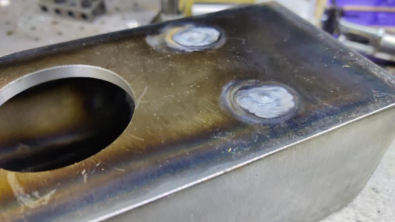
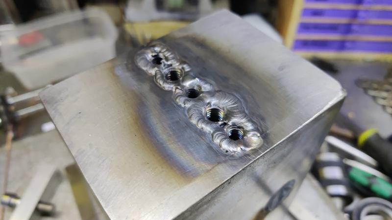
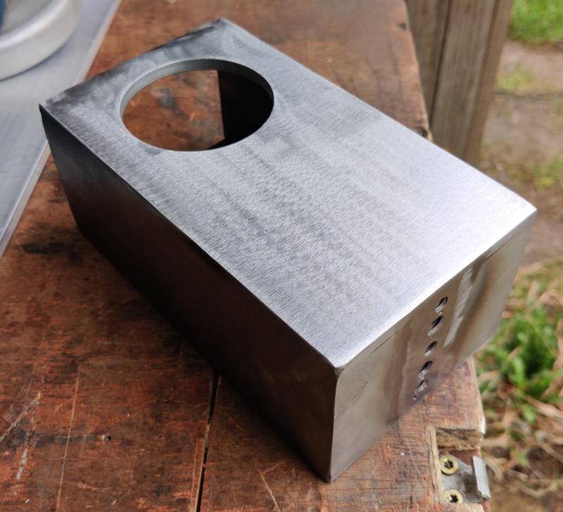
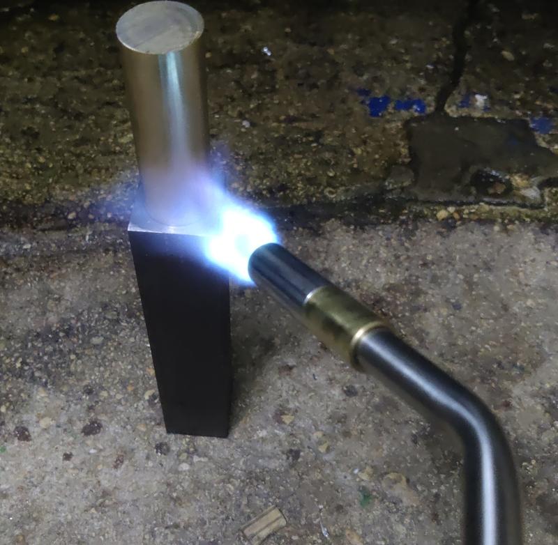
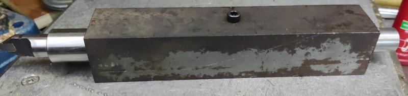
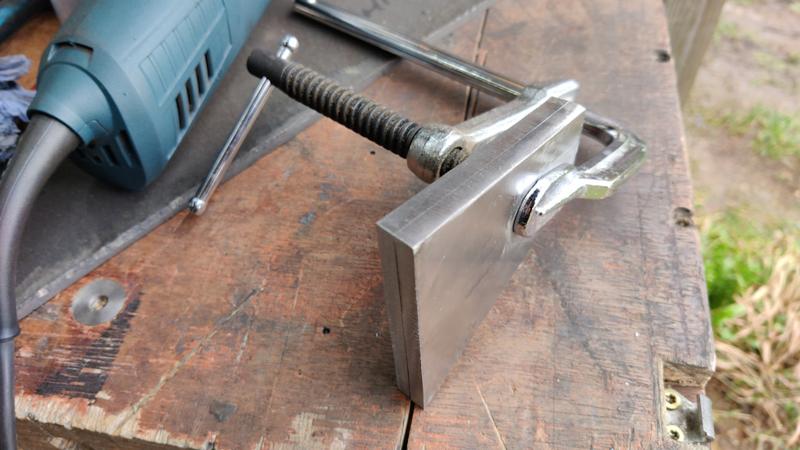
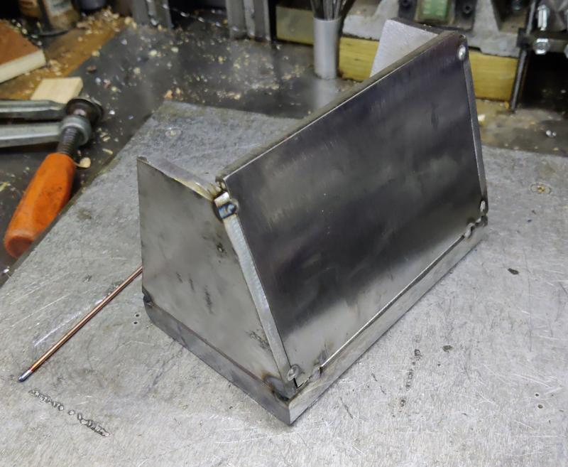
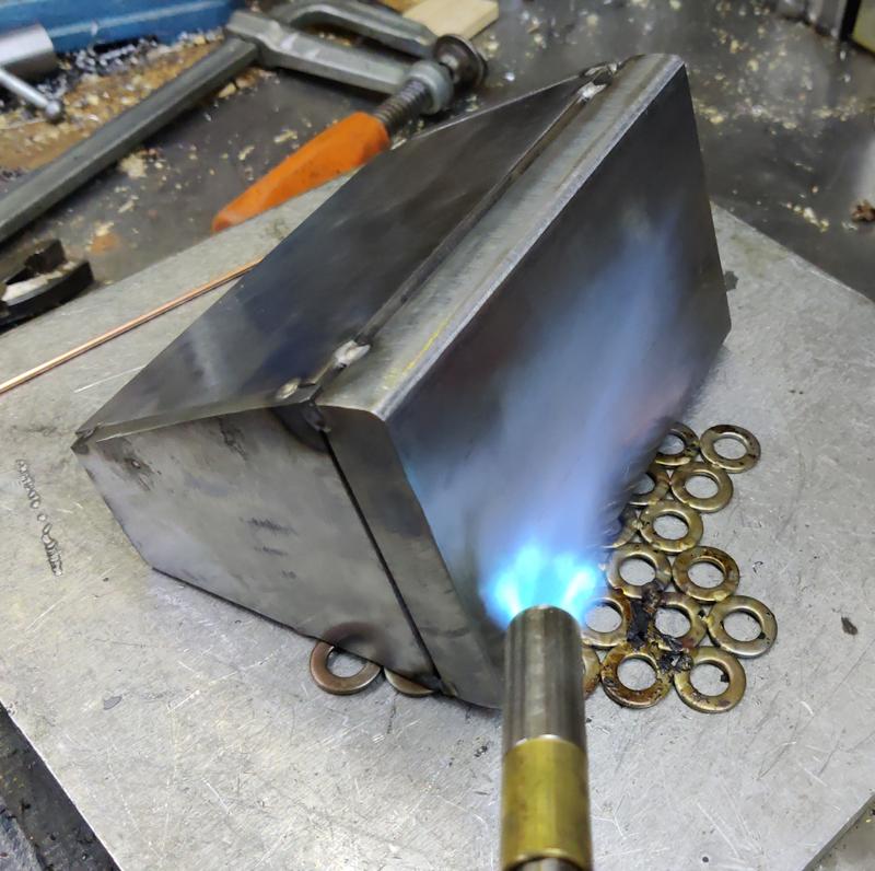
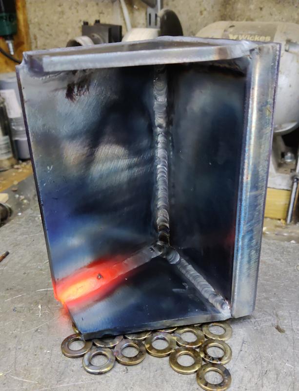
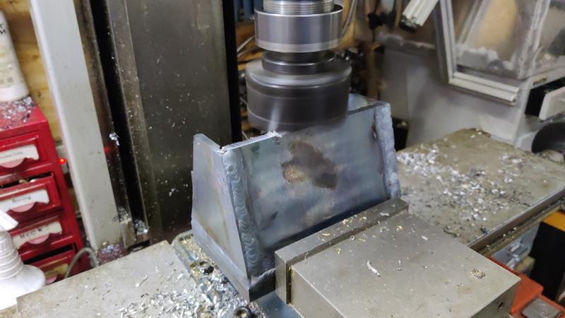
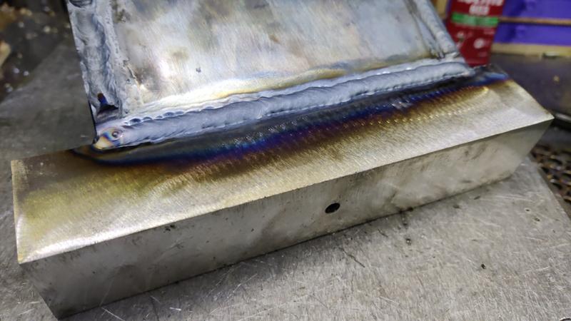
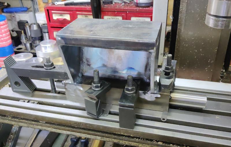
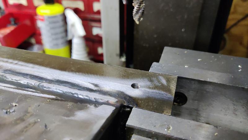
By this point, it was late enough that I felt I wouldn't upset anyone too much by making noise, so the angry grinder and flap disk were used to clean up yesterday's welds:

1706_flap_disked_800.jpg


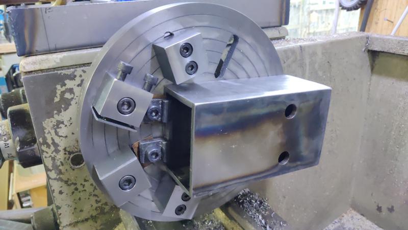
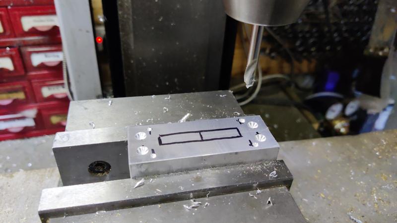
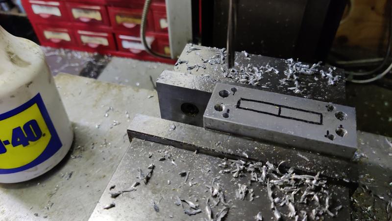
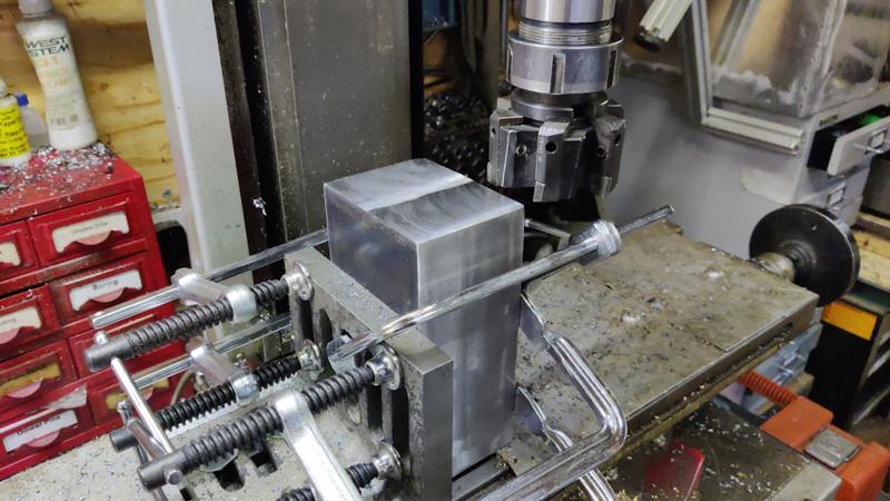
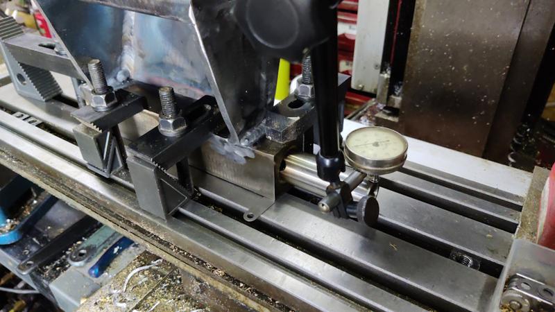
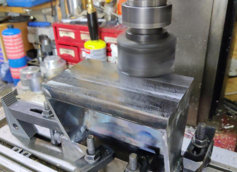
I could then mount the headstock in the mill vice and zero the scales on the centre of the bore as before:

1707_clocking_headstock_bore_800.jpg


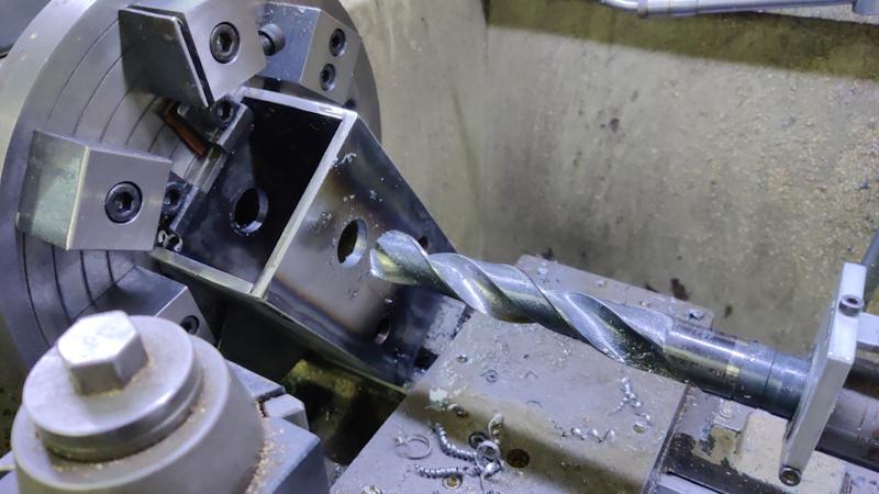
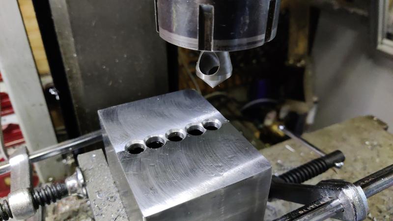
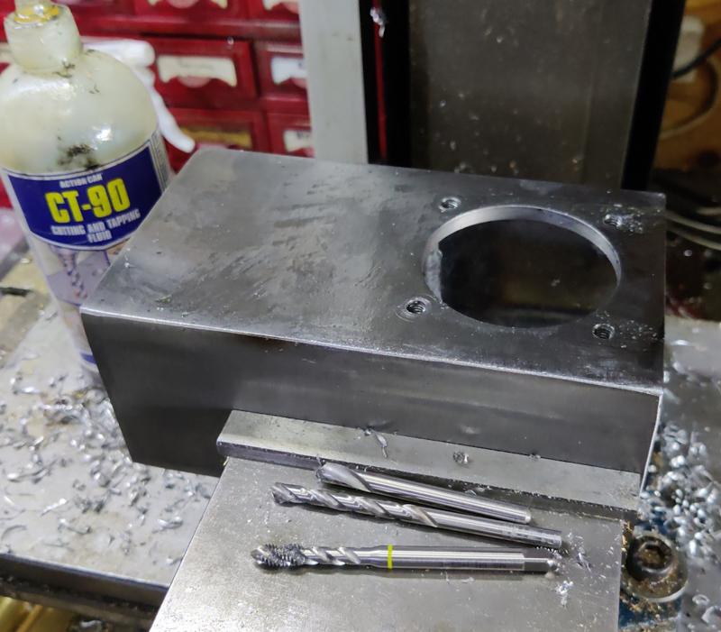
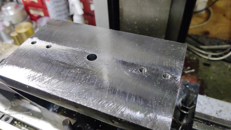
Holes to match the bearing retainers were spot drilled, drilled and tapped M6:

1708_headstock_tapped_800.jpg


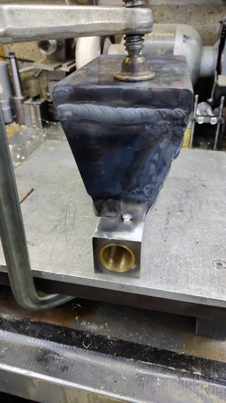
The final job on the headstock body was to add some small tapped holes to the top for a lid of some sort (to stop sawdust getting into the headstock). With the milling machine's head raised as far as it would go, there was just enough room to get a spot drill and a 2.5 mm drill bit in to drill these holes:

1709_drilling_high_up_800.jpg


If space had been a real issue, I could have mounted the headstock to an angle plate (or directly on the bed) as before, but this was a bit easier.

I didn't fancy machine tapping M3 and there wasn't room for a spring centre, so I took the headstock out of the mill vice and gingerly tapped the holes:

1710_hand_tapping_800.jpg


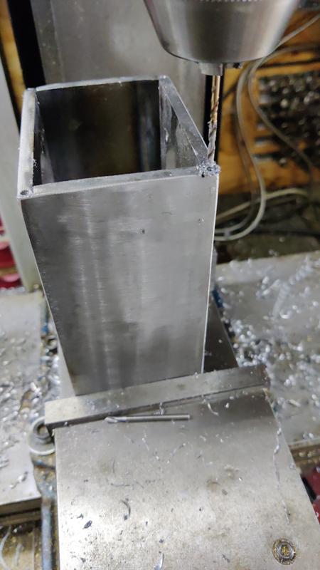
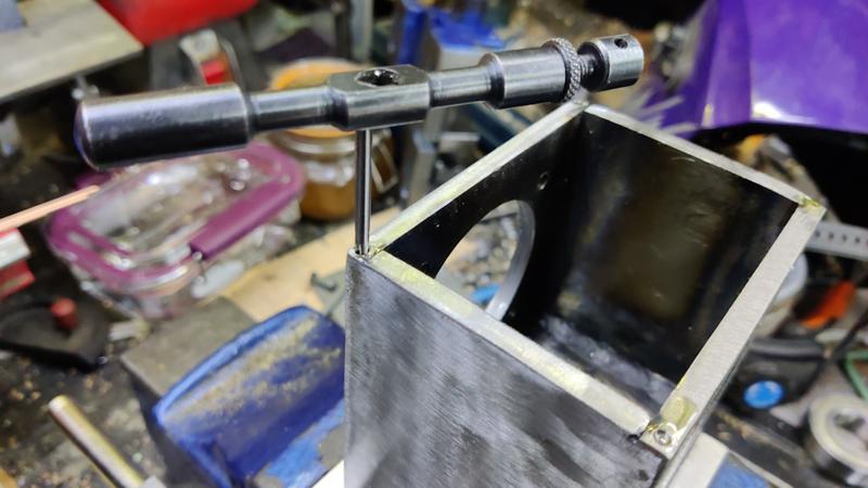
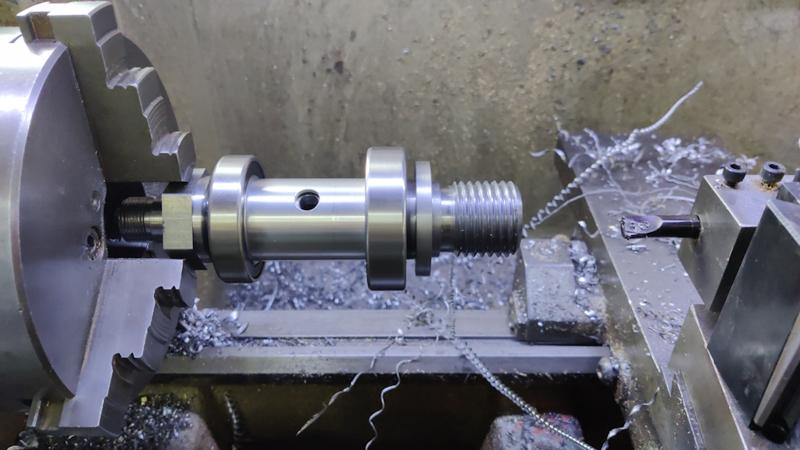
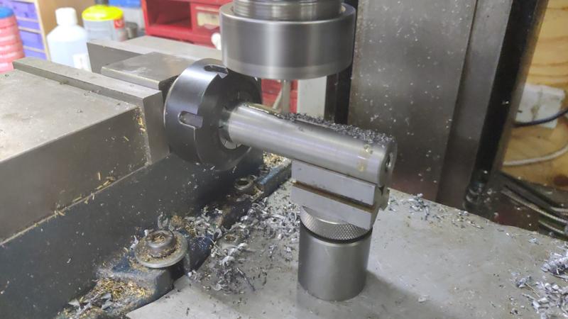
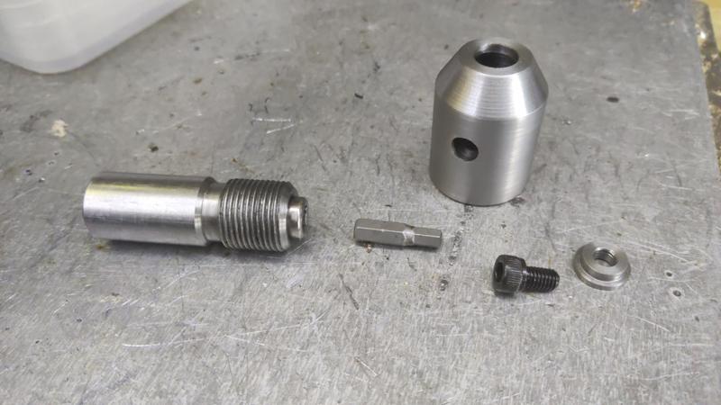
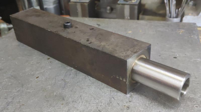
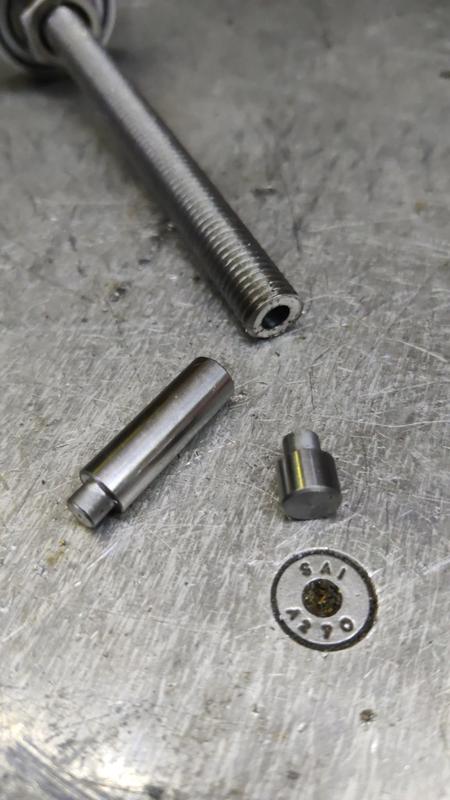
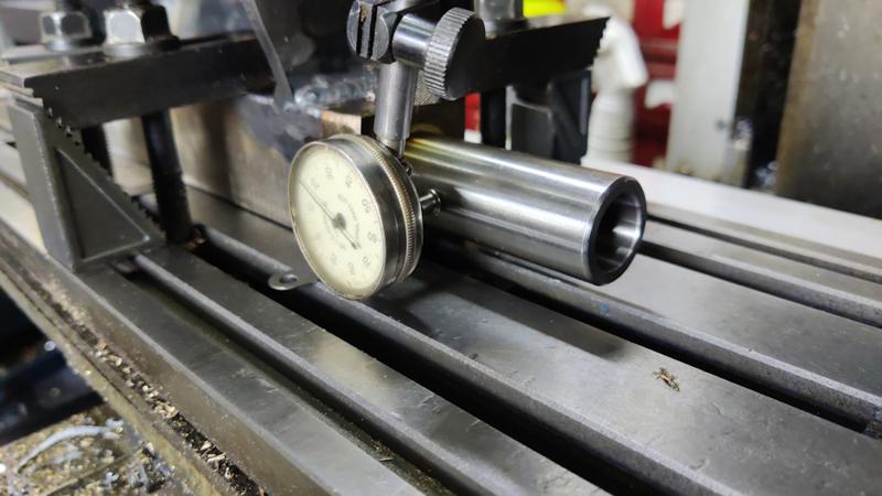
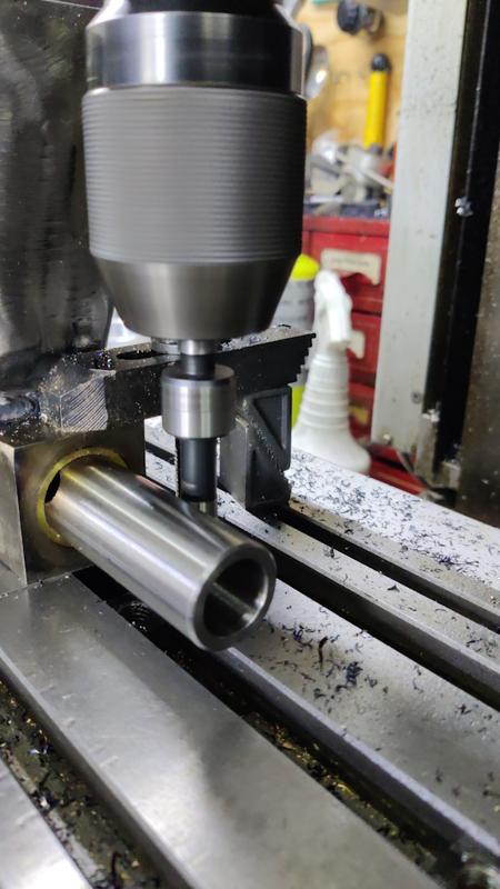
To add the hole for the tommy bar (for tightening a chuck or the rear nuts), I dismantled the spindle with a bearing puller and put the sleeve on a couple of small v-blocks in the mill vice. I could then drill a through hole 10 mm:

1711_drilling_for_tommy_bar_1_800.jpg


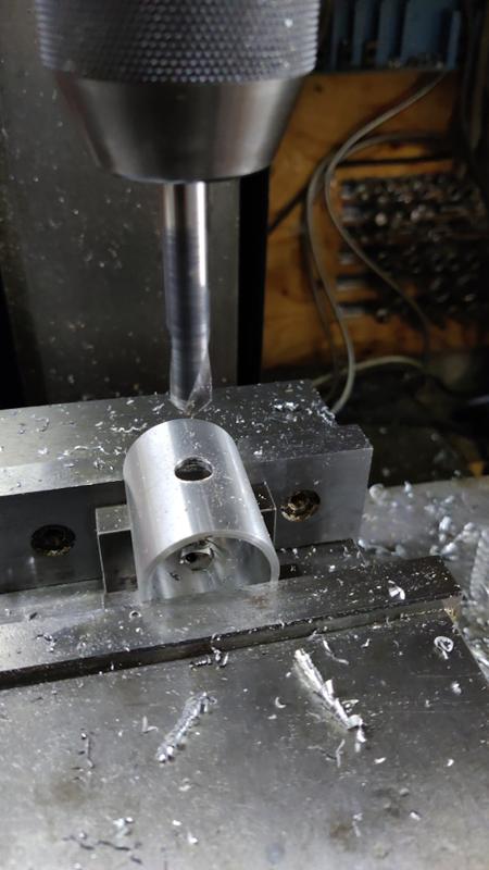
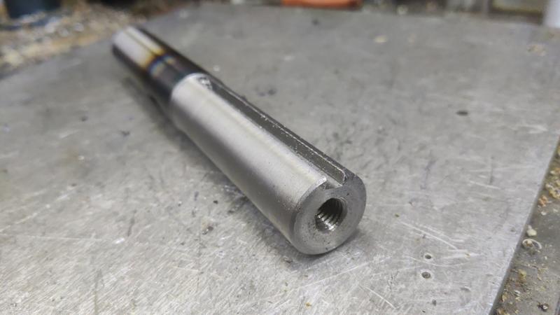
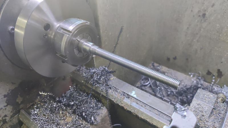
A collet block was used to hold the rest of the spindle for drilling the 8 mm hole for a tommy bar:

1712_drilling_for_tommy_bar_2_800.jpg


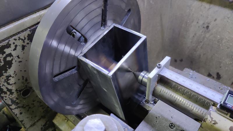
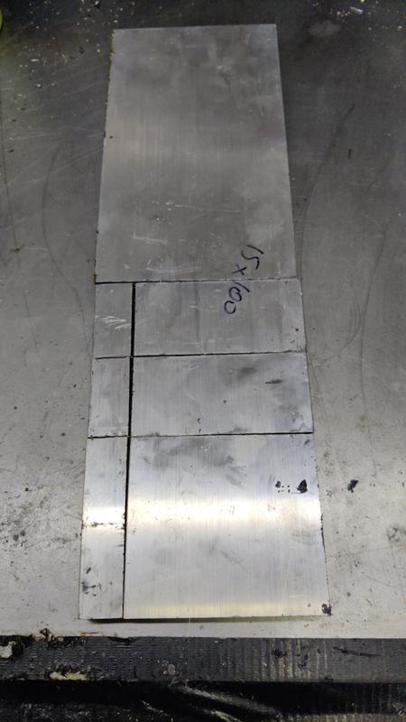
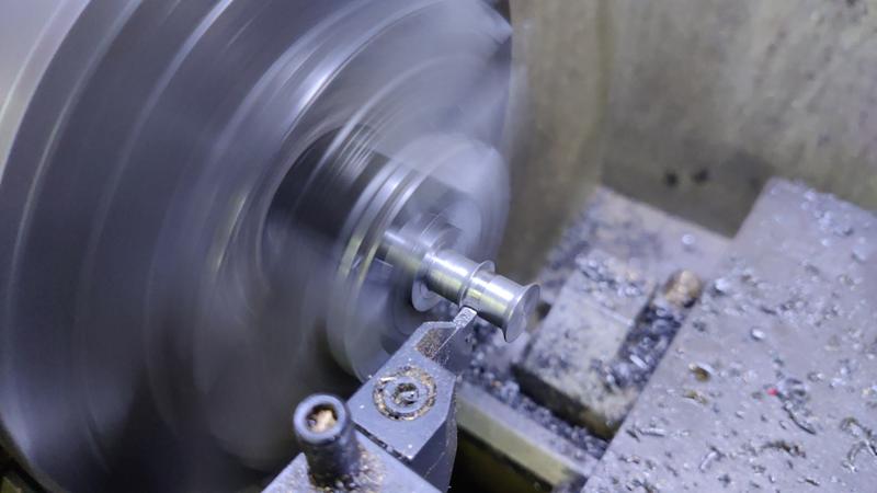
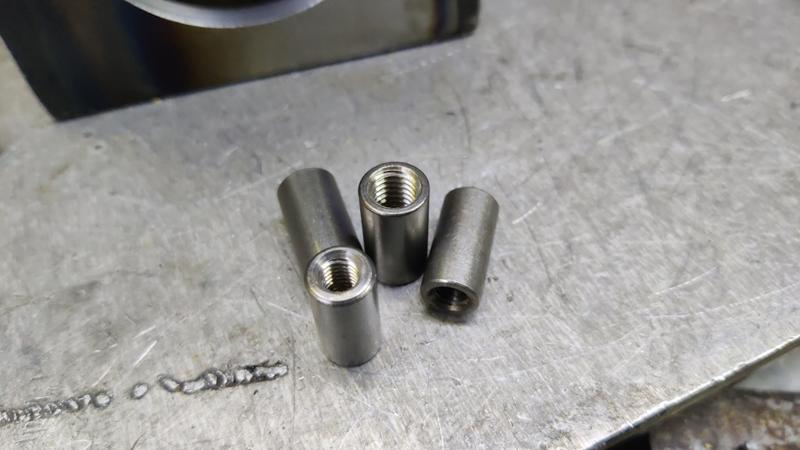
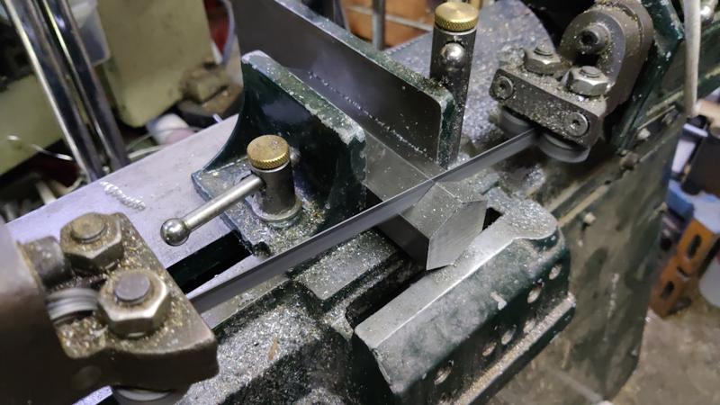
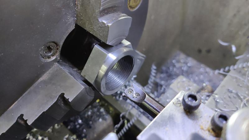
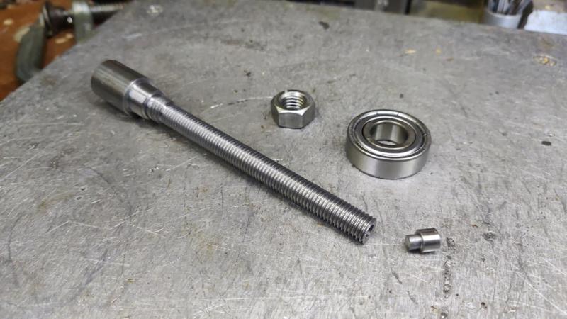
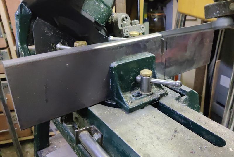
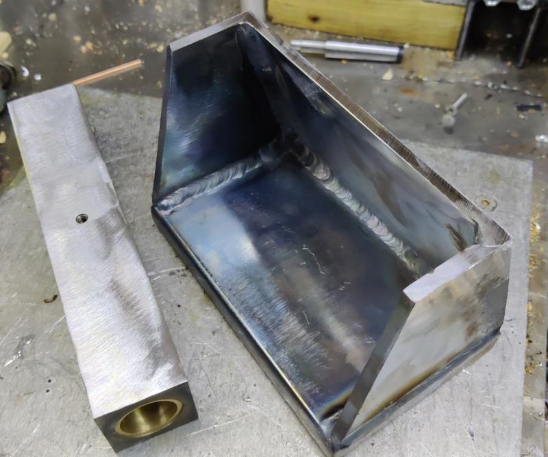
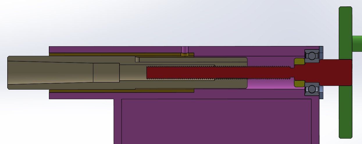
The next job was to get on with making nuts. I've got two to make, one with an M30×1.5 mm thread (for retaining the bearing) and one with an M20×1.5 mm thread for retaining the pulley. I've got a bit of big hex steel bar, so I used the horizontal bandsaw to chop off a couple of slices:

1713_sawing_nut_800.jpg


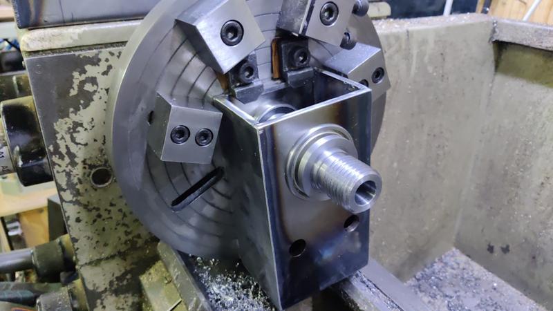
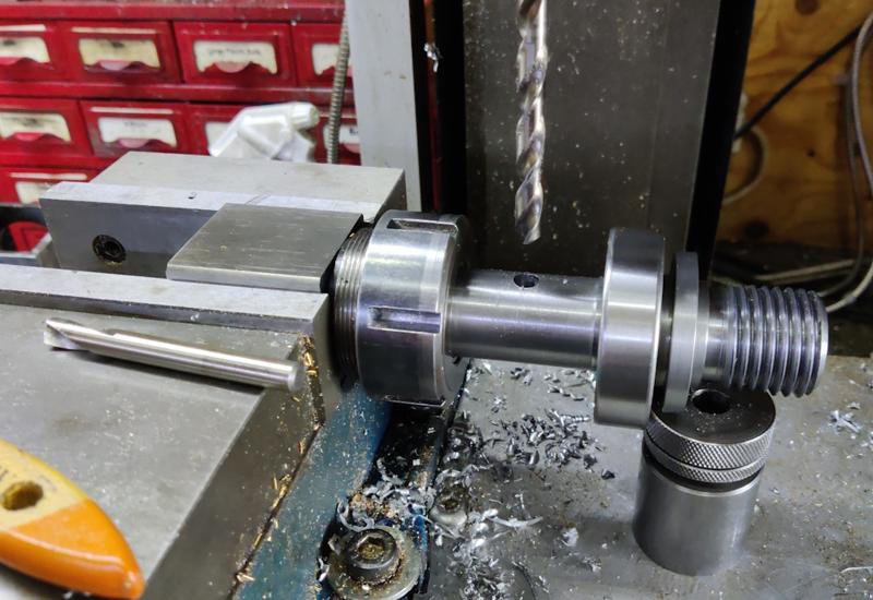
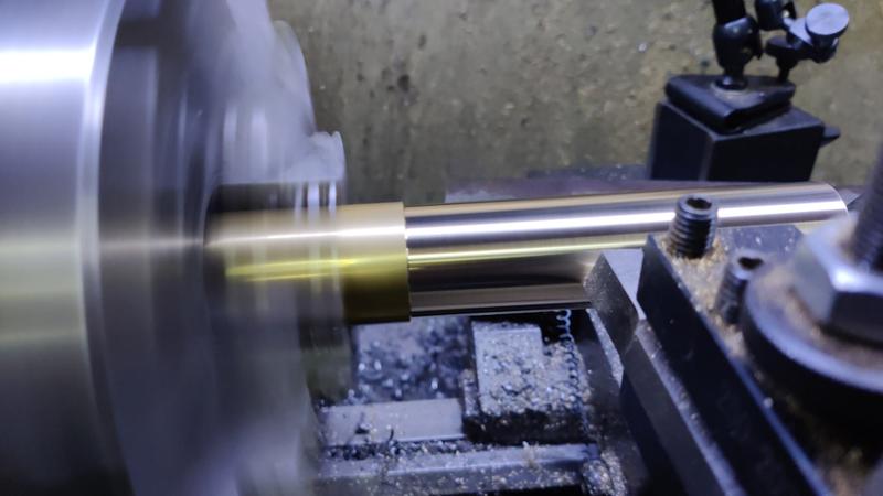
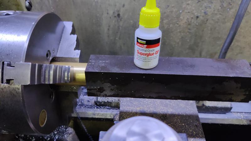
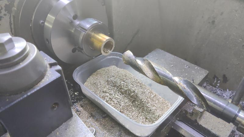
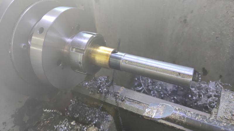
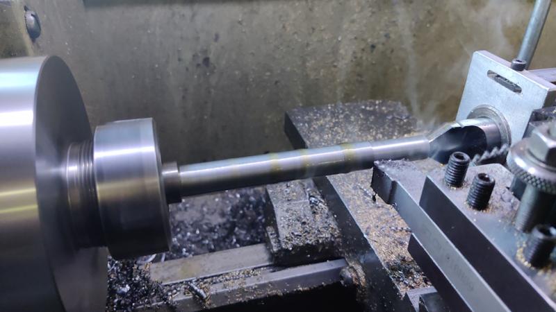
It could then be held in the three-jaw chuck and faced. It was then reversed in the chuck and faced again before turning a reduced diameter section (to push against the inner race of the bearing) and then drilling, boring and single-point threading:

1714_threading_nut_800.jpg


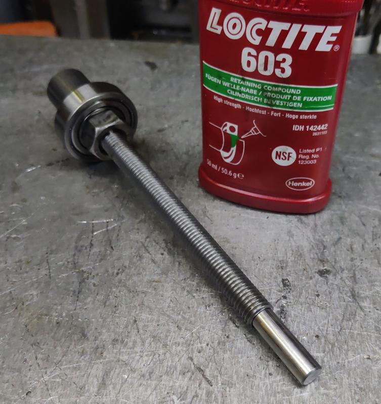
Before removing it from the lathe, the fit was tested with the spindle:

1715_checking_fit_800.jpg


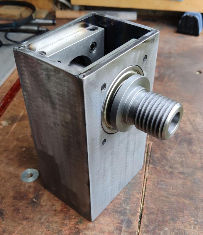
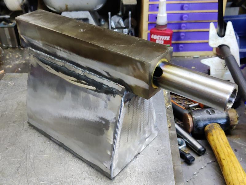
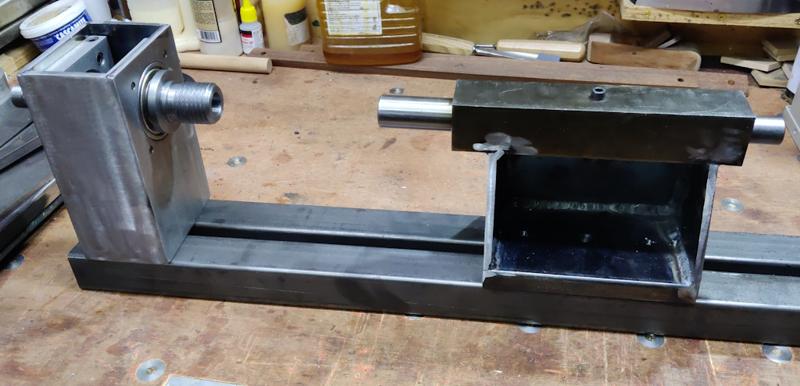
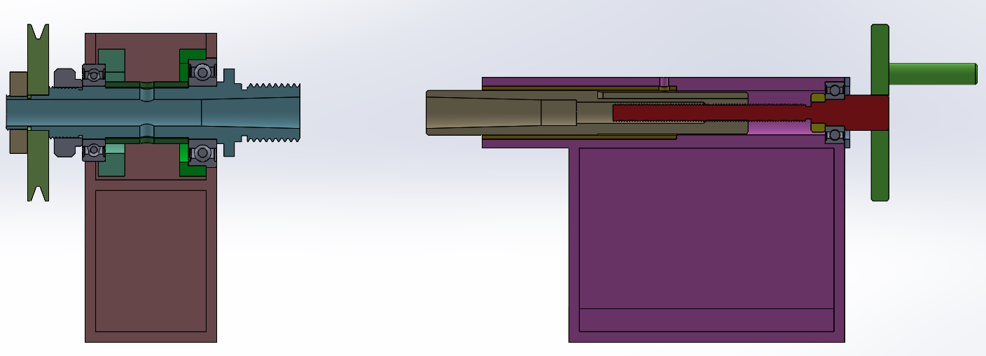
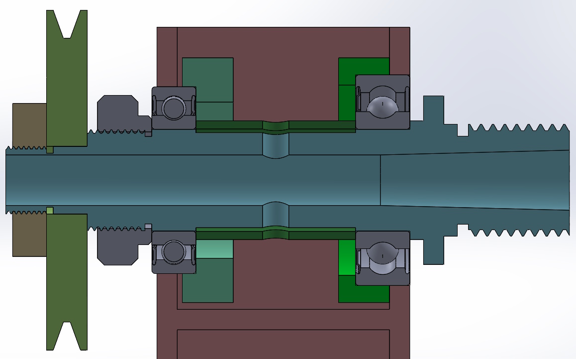
With that, everything on the headstock is essentially finished (apart from the lid, which is trivial, and the pulley, which needs a bit more thought yet). After assembling it the first time, I realised that my little ratcheting screwdriver bit holder thing has a lot more backlash than I thought and that made it quite hard to do up the lower screws on the bearing retainers while the spindle was in. In particular, it was going to make adjusting the bearing pre-load quite hard.

On a positive note, that method of assembly had ensured that the bearing retainers were perfectly aligned with the bores in the headstock. While everything was seated correctly (and the top screws were tightened down hard), I pulled the spindle out (leaving the rear bearing in the headstock). I could then tighten all the bearing retainer screws firmly against the headstock.

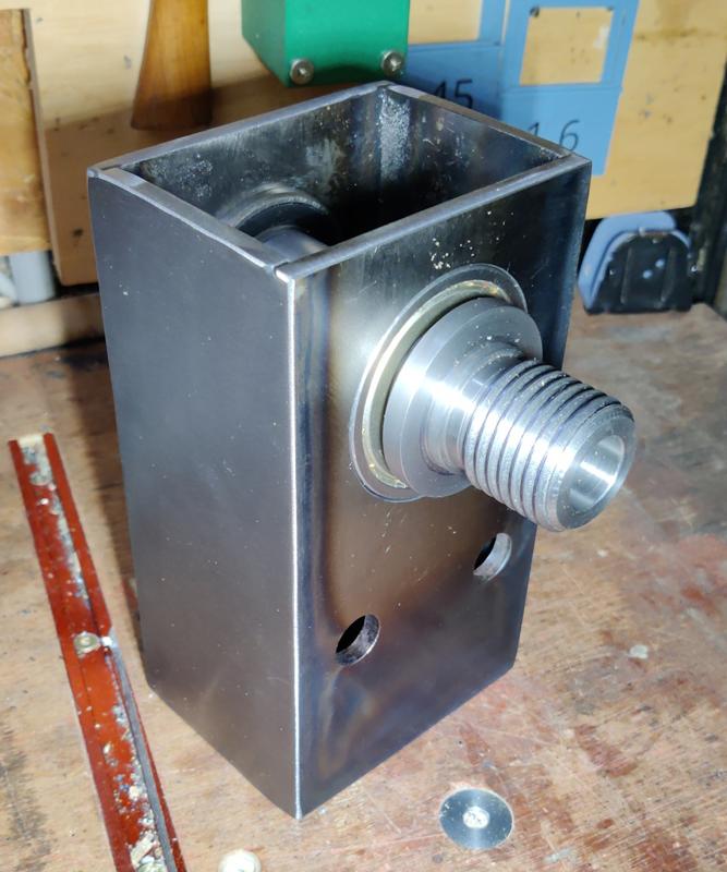
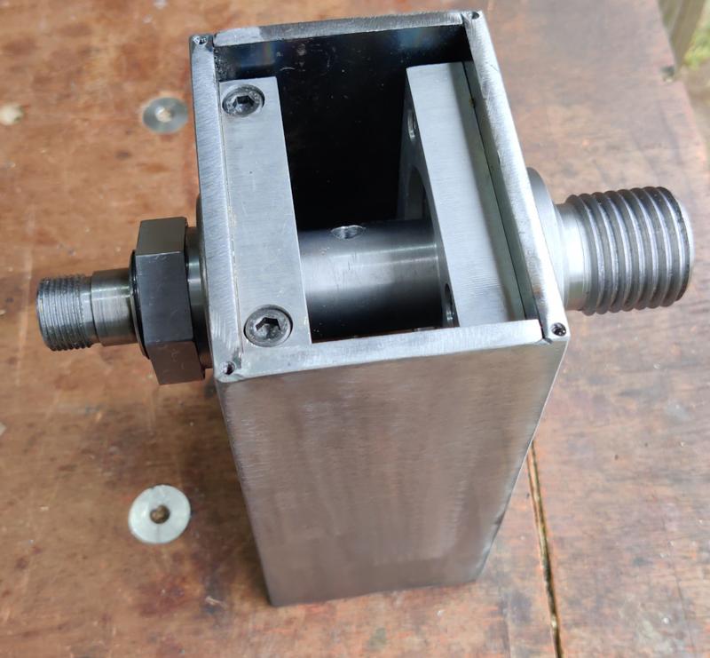
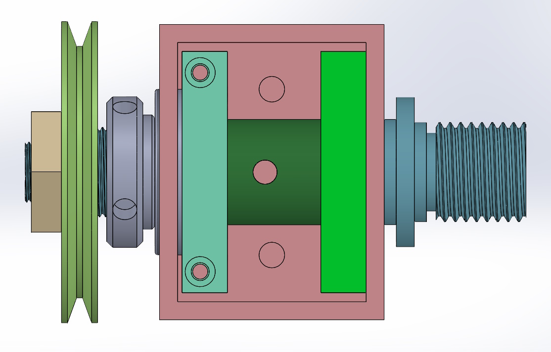
Having the bearing retainers held firmly against the headstock means that there's no way to use them to adjust the bearings. The simple solution to that was to remove the aluminium spacer before refitting the spindle. With that done, the nut that I made from hex bar sets the pre-load (depending on how far the bearing is pulled onto the shaft). I might make the nut a bit thinner and add a second one so I can lock them together and prevent movement, but for now it was good enough to call the headstock done:

1716_assembled_1_800.jpg


1717_assembled_2_800.jpg
 
After pondering for a while on what to do about the tailstock body, I grabbed a bit of 32 mm brass and skimmed it down to match the bore I'd turned last last weekend.

1718_turning_brass_800.jpg


It was turned to be a very close fit, so I could apply some superglue and push the tailstock onto the brass mandrel. It might seem a bit decadent to use brass as a turning mandrel, but (a) I've got loads of it and (b) if it works well, the mandrel will become part of the tailstock in due course, so I'm not actually wasting any brass by doing this.

1719_superglue_800.jpg


Once the superglue had cured, it was just a case of more drilling and boring...

1720_boring_800.jpg


... finishing with a fairly loose bearing seat for the tailstock handwheel bearing:

1721_bearing_fits_800.jpg


The final challenge for today was breaking the superglue joint. I started by applying lots and lots of heat:

1722_lots_of_heat_800.jpg


The problem with this is that brass has a higher thermal expansion coefficient that steel, so heating the assembly up probably causes it to bind more. If I were a patient man, I would have heated it up until I was sure that the superglue would have given up, then let it cool down and take it apart. The problem with that approach is that if the superglue hadn't given up, I'd have to try again. Instead, I heated it up until I was fairly sure the superglue would have given up, then I shoved a bit of bar stock down the hole and whacked it repeatedly with a club hammer until the brass bit came out.

The two pieces can now cool down overnight and then I'll think about what comes next.
 
After a bit of an overdue tidy-up, I decided to do a bit more work on the tailstock. I started by mounting the tailstock spindle in a collet chuck in the mill and milling a 5 mm wide slot along the EN3B.

1801_milling_antirotation_slot_800.jpg


I overshot the soft-ish EN3B bit a couple of times and went into the very hard Morse taper adaptor bit (the transition isn't obvious as I'd cut the end of the Morse taper adaptor slightly on the lathe with a carbide tool). Both times I broke the end mill I was using so this ended up being a three end mill job!

1802_slot_done_800.jpg


Once the slot was done, I took the brass piece that was used as a mandrel yesterday and bandsawed off the bit I want to turn into the the tailstock sleeve. I mounted it in a collet chuck with about the same amount hanging out each end of the collet and then went up through the drill bits, this time stopping at 22 mm:

1803_drilling_sleeve_800.jpg


I then used the boring bar, taking very light passes and also spring passes (not changing the setting, just doing another cut) to gradually increase the hole diameter...

1804_boring_sleeve_800.jpg


... until the tailstock spindle would slide smoothly through the bore:

1805_smooth_fit_800.jpg


The brass sleeve was then shoved back into the tailstock body and a hole spot drilled, drilled and tapped through both the steel and the brass:

1806_tapping_800.jpg


The anti-rotation screw needs to have a smooth end, so I dragged out a lantern chuck I made many years ago:

1807_lantern_chuck_800.jpg


With that held in the lathe, I could turn the last few millimetres of thread off to give a smooth end with a diameter slightly under the 5 mm of the milled slot:

1808_turning_screw_end_800.jpg


That's the bulk of the work for the tailstock body done: the spindle slides in and out smoothly, but won't rotate:

1809_tailstock_body_800.jpg


I still need to do something about retaining the handwheel bearing and I'll probably round off the top corners. I also need to make the base that will lift it up to the right height, but I'm pleased to have got this far. Next job will probably be to make the leadscrew that will pull/push the tailstock in and out.
 
Al, when you first aired this project, I thought of a nice old article from the Woodworker, back in the austerity years of the 1950s, showing how to make your own lathe. It was based around a salvaged bicycle frame and its bottom bracket. You probably needed a hacksaw and a file.

I might still dig it out, but only for peripheral interest - you're clearly not short of ideas on how to go about this!
 
To make the tailstock screw, I started with a length of 20 mm EN1A. I drilled a centre hole (which, if I'd have been thinking about it more, would have been smaller) and then pulled it further out from the chuck and, supported by a half-centre, roughed out the shape:

1810_rough_turning_screw_800.jpg


After getting all the dimensions to what I wanted them to be, I did both the threads with single-point tools: the M10 one because I don't have an M10 left-hand die and the M12 one because my M12 die wouldn't go over the M10 thread!

I then realised that the centre hole took away most of the strength of the end of the thread, so turning it down to 8 mm to push on the tailstock tool wasn't going to end well. After a quick ponder, I turned the end down shorter to get rid of most of the centre hole and then I drilled a 5 mm straight hole in the end:

1811_screw_cut_800.jpg


I could then make a little stub piece out of some 8 mm silver steel that will glue into that end hole and push on the tool:

1812_all_bits_provisional_800.jpg


After a quick test assembly, I discovered that the MT2 tooling doesn't protrude into the Morse taper adaptor anywhere near as I expected and hence my ejection tip wouldn't push the tool out:

1813_less_protrusion_than_expected_800.jpg


This is where a bit of serendipity came into play: as I'd made the tip as a separate piece, it was trivial to make a new, longer one:

1814_longer_extension_800.jpg


The tip got glued into the screw with Loctite 603...

1815_retaining_compound_800.jpg


... and then I could assemble it.

1816_assembled_800.jpg


The bearing isn't retained in the tailstock body in any way at the moment, but it was enough for me to give the ejection process a little try:

[youtubessl]ClY4MFS8hpI[/youtubessl]
 
Lons":1quvzh31 said:
You won't get many comments from me as there's nothing I can contribute but I am following your project with great interest. I suspect there are many like me and possibly loads of non member browsers who don't comment but find such threads incredibly interesting and useful.

:text-+1: Really interesting project, so far above my skill set it's atmospheric. Reminds me of working in an engineering shop when I was an apprentice, we were fitting facings/skirtings to the works new toilets and one of the engineers said to my old journeyman that as an engineer he had to work to tolerances of 1/1000th of an inch to which Robert replied "you're lucky we have to be bang on every time" :lol: :lol:
 
:text-+1: Have a little experience in engineering from uni, I loved using the metal lathes and milling machines but that was over 20 years ago! Very much enjoying watching this develop.
 
The next big job for the tailstock was to make the frame that connects the tailstock to the bed and ensures it stays parallel with the bed axis and at the right centre height.

I've decided to make the base of the bed out of some 20 mm thick hot rolled steel. This is a lot more substantial than it really needs to be, but it means I don't have to bother with weld nuts (the steel is thick enough to tap directly) and it gives me a lot of room for adjustment: I'll build the frame over size and then mill down the bottom of the base plate to get the centre height right. If I made it out of 6 mm steel and had to take 2 mm off to get the centre height right then the plate would be getting a bit thin.

I've got one piece of 20 mm × 100 mm hot rolled steel with some thick mill scale on it, so the first job was to clean off a lot of that mill scale (firstly with a non-woven preparation wheel and then with an 80 grit flap disc). I then cut a section off with the horizontal bandsaw:

2301_bandsaw_chop_off_800.jpg


To make the ends of the tailstock frame, I got a bit of 6 mm stock and cut it into bits using the angle grinder with a cut-off disc (it seemed a bit small to easily hold for use of the metal cutting circular saw):

2302_angle_grinder_cut_up_800.jpg


I then cleaned up the faces with a non-woven wheel and then clamped the two pieces together and used a flap disc to make them the same shape:

2303_clean_up_to_match_800.jpg


With that done, I tack-welded all the base bits together:

2304_tack_800.jpg


I then decided to pre-heat them a bit with a MAPP gas torch:

2305_pre_heat_800.jpg


I've no idea whether that was necessary or helpful, but I've never tried to TIG weld anything this thick before and I figured it couldn't hurt. If I had any sense, I probably would have stick welded it, but I enjoy TIG welding a lot more (and I'm a lot better at it).

Once I'd got bored of pre-heating, I turned the TIG welder up to the maximum current (210 A) and went for it:

2306_weld_800.jpg


By the end of the weld, it was quite hard to hold the TIG torch due to the heat coming off the tailstock base! I'll now leave it to cool down.

I said at the start of this project that I was going to try to do it without buying anything. Well, I've failed! I've got a couple of single phase motors that I could have chosen for the power source, but then an old 1.1 kW (1.5 hp) three phase motor popped up on ebay relatively locally. I was the only bidder, so I picked it up for the auction starting price £10. To run it, I need an inverter, but I found a 2.2 kW one brand new for £53, which wasn't too bad considering. Hopefully they'll both work! All being well, this should be much better than a single phase motor as I can more easily get variable speed operation.

2391_new_motor_800.jpg


It's a big old beast (and somewhat out of proportion to the lathe if I'm honest), but there should be plenty of power, even when running it at reduced speed.

2392_motor_plate_800.jpg


It's a 4-pole motor and hence only runs at 1420 rpm. Ideally I would have gone for a 2-pole one for the higher speeds that seems to be preferable for spindle work on a wood lathe (from what I've read). However, as it's such a powerful motor, I should be able to gear it up with careful choice of pulleys and that should bring the spindle speed up to where it needs to be. If I can figure out a way to modify the spindle to have a 19 mm (3/4") pulley mount, then I'll be able to swap pulleys between the motor and the spindle and pick between a 2:1 ratio and a 1:2 ratio with only two pulleys. The variable speed drive should sort out the rest, so that seems like the ideal thing to aim for. The only challenge will be sorting out the spindle's pulley-mounting thread, which is currently M20×1.5. If I could reduce it to M18×1.5, then I could just skim off the existing threads and start again. However, the through bore is 15 mm so that might be getting a bit thin. What I'll probably try to do is cut it as M19×1.5 and just do my best to align the new threads with the old ones. That's a challenge for another day though...
 
I reckon you will be quite safe running the motor at up to 120 Hz or so with the inverter and a minimum of say 20Hz for a standard inverter with V to F capability or down to 10hz or so if it has a sensorless vector mode.

For extended use at low frequency maybe add an instrument fan to the motor if the inverter cuts out due to motor overtemperature.

Good Luck
Bob
 
I'm impressed that you have bits of 20mm steel lying around as spare - no wonder you have chosen to make something quite substantial.

And it's encouraging to get Bob's ok on the power plant.
 
I'm often at speeds well below 1450 Al for sanding, drilling and if mounting largish lumps or out of balance wood so as long as you can achieve a decent speed range you won't have issues.
Only other question is what colour are you going to pain / powdercoat your masterpiece?

Wish I could weld like that btw.
 
9fingers":on9zldja said:
I reckon you will be quite safe running the motor at up to 120 Hz or so with the inverter and a minimum of say 20Hz for a standard inverter with V to F capability or down to 10hz or so if it has a sensorless vector mode.

I'll give it a go at the higher speed, although I'd be surprised if the voltage will get high enough for it to work well :eusa-think:

On a positive note, I rewired the motor (for delta rather than star) this afternoon and plugged it into the inverter and it's running well. I didn't go any higher than 65 Hz though.

Presumably the risk with running at a lower frequency is that it'll saturate and start getting rather hot?

I'd be quite surprised if this cheap inverter does anything sensorless to be honest (it was only a £50 inverter!) To be honest, I have an in-built dislike of sensorless motor control, but that's just because it was the subject of my PhD (albeit zero/low speed sensorless control of PM brushless motors, so not quite the same thing).

9fingers":on9zldja said:
For extended use at low frequency maybe add an instrument fan to the motor if the inverter cuts out due to motor overtemperature.

It looks like the motor has a fan inside the housing (which is fairly open so will need a bit of shielding to protect it from sawdust).

AndyT":on9zldja said:
I'm impressed that you have bits of 20mm steel lying around as spare - no wonder you have chosen to make something quite substantial.

There's a lot of project ideas I've had, and bought material for, that have never quite got to the starting line, let alone the finish line. This project will be using up a lot of that stock!

Lons":on9zldja said:
I'm often at speeds well below 1450 Al for sanding, drilling and if mounting largish lumps or out of balance wood so as long as you can achieve a decent speed range you won't have issues.

That's good to know, thanks Bob. I'll probably make a few different pulleys (I've got loads of round aluminium offcuts that came out of a skip a few years ago) and that'll give me quite a bit of freedom regarding drive ratio.

Lons":on9zldja said:
Only other question is what colour are you going to pain / powdercoat your masterpiece?

I'm not sure yet (it'll be paint, not powdercoat as powdercoating is a bit beyond my skill/kit level at the moment). On the principle that I'm trying not to spend any money, it'll probably be whatever I've got in the drawer (assuming it hasn't dried up). I absolutely detest painting (and I'm not at all good at it), so I'm dreading that phase of the project.

Lons":on9zldja said:
Wish I could weld like that btw.

Thanks! I don't consider myself a particularly good welder, but I do enjoy TIG and most of the evidence gets removed by the angle grinder anyway!
 
We've had visitors staying this weekend, so I haven't had a lot of workshop time. However, I managed to make some progress on the tailstock before they arrived and after they left.

The next job on the tailstock base was to clamp it in the mill vice and skim the top surface flat and level. I wasn't aiming for a particular height here, as long as it was higher than I would eventually want it to finish.

2501_milling_top_flat_800.jpg


With that done, the top pieces were ready to glue together:

2502_ready_to_glue_together_800.jpg


I clamped them firmly together, using some scribed centre lines to get the top of the tailstock roughly in line with the base and then tacked them in place:

2503_tacked_800.jpg


I could then weld around the more accessible areas of the join.

2504_welded_800.jpg


Once it had cooled down (and the visitors had left) I gave the welds a bit of attention with the angle grinder. It could probably do with a bit more, but it'll do for now:

2505_cleaned_up_a_bit_800.jpg


To work out the exact centre height of the spindle, I measured the largest diameter of a Morse taper 2 dead centre and shoved it in the spindle. I then used a height gauge to measure the height of the top of the dead centre (and subtracted half the diameter, giving a centre height of 128.6 mm):

2506_measuring_centre_height_800.jpg


I then needed to bring the tailstock centre to the same height. I clamped the tailstock upside down on the table and used a dial gauge, running along the spindle, to check for level. I added some feeler gauge stock underneath the tailstock, tweaking the size of the shims until it the spindle was level with the travel of the bed. In the end I had a 0.6 mm feeler gauge piece at the end and a 0.3 mm piece in the middle (the middle piece was there so that clamping the tailstock down in the middle wouldn't bend the tailstock).

2507_levelling_on_table_800.jpg


Once it was levelled on the table, I also aligned it with the X-axis of the table:

2508_aligning_to_table_800.jpg


All clamped up and ready to mill:

2509_clamped_for_milling_base_800.jpg


I used my big carbide face mill to mill the bottom of the tailstock. I had to take about 1.8 mm off the bottom to bring it down to the right height (which I measured by zeroing the height gauge on the top of the spindle, measuring the milled surface and then adding half the diameter of the spindle):

2510_milling_base_800.jpg


Once the base was milled, I used a edge finder to find the centre of the spindle in the Y axis...

2511_finding_centre_800.jpg


... and then drilled and tapped four M6 holes and drilled a central 10 mm hole. The 10 mm hole will be used for clamping the tailstock to the bed; the M6 holes will be used for some screwed-in pieces that will (hopefully) align it to the bed:

2512_drilled_and_tapped_800.jpg


The last job on the tailstock was to add another tapped hole, this time in the back:

2513_side_hole_800.jpg


That'll be used (if necessary) for a brass screw that will hold the tailstock in place if I need to prevent it from moving while the lathe is running.

With that done and a couple of bits of box section plonked haphazardly on the bench, it's starting to look a bit like a lathe:

2514_looking_like_a_lathe_800.jpg
 
Back
Top