• Hi all and welcome to TheWoodHaven2 brought into the 21st Century, kicking and screaming! We all have Alasdair to thank for the vast bulk of the heavy lifting to get us here, no more so than me because he's taken away a huge burden of responsibility from my shoulders and brought us to this new shiny home, with all your previous content (hopefully) still intact! Please peruse and feed back. There is still plenty to do, like changing the colour scheme, adding the banner graphic, tweaking the odd setting here and there so I have added a new thread in the 'Technical Issues, Bugs and Feature Requests' forum for you to add any issues you find, any missing settings or just anything you'd like to see added/removed from the feature set that Xenforo offers. We will get to everything over the coming weeks so please be patient, but add anything at all to the thread I mention above and we promise to get to them over the next few days/weeks/months. In the meantime, please enjoy!

Elevating stand for my new thicknesser

Yep. Great stuff.

As for the castors I think I understand. The force required to move it from under the bench will be far far greater than the force exerted by pushing a board through the planer.
 
Andyp":2vh0fv9e said:
Yep. Great stuff.

As for the castors I think I understand. The force required to move it from under the bench will be far far greater than the force exerted by pushing a board through the planer.


There is virtually no force involved in feeding a thicknesser apart from enough to lift the anti kickback pawls. From then on, the machine pulls the timber in and pushes it out the other side.
This machine is a single function thicknesser not a P/T.

Bob
 
IT WORKS!!!! :obscene-drinkingbuddies: It actually f***ing works! :obscene-drinkingbuddies:

When I have stopped being so pleased with myself (and find my tripod!) I'll try and shoot a video.

The controls are still all manual and some more titivating needed but the motor is more than strong enough.
After oiling the screw threads, current is below 10 amps at 12volts - about 60% of the rated motor current.

Now to think about a MosFet H bridge* to switch the motor and PWM system to slow it down as it approaches the correct operating level and fit some limit switches just in case!

Woodwork, metalwork and electronics all in one project - I'm having great fun and enjoying the mix of skills.

Bob

*I've already burned out a relay contact and using electronic switching will allow speed control too.
 
9fingers":3327bq6d said:
IT WORKS!!!! :obscene-drinkingbuddies: It actually f***ing works! :obscene-drinkingbuddies:

Why so surprised? Nobody here ever doubted it would.

9fingers":3327bq6d said:
Now to think about a MosFet H bridge* to switch the motor and PWM system ......

No idea what on earth that means but I am sure it wont take you long to sort.
 
Thanks for your confidence Andy but there was always the possibility that the motor might not be man enough for the job as I had no specification on it only a few crude measurements.
It was off a recycled golf caddy.

OK here comes some pics and videos.

This is the planer at its storage position. the lath across the top simply showing the top of the planer motor is below the height of the sides.


The pale surface at the top right of the picture is the level of my table saw and outfeed table. The planer needs to rise to level with this about 570mm.

This video is of the planer rising out of the cabinet. Not exactly exciting at 6mm per second or thereabouts
I've not found the tripod so please excuse the shakes (excitement?)


Here we are at the operating level - note the lath level between the two tables


And a better shot of the machine itself.


Current drawn fluctuates by an amp or so but this is what it was at the instant of the photo.


Another video clip of the downward run - possibly easier to judge the motion in this one.


Now to think about the limit switches whilst the components for the H bridge are on order.

Google H bridge might help Andy

Cheers

Bob
 
Thanks David!

Now chaps, please switch off your "can't learn won't learn" mode for a bit. This is not difficult

Here is the basic H bridge with a bit of a twist.


In the middle is the motor. It is simple 12v DC motor that reverses when you change the polarity of the power supply. A,B,C & D can be thought of as near perfect switches. Close switches A and B, and the motor drives the platform up, if instead you turn on C and D, the motor drives the platform down.

The name H bridge comes from the topology of the central part of the circuit.

Clearly B and C must never be on at the same time as the supply will be shorted out and the magic smoke will escape. The same applies for A and D.

In my application I want the platform to stop when it is exactly level with my outfeed table. To do this, I want slow the motor right down just before it gets to the correct level and then there will be minimal inertia/overrun when I switch off.

The pulse generator sends out big fat pulses most of the time when the up control is enabled which turns B on virtually 100% of the time so the motor runs at full speed. When the platform gets near to the top, the pulses are changed to narrow ones and the motor creeps up to the final position until the stop sensor turns it off and it should stop dead in its tracks.

I don't need any degree of accuracy on the way down so that is kept as a simple on/off full speed mode.

That is the theory and I hope to get the parts early next week and start playing.

Bob
 
Rod":1scu6rho said:
Video doesn't work on my phone using Tapatalk but still looks impressive.
That's a nice planer too.

Rod

I could never understand the attraction of tapatalk. Videos work fine on my iphone 3 using the safari browser.

I've been wanting one of those planers for years. There is nothing in UK like them (fixed table, moving head and induction motor) This one was imported from USA by the previous owner who only sold it as he had TWO!!

Bob
 
Well we've had this discussion before - it's so much easier navigating forums with Tapatalk and I can post photos etc direct.
I don't have trouble viewing other folks videos?
I looked at yours using safari where it directs you to Photobucket and there it works.

Rod
 
Rod":4r58b2zf said:
Well we've had this discussion before - it's so much easier navigating forums with Tapatalk and I can post photos etc direct.
I don't have trouble viewing other folks videos?
I looked at yours using safari where it directs you to Photobucket and there it works.

Rod

Hmm! I don't think there is anything strange about my videos - just mp4 files. Maybe Tapatalk and photobucket don't get on? or are the videos you have watched been from photobucket?

I did think about uploading to youtube but that seems slow and for these particular vids I don't think there would be a wide audience :lol:

Bob
 
I don't really know?
The last one I watched on here was DaveL's - no idea where it was sourced but I just clicked the arrow and it played?
There's been lots on UKW and again it's just click and play.

Rod
 
Bob
The stand looks great. Is the motor on the thicknesser still the US one? If so whats the finish like on the wood, I assume its running slower than intended?

Mark
 
That is brilliant Bob! Very impressive and thanks for the quick explanation on the H bridge. I had electronics in school so I understand a little, but out of all the practical sciences electronics is by far the closest to black magic! :lol:
 
Excellent Bob, well done. It's made me want to motorise the winding mechanism on my planer/ thicknesser.

As for all the electronics.............I'm sure we can find a village which still has a ducking stool. :lol:
 
the bear":rr5pkgij said:
Bob
The stand looks great. Is the motor on the thicknesser still the US one? If so whats the finish like on the wood, I assume its running slower than intended?

Mark

Hi Mark,

Yes it is the original motor and as you suggest is designed for 60Hz. It is single phase as well so no chance of changing the speed. I've not really used it much yet to assess the surface finish. I've still got my DW functional for current thicknessing jobs.
I will possibly change the motor for a 3 phase one, run it from an inverter (just because I can!) to get the shaft speed up to the design speed. There is no room for a larger motor pulley and I don't want to fit a smaller cutter pulley as the wrap angle on the belt drive would be less.

A further justification for the eventual motor change is that the voltage should be reduced in proportion to the frequency to stop it over heating. At the moment, it is rated for 230v 60 Hz so needs 192v at 50Hz. My mains is about 246v and I need to run it from a transformer to stop the overheating and of course that reduces the power output to 70% (varies with voltage squared) throwing away a horsepower nearly.

I can see from the state of the windings inside the motor, the previous owner has run it from normal mains and it has been cooking inside so I really need to do something.

Thanks for your interest

Bob
 
TrimTheKing":1p94j6ji said:
:text-bravo: :text-goodpost:

Love this thread, thanks Bob.

Cheers
Mark


Thanks Mark,

I sometime wonder if my mechanical stuff (and electrical/electronic) is a bit too far off beam for this forum but it certainly seems to interest a few members and hopefully gives an indication that stuff is possible with a bit of thought and a can do attitude.

Bob
 
9fingers":25ay6yws said:
TrimTheKing":25ay6yws said:
:text-bravo: :text-goodpost:

Love this thread, thanks Bob.

Cheers
Mark


Thanks Mark,

I sometime wonder if my mechanical stuff (and electrical/electronic) is a bit too far off beam for this forum but it certainly seems to interest a few members and hopefully gives an indication that stuff is possible with a bit of thought and a can do attitude.

Bob

Not off beam at all Bob. Fascinating. You diagram of the H bridge makes everything crystal clear. Still not sure if I will ever have the skills to replicate but your patience in explaining things is commendable.

Interestingly I cannot view the vids in Firefox, only Safari. Not sure which plugin is affecting things but for others who are struggling it might be worth trying a different browser.
 
Todays progress was adding limit switches. These will tell the controller that the platform is either at the bottom, storage position or at the top, the working position.
Eventually this will allow me to wheel out the machine, press the UP button and know that it will stop exactly at the correct level with the planer table at the same level as my table saw which serves as the planer outfeed table.
Similarly, when I have finished planing, I can press the down button and know it will stop at the bottom. This storage position is not critical so a more basic switch can be used with no fine adjustment.

This photo is the lower limit switch. It has a lever with a little roller on the end. This bears on a block of metal bolted on to the platform.


Note the bolt, head down, threaded into the block just beside the roller. This is used as the fine adjuster for the upper limit switch and has no relevance to the lower limit switch.

This photo is of the upper switch with a spring lever and should be more repeatable.


Here the platform is at the upper operating position and the end of the adjustment bolt is pressing on the spring lever. The thread on the screw has a pitch of 0.8mm so by small rotation of the screw and locking it with the nut and lock washer, I expect to be able to get a precise stopping position.


I mentioned earlier that I will reduce the speed of the motor when the platform nears the upper position.
This will be controlled by a magnetic window burglar alarm switch. I've ordered one from fleabay so there will be a short intermission whilst I wait for that to arrive.
Maybe tomorrow or Monday, the power mosfets will arrive and I can start playing with the H bridge.
I won't bore you with that detailed witchcraft other than declaring it working!

Bob
 
Nice one !

But it sounds like a load of chicks being run over by a lawnmower in the video lol

Sent from my ALE-L21 using Tapatalk
 
chippy1970":1m66eieh said:
Nice one !

But it sounds like a load of chicks being run over by a lawnmower in the video lol

Sent from my ALE-L21 using Tapatalk


That was one of the things that needs titivating. The chain needed a bit more tension and the jack legs lubricating. The main noise now is just the motor working fairly hard - the thing does weigh about 250kg!

Bob.

PS Interesting that you presumably used Tapatalk and viewed the videos OK whereas Rod said he could not see them.
 
Yeah just checked again on tapatalk you have to click the video then click follow the link

Sent from my ALE-L21 using Tapatalk
 
9fingers":etcukcor said:
Rod":etcukcor said:
Well we've had this discussion before - it's so much easier navigating forums with Tapatalk and I can post photos etc direct.
I don't have trouble viewing other folks videos?
I looked at yours using safari where it directs you to Photobucket and there it works.

Rod

Hmm! I don't think there is anything strange about my videos - just mp4 files. Maybe Tapatalk and photobucket don't get on? or are the videos you have watched been from photobucket?

I did think about uploading to youtube but that seems slow and for these particular vids I don't think there would be a wide audience :lol:

Bob

It's not just Tapatalk and Photobucket. All I get is a grey screen when I look at the link using Safari on the Mac. Tried switching off Extensions in case there was a conflict but it made no difference.
 
9fingers":1r4qlm2a said:
TrimTheKing":1r4qlm2a said:
:text-bravo: :text-goodpost:

Love this thread, thanks Bob.

Cheers
Mark


Thanks Mark,

I sometime wonder if my mechanical stuff (and electrical/electronic) is a bit too far off beam for this forum but it certainly seems to interest a few members and hopefully gives an indication that stuff is possible with a bit of thought and a can do attitude.

Bob

Definitely not, Bob. Always fascinating and inspirational.
 
9fingers":23z9p1ep said:
.....
I won't bore you with that detailed witchcraft other than declaring it working!

Bob

What do you use to construct the circuit, Bob? Wire-wrap? Veroboard (is that still around?)
 
RogerS":16mb3n4i said:
9fingers":16mb3n4i said:
.....
I won't bore you with that detailed witchcraft other than declaring it working!

Bob

What do you use to construct the circuit, Bob? Wire-wrap? Veroboard (is that still around?)

Yes Veroboard still exists and I use it quite a lot for low frequency projects. It is hopeless for high speed or RF projects when I use copper clad board with components on their backs legs in the air - dead beetle style.

This project needs consideration of the high currents up to 10/15 amps and so a mix of veroboard and solid copper wire busbars for the high current bits.

Bob
 
The postman did not bring me any goodies yesterday to build the H bridge so I have continued the job with parts I already had.

I promised you no witchcraft - this simply switches and relays.

This circuit is designed to take signals from the up, down and stop press buttons in combination with the upper and lower limit switches and produce un ambiguous up and down signals and be as 100% fail safe as possible.
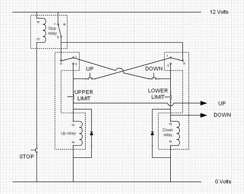


Under no circumstances must the up and down signals be on at the same time . If you follow the red path below, this is what happens when the UP push button is pressed momentarily (provided the upper limit switch is still closed).
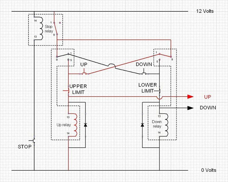


The uprelay coil is energised, the UP output signal changes from 0v to 12v and vitally, the supply to the Down button is removed and so there is no way the once UP has been selected can a Down command be issued.
The up relay continues to be energised until either the up limit switch opens or the stop button is pressed**

From the symmetry of the circuit, you can see that if the Down button was pressed first, the Up button would be disabled too.

**The only reason that there is a stop relay used in the design is because I did not have any matching normally closed press buttons but I do have lots of relays so I used on the convert a NO switch into a NC one.

The circuit is also designed so that any failure of the switches, relays or damage to the limit switch wiring will result in no operation rather that engage an operating mode that could cause damage.

Just before you ask about the diodes across the Up and Down relay coils, when a coil is switched off, the collapsing magnetic field generates a negative voltage pulse that could damage the drive inputs to the H Bridge, these diode will safely conduct away the voltage spikes by shorting them out. This is known as back EMF.

So if you want to make sure that only one of two events can occur at one time but either can come first, this is sort of circuit to do the job. It also has uses for a panel game situation when you need to know who pressed first and to lockout out all subsequent presses.

Here endeth todays lesson :lol:

Bob
 
9fingers":bp68d83z said:
..........I promised you no witchcraft - this simply switches and relays...........

Relays are witchcraft. Tie him to a stake, quick, and someone fetch the matches........

;) :lol:
 
What happens when you press both UP and DOWN at the same time? By my reckoning, you have volts on both up and down feeds to the motor. But I could be wrong.
 
Mike G":llsnb9di said:
9fingers":llsnb9di said:
..........I promised you no witchcraft - this simply switches and relays...........

Relays are witchcraft. Tie him to a stake, quick, and someone fetch the matches........

;) :lol:


Well the circuit is quite similar to a No Volt Release switch which virtually all of us will have in our workshops and so we all cast spells regularly then!

Bob
 
RogerS":2hg9psmb said:
What happens when you press both UP and DOWN at the same time? By my reckoning, you have volts on both up and down feeds to the motor. But I could be wrong.

Either one or the other should happen first and disable the other or an erroneous state will not the tatched

There could be a very short duration pulse equal to the operating delay of the relay - between application of the current to the coil and the contacts opening. Not likely to happen but it could in theory.

Bob
 
Seeing that you have up and down relays, could you not save the cost of 3 MOSFETS by using the relays to reverse the motor and just one MOSFET to modulate the drive power ? Would also eliminate the "both on" risk since relay changeover contacts are inherently free from that possible default condition.
 
chataigner":1ijtsw98 said:
Seeing that you have up and down relays, could you not save the cost of 3 MOSFETS by using the relays to reverse the motor and just one MOSFET to modulate the drive power ? Would also eliminate the "both on" risk since relay changeover contacts are inherently free from that possible default condition.


A valid question David. The relays that I have more than "a rest of lifetime stock" of are not man enough for DC inductive loading. They quote 7.5 amp resistive maximum.
The motor max running current is 15 amps and heaven knows what the inrush starting current is. I would not want to risk welding the contact closed - I already did that once when experimenting and it was a panic to kill the mains supply before something nasty happened.

Many automotive relays are good with high current inductive DC but the snag is that they are specified as "replacement for Ford XXX" etc rather than their performance spec.

Power mosfets are dirt cheap now. Mine were less than a pound each delivered. I've used mosfets at this sort of power level for a bass guitar amp for my son years ago but not for switching so it will also be a learning experience for me.

The mosfets arrived today together with some other items that I was a bit low on. 8 mosfets and 50 transistors for £11 ish. The suppliers have duplicated the order and so far seem only to have charged my CC once! I'd already bought a spare set, now I have 3 spare sets. So maybe I'll be using mosfets in some other projects soon!

Progress might be a little slow as I have to drop off Mrs in town and then walk to a diabetic eye scan. This involves pupil dilation drops - hence no driving and it will be a while before my vision returns to accept bright lighting for detailed electronics assembly.

Bob
 
Well I shall jump over the "witchcraft" and just show the completed H bridge and the speed controller electronics.
Here is a photo of the resultant spells.


All the controls have been fitted into another box.
UP, DOWN and STOP push buttons, an on off switch and a power indicator LED. The open hole is for a mains fuse holder which I had to order and still has not arrived ( I thought I had some in stock....)


The control box is fixed to the rear wall of the stand. in this way I don't need any safety interlock to stop the controls being operated when the planer is under the bench. This happens naturally as I can't reach the buttons until the stand is rolled out from under the bench and neither can I roll it away until it's lowered.
Uses the KISS principle :lol:

I could not find a box that would both fit and house the buttons as well as the relays so the latter are in a box by themselves.


Everything is mounted on the back of the stand out of the way.

With the boxes open


and all covered up ready to go


Pleased to say that despite everything being tidied up, it still works!

There is a little bit more design and metalwork to do to tidy up and protect the upper ends of the jack screws but that is about it.

Bob
 
Back
Top