It never ceases to amaze me the skills and generosity of the member of this forum.
I spent a couple of fascinating hours with Dr Al yesterday in his Tardis of a workshop. I am so grateful to him for his time and and skills to create the necessary parts for the Binding Channel Routing Jig I'm building.
First, the off the shelf stuff.

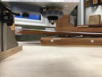
Ignore for the time being the cutter and plastic doobrie at the bottom. The 4040 extrusion, it's mounting brackets, the gantry plate, the V wheels are all available to but from suppliers of cnc and 3D printer kits and parts. These comprise the travel rail on which the router carriage will be mounted.

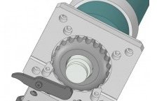
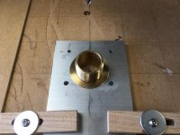
The router carriage plate is a piece unequal aluminium angle which needs some shapes cut out of it to accept, would you believe a 1" BSPP flange nut and the hole through with the router cutter would protrude. So I had to program my CNC machine to mill the first hole.
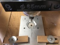
Then I milled the hex of the nut which I had reduced in thickness by filing.
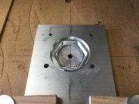
This was followed by the shape of the flange, including a small chamfer around the hex to accommodate the casting.
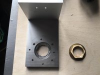
And lets see if it fits.
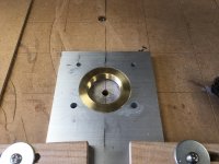
Yay!
Some of you will have spotted that some photos show four screw holes while others show eight. well, that would be down to me making a rubbish job of locating the screw holes for the router base.
At this point is where I sought the skills and expertise of Dr Al. He not only has the resources of a 3D printer, but also a milling machine and the brain to calculate the coordinates for the milling machine to drill, countersink and deburr 4 new holes which exactly match the screw holes of the router base.
We took no photos at Dr Al's because there was a bit of time constraint, but I'll show results here.
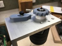
The 1" BSPP flange nut comes suppled with a 30mm nipple, which for the uninitiated like me is an external threaded piece of brass tubing which screws into the the nut.
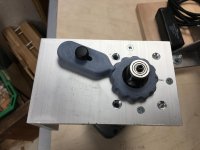
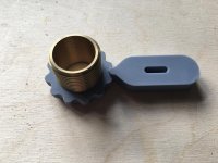
This forms part of the micro adjust facility of the jig. The other part is a plastic ring fitted to the nipple so that the combination can be screwed in and out of the carriage plate, thus adjusting how much router cutter is revealed.
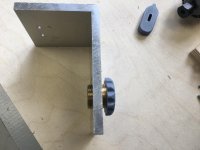
While we were in the Tardis, the 3D printer produced the plastic ring, the indents of which allow a catch to engage, so that it locks the ring in place after adjustment.
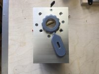
The only problem with this arrangement is that the combination of the router chuck and cutter length was insufficient to protrude enough for the desired rebate sizes. In addition, commercial chuck extensions made the cutter protrude too far. I have a new one one for sale if anyone is interested.


So, Dr Al manufactured one there and then!

And when I've bought an 8mm collet for my router, I will post more images of the completed jig.
Dr Al, a huge thank you for your time, skills and machinery, without which I could not have got this far.