• Hi all and welcome to TheWoodHaven2 brought into the 21st Century, kicking and screaming! We all have Alasdair to thank for the vast bulk of the heavy lifting to get us here, no more so than me because he's taken away a huge burden of responsibility from my shoulders and brought us to this new shiny home, with all your previous content (hopefully) still intact! Please peruse and feed back. There is still plenty to do, like changing the colour scheme, adding the banner graphic, tweaking the odd setting here and there so I have added a new thread in the 'Technical Issues, Bugs and Feature Requests' forum for you to add any issues you find, any missing settings or just anything you'd like to see added/removed from the feature set that Xenforo offers. We will get to everything over the coming weeks so please be patient, but add anything at all to the thread I mention above and we promise to get to them over the next few days/weeks/months. In the meantime, please enjoy!

Micro Adjust stuff on a jig I'm building

Malc2098

Sequoia
Joined
Jul 3, 2016
Messages
8,311
Reaction score
1,313
Location
Tiverton
Name
Malcolm
A shout out to UK members who 3D print.

I'm in the process of building a router binding channel jig for accurate, clean binding and purfling rebates on my instruments.

I've seen a commercial micro adjust version and would like to replicate it.

It comprises a 'donut' about 50 -60mm diameter with an approximately 30mm hole, thickness about 10mm. Inside this hole is a thread.

The second part is the male of that thread, with about a 26mm hole in that.

Dimensions are approximate at the moment.

Before I commission anyone and make up drawings, is the concept of those two threads on a 3D printer doable?

Thanks in anticipation.
 
Malc2098":qtwnmxh0 said:
A shout out to UK members who 3D print.

I'm in the process of building a router binding channel jig for accurate, clean binding and purfling rebates on my instruments.

I've seen a commercial micro adjust version and would like to replicate it.

It comprises a 'donut' about 50 -60mm diameter with an approximately 30mm hole, thickness about 10mm. Inside this hole is a thread.

The second part is the male of that thread, with about a 26mm hole in that.

Dimensions are approximate at the moment.

Before I commission anyone and make up drawings, is the concept of those two threads on a 3D printer doable?

Thanks in anticipation.

Sounds doable from a quick scan of what you've written.

The components all sound quite big so good wall thickness which can help. If you want very fine pitch for micro adjust, you might be better with a heatset insert and a steel thread, but again I think I'd need some sketches to have a better idea. If there's any force going through the thread then bear in mind that threaded 3D printed things are much better under compression (pushing the layers together) than tension.

I'm away at the mo, but happy to convert some pencil sketches into CAD for you when I'm back home.
 
Dr.Al":30bbepw4 said:
Malc2098":30bbepw4 said:
A shout out to UK members who 3D print.

I'm in the process of building a router binding channel jig for accurate, clean binding and purfling rebates on my instruments.

I've seen a commercial micro adjust version and would like to replicate it.

It comprises a 'donut' about 50 -60mm diameter with an approximately 30mm hole, thickness about 10mm. Inside this hole is a thread.

The second part is the male of that thread, with about a 26mm hole in that.

Dimensions are approximate at the moment.

Before I commission anyone and make up drawings, is the concept of those two threads on a 3D printer doable?

Thanks in anticipation.

Sounds doable from a quick scan of what you've written.

The components all sound quite big so good wall thickness which can help. If you want very fine pitch for micro adjust, you might be better with a heatset insert and a steel thread, but again I think I'd need some sketches to have a better idea. If there's any force going through the thread then bear in mind that threaded 3D printed things are much better under compression (pushing the layers together) than tension.

I'm away at the mo, but happy to convert some pencil sketches into CAD for you when I'm back home.


Thanks, Al. No rush. I won't be binding/purfling for some months yet.

The donut will be under compression. The weight of the router will be on top and the edge of the instrument body underneath.
 
I've 3D printed a number of pieces with screw threads. That's pretty easy to do. I think Dr Al's suggestion of using metal threaded inserts makes good sense. Or embdded hex nuts could be done. I've also had good luck with them.
 
Dave R":3i11rg2x said:
I've 3D printed a number of pieces with screw threads. That's pretty easy to do. I think Dr Al's suggestion of using metal threaded inserts makes good sense. Or embdded hex nuts could be done. I've also had good luck with them.


Thanks, Dave. It's not got a lot of work to do; just raise or lower, by micro amounts, the guide bush that sits on the instrument. What I've got to be mindful of is not creating anything too thick, so the router cutter doesn't reach through. The plate I have for the router carriage is 10mm aluminium L section.
 
If you need it I can create a file for 3D printing with the threads you need but I still think a threaded insert would make sense.
 
Dave R":7crffl2b said:
If you need it I can create a file for 3D printing with the threads you need but I still think a threaded insert would make sense.

Thanks, Dave. I'm minded to wait for Dr Al to return. But in the meantime, are there inserts that would accommodate an approximate 25mm hole in them?

F852C05C-6960-497D-8760-652CCE75EFA4_4_5005_c.jpeg

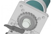
I was thinking of a plastic ring fixed on top of the carriage plate with a female thread, and the micro adjust ring under the carriage with the male thread. Both allowing a 23mm cutter through their apertures.

Dimensions are still approximate.
 
Malc2098":36txzu4r said:
Dave R":36txzu4r said:
If you need it I can create a file for 3D printing with the threads you need but I still think a threaded insert would make sense.

Thanks, Dave. I'm minded to wait for Dr Al to return.

I'm back - but I got back late yesterday so haven't looked at it yet.

Malc2098":36txzu4r said:
But in the meantime, are there inserts that would accommodate an approximate 25mm hole in them?

Probably not to be honest (although something could be custom made without too much difficulty). You could obviously move something up and down with (e.g.) three machine screws spread evenly around, but the screws would have to be turned the same amount to avoid any pitch.

Malc2098":36txzu4r said:


I was thinking of a plastic ring fixed on top of the carriage plate with a female thread, and the micro adjust ring under the carriage with the male thread. Both allowing a 23mm cutter through their apertures.

Dimensions are still approximate.

What is that CAD model image from? If that's a CAD model of your jig, PM me a STEP file or similar and I'll see what I can suggest. If not, then perhaps a few pencil sketches?
 
Dr.Al":1vcpopn0 said:
Malc2098":1vcpopn0 said:
Dave R":1vcpopn0 said:
If you need it I can create a file for 3D printing with the threads you need but I still think a threaded insert would make sense.

Thanks, Dave. I'm minded to wait for Dr Al to return.

I'm back - but I got back late yesterday so haven't looked at it yet.

Malc2098":1vcpopn0 said:
But in the meantime, are there inserts that would accommodate an approximate 25mm hole in them?

Probably not to be honest (although something could be custom made without too much difficulty). You could obviously move something up and down with (e.g.) three machine screws spread evenly around, but the screws would have to be turned the same amount to avoid any pitch.

Malc2098":1vcpopn0 said:


I was thinking of a plastic ring fixed on top of the carriage plate with a female thread, and the micro adjust ring under the carriage with the male thread. Both allowing a 23mm cutter through their apertures.

Dimensions are still approximate.

What is that CAD model image from? If that's a CAD model of your jig, PM me a STEP file or similar and I'll see what I can suggest. If not, then perhaps a few pencil sketches?


Pencil drawing under construction for PM.
 
Dave R":2mh3upnc said:
I guess I'll stand down and leave it in Al's hands. I'm not sure of threaded insrts that large but I expect you could find a large nut that would work. I didn't realize you were talking that large. My 3D printer could easily handle making a knob with internal threads that large and it would be a simple thing to model up in SketchUp for that.

I don't think it's the diameter of the thread that's the issue, it's the pitch. An M30 coarse pitch (M30×3.5) thread would be quite easy to print in a 3D printer as it has a 3.5 mm pitch and hence there's lots of material in the "triangle" of the thread. Now try to print an M30×0.25 thread and it gets a bit more challenging. Given that this is a micro-adjust jig, I assume a fine-pitch is desirable.

I think 3D printers can be "persuaded" to go down to about 0.5 mm pitch at a push, but the thread will be weak and the part might not last very long. If the thread is under tension, then it'll be even worse (even with a coarse pitch).

I'll do a quick CAD model from Malc's pencil sketches when I get home and once I've definitely got my head around what he's trying to achieve, it'll probably be clearer whether a 3D printed part is viable. My gut feel is the best option will be for Malc to buy a chunk of brass and I'll stick it in the lathe and cut the threads, but I'm getting a bit ahead of myself having not fully understood the requirements yet :D
 
It never ceases to amaze me the skills and generosity of the member of this forum.

I spent a couple of fascinating hours with Dr Al yesterday in his Tardis of a workshop. I am so grateful to him for his time and and skills to create the necessary parts for the Binding Channel Routing Jig I'm building.


First, the off the shelf stuff.

8AD461B8-50AA-4F15-B81E-4905AFF19E9A_1_201_a.jpeg

Ignore for the time being the cutter and plastic doobrie at the bottom. The 4040 extrusion, it's mounting brackets, the gantry plate, the V wheels are all available to but from suppliers of cnc and 3D printer kits and parts. These comprise the travel rail on which the router carriage will be mounted.

02283BFA-CEF4-4470-A1AD-28AC0A376250.jpeg

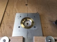
The router carriage plate is a piece unequal aluminium angle which needs some shapes cut out of it to accept, would you believe a 1" BSPP flange nut and the hole through with the router cutter would protrude. So I had to program my CNC machine to mill the first hole.
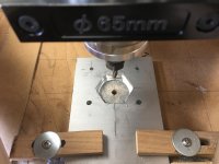
4F63C67A-F745-4855-A42A-0A1E6AAC6200.jpeg

Then I milled the hex of the nut which I had reduced in thickness by filing.
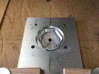
1F3BEC22-720F-4001-B064-980740672164.jpeg

This was followed by the shape of the flange, including a small chamfer around the hex to accommodate the casting.
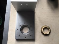
2F96BA6D-0D32-42F2-B90E-52EC42666B4C_1_201_a.jpeg

And lets see if it fits.

BCFED909-D875-4C5D-A023-93B0BDA16756.jpeg

Yay!

Some of you will have spotted that some photos show four screw holes while others show eight. well, that would be down to me making a rubbish job of locating the screw holes for the router base.

At this point is where I sought the skills and expertise of Dr Al. He not only has the resources of a 3D printer, but also a milling machine and the brain to calculate the coordinates for the milling machine to drill, countersink and deburr 4 new holes which exactly match the screw holes of the router base.

We took no photos at Dr Al's because there was a bit of time constraint, but I'll show results here.

The 1" BSPP flange nut comes suppled with a 30mm nipple, which for the uninitiated like me is an external threaded piece of brass tubing which screws into the the nut.
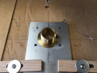
5EA83AAC-A016-469F-AB77-14B3149C16A2.jpeg

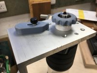
This forms part of the micro adjust facility of the jig. The other part is a plastic ring fitted to the nipple so that the combination can be screwed in and out of the carriage plate, thus adjusting how much router cutter is revealed.
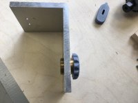
ED5C5BD2-8F24-49A4-AF31-84277F860AE1_1_201_a.jpeg

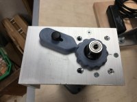
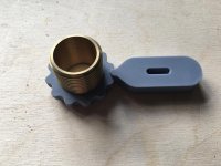
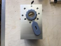
While we were in the Tardis, the 3D printer produced the plastic ring, the indents of which allow a catch to engage, so that it locks the ring in place after adjustment.
C4011255-0B27-4B6B-840E-F309496363B5_1_201_a.jpeg

069FD04E-6573-4528-A3F5-1C346DFB4714_1_201_a.jpeg

The only problem with this arrangement is that the combination of the router chuck and cutter length was insufficient to protrude enough for the desired rebate sizes. In addition, commercial chuck extensions made the cutter protrude too far. I have a new one one for sale if anyone is interested. :oops:

EE311792-F7F5-41B7-AF17-5DD1355519B1_1_201_a.jpeg

So, Dr Al manufactured one there and then!

BA3A4767-6FEE-47F6-8BD2-3D8D5DB9527A_1_201_a.jpeg

And when I've bought an 8mm collet for my router, I will post more images of the completed jig.


Dr Al, a huge thank you for your time, skills and machinery, without which I could not have got this far.
 
Brilliant and a prime example of, I hope, what we aim to achieve around here.

Remember, teamwork makes the dream work.
 
Excellent, congrats to both. As Andy says, this is how a forum can work so well. You've both posted in detail about your projects, so when you meet, you already "know" each other and the sort of work you can do.
 
Andyp":6qqknxdl said:
Remember, teamwork makes the dream work.


EEK! Takes me back to those awful management courses in my working days!

Thankfully long gone as its 14.5 years since I retired.

But absolutely agree that these collaborative working projects is one of several things we try to encourage on this forum. :eusa-clap: :eusa-clap:

Bob
 
8mm collet arrived while we were away.

Check out the view from our last hotel over the Tamar Valley about 9 am. That mist just meandered to and fro around the 180 bend of the river.

C8AE911A-1716-438A-A114-706290DA8970.jpeg

Anyway, back to the job in hand. Fit the collet, fit the extension, fit the cutter and fit the micro adjust assembly with PTFE tape to take up the slack in the threads.

638A387D-4633-486E-AA49-7BAF23797744.jpeg

And don't those 3D printed items of Dr Al's just do the job well, after I drilled and tapped a hole to lock the catch.

68873DC9-B72C-44B4-BA0B-A0DFFB39C5F0.jpeg

So, time to fix the router carriage to the gantry and try out the shock absorber assembly.

71D11FCB-FDCB-40A2-9F44-78B92FB8FF94.jpeg

The shock absorber is 6mm shock cord which goes over the V wheels at the top and around one at the lower back which makes it adjustable for tension. 4mm cord, which fitted nicely in the V wheels just wasn't tough enough to take the weight of the router assembly.

Although I haven't videoed it, I took some irregular shaped wood and ran it along the bearing and the carriage slid nicely up and down.

3F8CC565-E3A2-446B-989A-9B05A2CC440F.jpeg

Hopefully this image might make my descriptions a bit easier to understand. That grey donut thing that Dr Al fabricated for me rides over the back, or front, of the instrument, which will have been set in a frame to make the sides perfectly perpendicular to the bench and therefore the axis of the cutter shaft.

The bearing determines the width of the rebate, and the donut adjustment determines the depth of the rebate.

I'm quite pleased with the outcome. It'll be a while before I can show you it's results, but hang in there. ;)


PS.

I did a measure with the vernier to determine the height change for one revolution of the donut. Over 5 revolutions, the gap each time varied between 2.15mm and 2.65mm. I shan't be trying to dial in a depth, I will be using measurements and creep up on the eventual rebate depth.
 
Back
Top