• Hi all and welcome to TheWoodHaven2 brought into the 21st Century, kicking and screaming! We all have Alasdair to thank for the vast bulk of the heavy lifting to get us here, no more so than me because he's taken away a huge burden of responsibility from my shoulders and brought us to this new shiny home, with all your previous content (hopefully) still intact! Please peruse and feed back. There is still plenty to do, like changing the colour scheme, adding the banner graphic, tweaking the odd setting here and there so I have added a new thread in the 'Technical Issues, Bugs and Feature Requests' forum for you to add any issues you find, any missing settings or just anything you'd like to see added/removed from the feature set that Xenforo offers. We will get to everything over the coming weeks so please be patient, but add anything at all to the thread I mention above and we promise to get to them over the next few days/weeks/months. In the meantime, please enjoy!

'Nook" Table - finished

Stuart

Sapling
Joined
May 21, 2021
Messages
401
Reaction score
133
No, it isn’t a special table, just named after the area of the house it’ll end up in! I’ve posted a few queries about how to make it so thought it only fair to provide a WIP as payback. I’m not a massively experienced woodworker but have making ‘stuff’ for years much of it for home consumption.

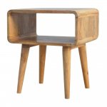
We have a space in the bungalow (small extension on the back) we use as something of a garden room. It has been christened ‘Nana’s Nook’ and currently has an old ikea laundry basket as a coffee table. This needs to change as it’s too big so my wife decided that this design was appropriate;
IMG_0226.JPG
Something of a ‘marmite’ design in that you like it or hate it. I was more intrigued by how to make it given that the construction is outside my comfort zone and I’ve already posted some ‘how do I’ questions. I was mainly concerned over corner grain direction and was initially going to consider having the corners run in the same direction as the top and bottom but soon realised that this wasn’t realistic, mainly due to the issues surrounding fragility of the sections and tear out during construction.

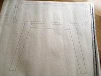
I model most things in sketchup to get an idea of overall proportion and scale but always do a full size drawing before I make anything of size. This is achieved with lining paper and pencil on the dining table. This did actually show that the proposed dimensions were too big and so reductions were made for the final version (‘letterbox’ opening too high). This drawing also serves for production of the cutting list (scribbles top left).
Stuart pic rotated.jpg
I’d always planned to make this out of recycled wood, something I like to do whenever I can because a) I’m tight and b) I like reusing wood where it can have a second life.
IMG_0858.jpg
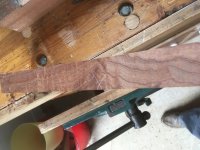
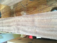
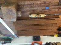
I’m pretty sure this is sapele that started life as a set of stair treads in a school that was demolished to build a fire station. I’ve had it for about 10 years so safe to assume it’s dry! There are a number of holes from fixings etc. but these are worked around reasonably easily.
 
I’m sorry but I don’t know what’s going on here. I’ve posted 3 different photos, in line, in the correct places and this is what’s showing.

I’ve had to type this reply on my ipad as the mac won’t let me back into the thread in edit mode. Appears to take me back to the preview view which of course is useless to me for adding anything further.

Clearly something wrong with my setup (mac running latest monteray). I’ve spent ages drafting a WIP and then struggling to post it in a meaningful, readable way.

Perhaps this WIP is just doomed?!

Sorry again but I think I’ll give up try to post this.
 
Hi Stuart
you've attached all you images but you've clicked on the wrong image for "place inline".

screw it, just add the attachements and let them sit at the bottom from now on. keep going, I like this table and I want to see how you tackled it.
 
Don't give up, Stuart. A lot of us want to see these photos. I think you have to click on the individual photo name, then put the cursor in the right place in the text, and then click on "place inline". I might be wrong as I post my images an entirely different way.
 
Sorted for you Stuart.

A couple of tips
1. As you upload give your photos a meaningful name so you can see which is which
2. When you get in a pickle, go to the forum view and click on Quote. This will show you the underlying code and it will be obvious why you (in this case) inserted 3 copies of the same pic and why the others were left dangling at the bottom - because they had not been inserted.

Cheers
Bob
 
9fingers":gruhvmcx said:
Sorted for you Stuart.

A couple of tips
1. As you upload give your photos a meaningful name so you can see which is which
2. When you get in a pickle, go to the forum view and click on Quote. This will show you the underlying code and it will be obvious why you (in this case) inserted 3 copies of the same pic and why the others were left dangling at the bottom - because they had not been inserted.

Cheers
Bob
But that’s whats so dammed frustrating Bob. I most definitely didn’t insert three copies of the same image and I used the place inline function using the photo numbers which is easy for me as I know where they come from.

I think I’ll resort to some text and a single photo so I can continue.

Thanks for the help.
 
Stuart":3of6i2l2 said:
9fingers":3of6i2l2 said:
Sorted for you Stuart.

A couple of tips
1. As you upload give your photos a meaningful name so you can see which is which
2. When you get in a pickle, go to the forum view and click on Quote. This will show you the underlying code and it will be obvious why you (in this case) inserted 3 copies of the same pic and why the others were left dangling at the bottom - because they had not been inserted.

Cheers
Bob
But that’s whats so dammed frustrating Bob. I most definitely didn’t insert three copies of the same image and I used the place inline function using the photo numbers which is easy for me as I know where they come from.

I think I’ll resort to some text and a single photo so I can continue.

Thanks for the help.

Sorry Stuart but you must have. The evidence was there that showed it. We accept that uploading photos can be a bit fraught rotation wise but everything else works.
Any how like others I'm looking forward to your methods for making this piece as a few others have been attracted to the style but put off by the construction issues.

Bob
 
What's interesting then Bob is how 3 copies got there when only 1 was originally inserted? Somehow my first photo appears to be replicated by however many photos I put in a post.

Anyhow, onwards!

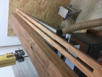
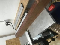
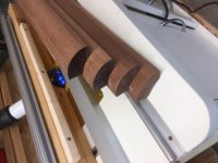
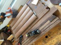
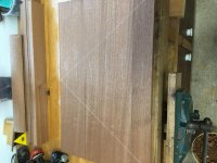
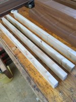
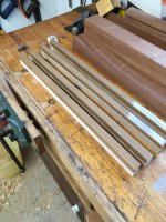
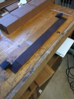
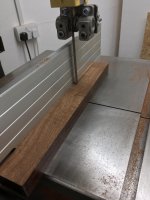
All conversion carried out on the bandsaw fitted with M42 blade (I never use anything else). First cut to remove the old grooves where pieces were joined together then it’s just a matter of a quick run over the planer to provide a decent surface then into full slicing mode on a rinse and repeat basis until I have enough for the cutting list plus a bit of spare.
IMG_0806.JPG
IMG_0807.JPG
IMG_0808.JPG
IMG_0809.JPG
 
Stuart":3fkbr0g5 said:
What's interesting then Bob is how 3 copies got there when only 1 was originally inserted? Somehow my first photo appears to be replicated by however many photos I put in a post.

Not trying to labour the point but there was only one copy of the photo uploaded but the SAME one had been placed inline three times instead of each one inserted inline once each.

Lets draw a line under this and concentrate of the wood work :lol:

Bob
 
I did find some with a wonderful (for sapele!) grain that I thought would be nice to use but it was (for me anyhow!) impossible to plane without massive tearout so I reluctantly abandoned it and went to plainer grain.
IMG_0840.JPG
IMG_0841.JPG
Felt it best to start with the rounded corners as this was the key for this design and any major cockup would mean a different design would need to be adopted!

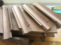
40mm blanks cut and planed to size with an indication of desired shape.
IMG_0824.JPG
I did consider the router table for the ‘outside’ shaping but after due consideration sense kicked in. Using a 40mm round over cutter on my little table would have been interesting I think!
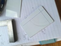
I have a (large) number of id card blanks from where I used to work and thought these would make reasonable templates to aid the process.
IMG_0825.JPG
IMG_0827.JPG
 
Thanks for persisting with the project and the wip.

I'm interested to see how it turns out as a one-off rather than something pressed out in bulk on special formers. I also really like the use of reclaimed wood, kept until the right project comes along.
 
Corners cut off (on table saw) to get close to required shape.
IMG_0832.JPG
IMG_0828 2.JPG
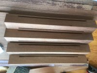
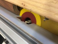
Then (thankfully) had a bit of a eureka moment and realised that I’d need to have grooves on the ‘inside’ edges to allow for a breadboard edge joint between corners and the top and bottom panels to allow for cross grain movement. Achieved with 6mm slot cutter on router table fitted with stops that don’t show in the photo. A fairly quick process.
IMG_0836.JPG
I then squared up the ends of the grooves. Not absolutely certain this was necessary but as I’m not sure at this stage exactly how this joint is going to be set up I thought I’d give myself a bit of wriggle room.
IMG_0839.JPG
IMG_0837.JPG
 
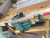
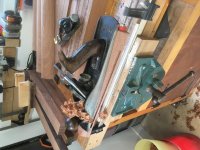
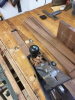
Then it was a case of block planing (one of my favourite planes) to shape.
IMG_0843.JPG
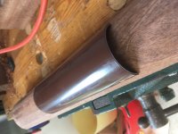
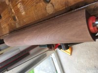
To aid in shaping I made a couple of high tech sanding jigs. Short length of shed downpipes cut in half then heated with the old hot air gun to conform closer to required shape. Sandpaper attached with double sided tape. High quality ergonomic handle hot glued in place.
IMG_0846.JPG
IMG_0845.JPG
IMG_0847.JPG
I sanded to 240 grit which might seem excessive at this stage but that help provide a bit of a ‘shine’ that helped identify flat spots. Not unhappy with the final product which surprisingly didn’t take as long as I feared it might but you can still see vague flat spots. Some final shaping to be done.
IMG_0848.JPG
 
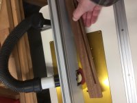
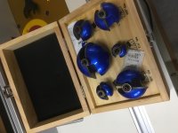
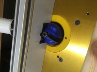
Internal shaping was always going to be on the router table as I already have the correct sized cutter. I think it’s true that cutter sees are generally a waste of money, this set was bought (over 10 years ago) for a particular size and none of the others have ever been used.
IMG_0849.JPG
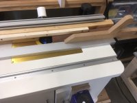
The 25mm cutter was (unsurprisingly) too big for current fence arrangements
IMG_0850.JPG
A piece of CLS was accordingly butchered into submission and with an add on and a ‘front’ restraint I had workable, safe set up. I also had to modify the routers dust extraction to allow for the cutter to drop far enough below the table to take smaller cuts.
IMG_0856.jpg
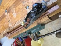
Before starting to cut what were quite big curves a little time with the planes to remove a good chunk of material. I generally enjoy using planes but I now struggle afterwards with a painful shoulder (rotator cuff) but sometimes I’m a glutton for punishment!
IMG_0852.JPG
 
It is probably too late to say this... But looking at your pictures so far, one way to proceed might be to get all four sides dry fitted into the grooves while the corner pieces are still square (or faceted). You could even glue up the top and bottom or the two ends, before doing any of the shaping. That way you keep a reference surface for getting the shaping symmetrical and possibly avoid a clamping challenge.

But it depends on how you are doing the shaping too.

Ah, you posted while I was typing and have solved all the challenges!

I really like the sanding jig, that's genius. :obscene-drinkingcheers:
 
I’m never greedy when routing and with a cutter this big it was a case of small incremental raising to achieve the desired radius. I lost count of the number of passes but it all went smoothly and safely.
IMG_0859 2.JPG
The modified dust extraction meant not all waste was removed!
IMG_0861.JPG
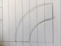
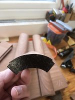
WooHoo, I thought. Finished corners. However, they just didn’t look quite right so I drew the required profile and then traced what I’d produced over that.
IMG_0863.JPG
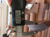
You can see I wasn’t quite there and application of the callipers showed how far out I was.
IMG_0864.JPG
IMG_0865.JPG
 
Not the end of the world and I’d rather be in this position than having removed too much. Back to the block plane and sanding. There’s almost certainly some final shaping to do but as things currently stand I really quite pleased with where this has ended up.
IMG_0867.JPG
IMG_0868.JPG
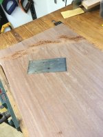
Then it’s on to the top and bottom. Considering sapele is fairly plain grain I spent quite a bit of time selecting what to me was a reasonable layout before marking up for dominoes.
IMG_0869.JPG
That’s progress to date, brought to something of a halt whilst my addled brain deals with the move from windows to Mac (and a good possible explanation for some of my picture issues!).

I have to say, so far I'm reasonably pleased with progress and I look to have 4 usable, round corners. It also appears that the cock up fairy hasn't (yet) visited although there is time!

More to come over the next few days and weeks.
 
Great WIP, Stuart and like the sanding jig. Glad I'm not the only one with problems with concentric circles !
 
Well done Stuart. Thanks for sticking at it.

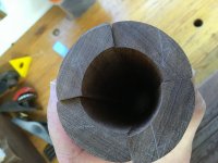
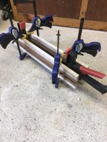
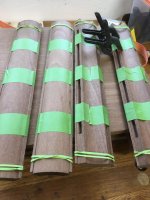
That photo of the 4 pieces held together in a near-tube shows that we missed a fairly obvious suggestion when talking about making these bits. No-one, I don't think, suggested gluing the blanks all togther and turning them on a lathe, yet that would probably have produced the most accurate result. Boring out might have been a bit of a task, though.
 
:text-goodpost:

I've only just seen this thread for some reason. Lathe was indeed surely the way to go. I share your pain Stuart with picture placement and rotation. Nice WIP. Will be interested to see your jointing solutions.
 
I think a lathe may have been an option, but the approach Stuart has taken is as good if not better in many respects. first up being potential tear out issues, the other being your stated difficulty boring out.

I'm really impressed with the finish and think it's a great looking piece, I really like the "bread board" ish join, I'd have been tempted to use biscuits. :lol:
 
Thank you for the encouraging words, with people watching I really do have to get this right!

I'm not convinced a lathe turned set of corners wouldn't have provided another set of issues. The size of the bit and the depth required (40mm x 320mm) would have made it a bit of a challenge and separating accurately in to 4 parts would also make life interesting. I'm not (currently!) unhappy with what I've got or how I got here, it was in fact much easier than I'd envisaged.

Todays adventures. Cutting dominoes and gluing up the top and bottom panels.

Years ago I made some panel clamping aids (I can't for the life of me remember the proper name! - cauls?) but as they've been in storage for quite a while they'd moved considerably so I decided to shorten them, re-plane the desired gentle curve and reapply parcel tape to prevent adhesive sticking.
IMG_0871.JPG
IMG_0873.JPG
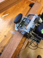
Then it was time to cut for the dominoes (4mm). I bought the machine a while ago and whilst it doesn't get masses of uses I find it much more accurate than my biscuit jointer. I taped a thiner piece of scrap to the bench and with a couple of bench stops (old black & decker plastic ones) I had a decent set up.
IMG_0875.JPG
IMG_0874.JPG
IMG_0876.JPG
I have one domino set to the tight fitting and the others to a slack setting. I find this gives the accuracy I want but a slightly more relaxed glue up not having to fight to get dominoes in their respective slots.
Then it was time to glue up! Nothing fancy, just PVA but had to work fairly quick as there's 5 joints per piece and dominoes to insert. Completely uneventful which leaves me worrying even more about a visit from the cock-up fairy!
IMG_0877.JPG
And relax!

Edit - Andy, rotating and saving then rotating back again seems to post pictures as intended!
 
Cleaning up squeeze out and a light plane for the top and bottom.
ECC89037-2D83-4177-B509-C11565947FE1.jpeg
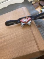
Unfortunately, it started to tear out so I had to resort to my favourite, battered scraper
D029612B-7166-46CB-96DD-B36B113282EC.jpeg4A4D286E-BE80-4D6A-AFB3-99389025E91F.jpeg
Sanded to 120 using a mirka pad. I love it as it helps keep a nice flat surface. I know an ordinary block is just as good but I’ve got this so why not? With mirka ‘paper’ it’s a brilliant bit of kit.
0679A1D7-22B4-40D1-81B7-48568A09E222.jpeg
Cut to size. I pondered long and hard about the breadboard edge and decided to go with a loose tongue as it would be easier to glue the tongue to the round edge and then attach to the top and bottom. I really didn’t feel that trying to attach the tongue breadboard style to the curved edge would work, with only 10mm to play with I could foresee problems.
46524F82-BFBF-44B9-9CAF-D7B80E2C6172.jpeg
Cutting tongues from the previously discarded wild grain bits
D9DEC004-20F2-4792-93CD-863952D3B8CF.jpeg
A bit of a tickle with the plane to make them all fit
B69D481E-C2FF-4E68-96E3-1DC996E936B0.jpeg
C3EAD131-DDDD-49C4-9447-8D53103A4A83.jpeg
Sides were a reasonably simple glue up. Cut over size to allow for a decision on height of the opening.
6EA7539D-7F7D-4AA2-BC30-85F2ECCF0929.jpeg
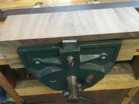
I can’t remember the last time I used the little sticky up doohickey on the front of the vice! Ideal for holding the sides for clean up.
F341A779-78CE-4A48-95D9-05A004895113.jpeg
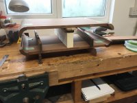
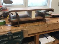
Despite the previous drawing I wasn’t convinced about the height of the opening so decided a sort of mock up was required so a couple of bits of tape later
02BCEB23-C2E0-40CE-9760-E41A6C4C0744.jpeg
F16A0AC5-B7FA-4401-8A3F-0E757FA2895B.jpeg
We’ve decided on the slightly narrower opening which means the sides will be about 55mm so I’m wondering whether they could be ‘fully’ glued instead of breadboarding them?
Any thoughts?
 
Stuart":7fvr4rtn said:
We’ve decided on the slightly narrower opening which means the sides will be about 55mm so I’m wondering whether they could be ‘fully’ glued instead of breadboarding them?
Any thoughts?
Which way is the grain going on the sides? If it's front to back and aligned with the corner pieces, then there's no issue gluing them. If it's up and down, at right angles to the corner pieces, then it's the long dimension across the grain that matters when considering movement, and they'll most likely want breadboards or equivalent.
 
spb":1tk7ojfi said:
Stuart":1tk7ojfi said:
We’ve decided on the slightly narrower opening which means the sides will be about 55mm so I’m wondering whether they could be ‘fully’ glued instead of breadboarding them?
Any thoughts?
Which way is the grain going on the sides? If it's front to back and aligned with the corner pieces, then there's no issue gluing them. If it's up and down, at right angles to the corner pieces, then it's the long dimension across the grain that matters when considering movement, and they'll most likely want breadboards or equivalent.

This is the big problem that others identified with making this type of sleeve and I was hoping to see a solution that removed the movement problem.
Breadboards have never been a favourite technique of mine as it does not fix the expansion problem but instead gives the opportunity to locate the movement in a less visible place.

Bob
 
I don’t think, given the choosen construction method there’s any choice but to go ‘breadboard’. Anything else is almost certainly going to have problems down the road due to movement.

I’m not particularly looking forward to the next stage which is lots of grooving and fitting of tongues but still hopeful (at present!) that if I’m careful it’ll work out.
 
Latest progress. Carefully resetting of the router table to cut the grooves in the top and bottom to match those on the corners.
IMG_0893.JPG
Rinse and repeat for top, bottom and both sides then spent some time squaring up the grooves. I want maximum tongue thickness especially at the edges due to the need to dowel.

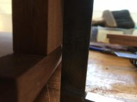
When all that was done time for the first dry fit and lo, - the cock up fairies visit is revealed!
IMG_0894.JPG
At first glance not too bad. Closer examination reveals the issue
IMG_0895.JPG
IMG_0898.JPG
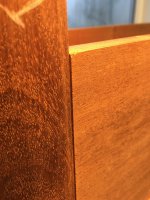
I've clearly removed far too much material on the edges of the corner blocks so in effect they've been 'undercut' and are now smaller than the thickness of the top/bottom.
Fortunately, the inside is actually quite a nice fit,
IMG_0897.JPG
As I see it I have a number of options:

1) Change the design
2) Use filler and paint
3) Sand like crazy and try and 'fair in' the corners with their respective top/bottom/side.
4) Start again and make new corners
5) Let in new edges to the corner blocks

1 and 2 will remain options until I have a finished product! I started off not really keen on the design but have grown to quite like it so I will make every effort to finish as intended. 3 would end up with different shapes to the corners and to me at least, just wouldn't look right.
4 is an option and I have enough wood but a late night bout of insomnia made me think about 5.

Diagrams to explain. This is an exaggeration of existing
side 1.jpg
This is what I'm thinking of doing
Side 2.jpg
By routing out a small amount of the edge I give myself an edge against which I can reference a small piece of matching wood. By planing the shoulder square to the grooved face I can them assemble and 'fair in' the new piece accurately to the top/bottom/sides.
It's a lot of work but I don't see why it shouldn't look acceptable?
If it does all go chest upwards then option 4 comes into play.

Am I mad?
 
That’s annoying. What about option 5 with a contrasting wood instead? If you try to hide it completely and fail, then it would look like a repair attempt rather than a deliberate part of the design.
 
I'd go for contrasting wood, a bit like binding and purfling on a guitar.
 
A while since the last update, progress hasn’t been rapid for all sorts of reasons but I’m getting there.

Contrasting wood was my first thought but given that the finish will include a dark stain (to match an adjacent piece of furniture) I’m not convinced it would be worth it. On that basis I decided on sapele strips as I already had off cuts that would hopefully be a close grain match.

So set up the router to take a shallow cut including a tall front fence to limit movement
E515DE99-B926-43C8-A204-505BC42BE453.jpeg
This gave me the necessary rebates
956556AD-C807-457E-B074-07DD0FB343CA.jpeg
Then glue in the strips and leave to dry
8F754F08-D39E-40C5-B42C-E6AB400E50DC.jpeg
Plane down to size
50044C10-AA46-44AA-AB06-653FEE27DFB0.jpeg
And a trial fit
CE34E63B-06C8-4F14-942D-35BA6C9322F9.jpeg
This gave me the ‘upstand’ that I can plane back after full glue up.
 
Plenty of fettling and dry fits in an attempt to gets nice tight joins.
9B5FFB82-D5D7-4DFB-A64B-F9046FDD4003.jpeg
When happier with the fit I then trimmed the corners close to final size
446E572F-6296-4D92-AB6E-6CC00F8E47CF.jpeg
I was reasonably happy with the way it was going together but paying a price for having the additional strips oversize which prevented getting in as close as I wanted to check the fit.

Then it was dowel manufacturing using one of Petri’s plates. Hitting appropriately sized blanks through resulted in much sapele shrapnel and swearing
4503BA55-DA1E-46D7-87A4-F292793ABCD0.jpeg
So I resorted to spinning them through with a drill and this proved much more successful
DEE39A5E-282C-4790-8F36-186C627F4CAB.jpeg
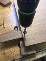
With everything prepared it was time to drill the joints. I ended up using a depth gauge made by my good self when at school. I gave it to my dad and rescued it from his toolbox when he died. Really useful in determining drill depth as I only wanted to have dowels showing on the undersides
60055EF6-824C-4F2A-868B-6FFB83C66DF3.jpeg
Then with suiable depth collar a case of drilling as required using scrap tongue stock to prevent blow out internally
B76A0807-B615-4877-AC81-6977B4488986.jpeg
Careful marking on the tongues (previously glued to the corners) to try and ensure a nice tight pull up when dowels inserted. Middle and end dowel holes elongated to allow for movement
1133312F-797C-4DFF-ACEA-A11AB7B5E9D1.jpeg
The theory being this would eliminate movemat the front and allow it at the rear where it will hopefully be less noticeable.
 
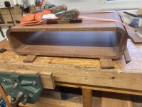
Then the huge fun of the glue up! I decided a single glue up would be stupid so I did it piece by piece to allow for plenty of time (!) to get everything lined up as required. Mostly it worked!
36D400A4-7250-4BD3-8174-432E6B72B431.jpeg
E263FD71-1552-4606-95C2-DF1239B6075F.jpeg
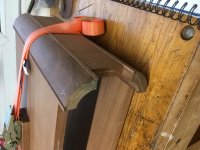
The final piece needed a couple of packing pieces and some strap clamps but was otherwise uneventful
64B8AF1F-F01D-4870-8649-E93EEE5CB812.jpeg
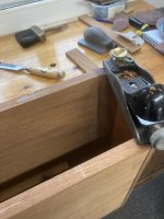
Then light trimming of the edges to ensure it was all lined up
AB17F116-9708-407D-A619-1F846BCF2996.jpeg
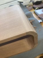
Then trimming down the corners
39AB191B-10F4-4B37-9950-A285CFD75EA5.jpeg
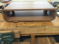
Not too bad a finish
9E7A38D7-B818-4382-AE1F-6D56C37EF299.jpeg
Plenty of sanding and in honesty, some filler (hangs head in shame!)D2DE54C8-069B-4930-9EF9-1F2FF8BD392D.jpeg
Inside
EB3025DF-374B-449C-AD6D-AEBCCA596D2E.jpeg

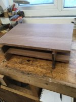
Overall I’m not massively unhappy but a bit pee’d off at the cock ups that resulted in less than perfect joinery.
 
It looks pretty darn good from here. I think your persistence is paying off.
 
Back
Top