• Hi all and welcome to TheWoodHaven2 brought into the 21st Century, kicking and screaming! We all have Alasdair to thank for the vast bulk of the heavy lifting to get us here, no more so than me because he's taken away a huge burden of responsibility from my shoulders and brought us to this new shiny home, with all your previous content (hopefully) still intact! Please peruse and feed back. There is still plenty to do, like changing the colour scheme, adding the banner graphic, tweaking the odd setting here and there so I have added a new thread in the 'Technical Issues, Bugs and Feature Requests' forum for you to add any issues you find, any missing settings or just anything you'd like to see added/removed from the feature set that Xenforo offers. We will get to everything over the coming weeks so please be patient, but add anything at all to the thread I mention above and we promise to get to them over the next few days/weeks/months. In the meantime, please enjoy!

Servant Bell Board

NickM

Old Oak
Joined
Dec 8, 2020
Messages
1,545
Reaction score
858
Location
Near Basingstoke
A little project I'm about to make a start on (actually, restart) is to "restore" a servant bell board which used to be in our house.

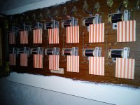
When we moved in four and bit years ago, the bell board was in a stable. The glass had been smashed and it generally looked in a sorry state.

This is it after removal of the worst of the cobwebs.

IMG_0465.jpeg

Unfortunately the glass was broken.

IMG_0464.jpeg
 
My original plan was simply to get it to the point when it could be hung on the wall as an ornament and as part of the history of the house.

However, after cleaning it up a bit, a quick test with a battery revealed that all of the electromagnets were in working order so it seemed a shame not to do a bit more with it. Although we have found some evidence of the original wiring, we don't even know where the box was placed and getting the whole house re-wired seemed a bit OTT!

The vague plan was therefore to come up with some kind of wireless solution where bells could be rung from, say, an app on a phone. I would also like in due course to repurpose some of the few remaining wall buttons and the front door bell to operate it wirelessly.
 
The first problem was the broken glass. I got a quote for getting it redone properly and it was quite expensive (I can't remember exactly how much off the top of my head but it was a few hundred). If I can complete the project, I might actually get it done, but in the meantime I decided to have a got at it with paint (rather than the gold leaf it should have).

After tracing the original onto a new piece of glass, my gold paint pen and black acrylic paint came up with this:

IMG_5241.jpeg

It actually looks a bit naff, but I think it's OK. Normally when it's up on the wall you aren't so close to it and it looks reasonable. I've still got the original glass and I will consider getting it properly done one day.

I had also cleaned it up a bit and put some fresh finish on it.
 
The next stage was to try to get it working. I did manage to do that using a Sonoff WiFi switch which has inbuilt relays. That was powered by a mains adapter with the power for the bell board being provided by a 9v battery.

The downside was that it could only operate 4 bells, had a battery which needed to be recharged and, with the battery, couldn't be packaged up very small.

All of this was around 3 years ago and I haven't done anything since then until the Christmas holidays.

Over the holidays, my son and I had a go at using a WiFi Arduino board (an ESP8266 for those in the know) and a relay board to see if we could do something useful with that. I'll need to take some photos of the set up, but we have managed to get it to work 10 bells. The 11th will be the front door bell which we need to tackle separately).

It currently works by putting the ISP address of the Arduino into any browser connected to our home network (it works on a phone for example). The Arduino code produces a series of radio buttons on the browser page which operate relays.

That's really as far as I've got. Next steps are:

1. Package up the electronics into a box which can sit behind the bell board. That's where the woodwork will come in.

2. Improve the browser page so the buttons are correctly labelled and try to make them turn off automatically.

3. Turn our attention to some kind of wireless wall buttons and front door bell.

4. See if we can make it work with Alexa. We did try that initially. We made a bit of progress but hit a brick wall and moved to the browser based approach.

That's all for now, although I'll try to take some photos of the electronics thus far and will also take photos of the woodworking when I make a start on that (which could be a little while).
 
Glad to see you haven’t wasted any time with your first? post, I think what you’ve done with the glass looks very good indeed and as you say no ones going to peer up there and study it, had you got the little bit of glass that appears to be missing you could have stuck it all onto a piece of clear Perspex I suppose.
Sorry but that’s as far as my expertise goes, over to somebody else for the electronics. Ian
 
Nick,

I have a requirement to use an ESP8266 as a webserver with the ability to read an analogue value (using its ADC) and the status of a relay, then send that to a browser mainly on my phone. Based on the value returned, I want to make a manual decision then to turn that relay on or off back on the webserver end.

Can you point me to some sort of learning resource or even better a project I can copy, plagurise, learn from for this bi directional application please. I'm just about able to hack arduino code with a bit of guidance but new to the ESP8266
Apologies for hijacking your thread but this is the first time I've bumped into someone who is even near to doing things with ESP8266.

TIA
Bob
 
For the record, I've used the ESP8266 a fair bit over the years, both for hobby stuff (my home brewing fridge and a clock which displays hours and minutes on moving coil meters, for example), and in paid work.
 
John Brown":2qr4209l said:
For the record, I've used the ESP8266 a fair bit over the years, both for hobby stuff (my home brewing fridge and a clock which displays hours and minutes on moving coil meters, for example), and in paid work.

Can you suggest a learning resource, I'd like to try and teach myself if possible.

Thanks
Bob
 
Bob, I can’t point to a specific resource for what you want to do, but I did find some helpful tutorials/code for what I want to do. I found those through google searches. Randomnerdturorials seems to have some good stuff on it. I’m trying to leave the electronics/coding side of things to my son as much as I can!
 
NickM":1nhycni7 said:
Bob, I can’t point to a specific resource for what you want to do, but I did find some helpful tutorials/code for what I want to do. I found those through google searches. Randomnerdturorials seems to have some good stuff on it. I’m trying to leave the electronics/coding side of things to my son as much as I can!
Thanks Nick

Bob
 
To be honest, I've always relied on googling. Usually hit some code on GitHub that helps.
But then I've been writing code for 44 years or so. So while I might be able to help with specific questions, I unfortunately can't steer you towards any online learning resources.
 
Now, Nick, no pressure, but you need to get this working, and post how you did it.

I don't have any ulterior motive other than the encouragement of sensitive restoration.

Ahem. Nothing like this in my house at all. No siree.

Servants' board 1.jpg

Servants' board 2.jpg

And the other thing I want to do is to get the house 'phone working.

House 'phone.jpg

Projects that are not, frankly, given the priority they deserve by the powers that be.
 
What sort of mansions are you guys living in :)

Bell boards :shock: do you have servant quarters too? :)

Great project. I hope you can pull it off.
 
I can remember getting my hands on one of those boards as a kid. I think my dad removed it from a house he was redecorating. I think I mainly just repurposed the copper wire, but they were a bit more commonplace back then.
 
Andyp":brfuqtkn said:
What sort of mansions are you guys living in :)

Bell boards :shock: do you have servant quarters too? :)

Great project. I hope you can pull it off.

It's a largish house; not Downton Abbey! Rumour has it that it was once inhabited by an illegitimate daughter of King Edward VII. I thought that was rather exciting, but it turns out that, like bell boards, it's also quite common! There would have been a housekeeper back in the day - hence the bell board.

When I first got some of the board working, the only person to use it in anger was my wife who used her iPad to ring it from the bathroom with a request for a cup of tea! I have wondered about repurposing one of the bells as "Workshop" so I can call for refreshment, but I know that nobody would respond...
 
I'm sorry for not posting any pictures of the electronics yet. It's a birds nest at the moment and now that I've started on the box, I thought I'd wait until I've laid everything out a bit better.

This is what I've done on the box so far. (I'm afraid the following will be basic stuff for most of you, but it might be of help to someone. I'm also very open to constructive criticism of my technique so hopefully I'll learn something too.)

I started with a detailed drawing of what I wanted to achieve:

IMG_8093.jpeg

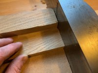
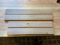
I had some offcuts from another project which were already the right thickness (around 12mm) and were wide enough. I marked the width and planed them to the line. I then set about shooting one end square, measuring the length from that, marking with a knife all round, and cross cutting close to the line:

IMG_8082.jpeg

The Japanese saw was a birthday present from my parents and I rather like it.

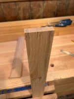
I then shot the end square and to the line. I used the "Rob Cosman method" (I'm sure it's not his really but I saw it one of his videos) of planing a chamfer on the back end down to the line and then planing until the chamfer disappears with the last stroke.

IMG_8083.jpeg

IMG_8084.jpeg

IMG_8085.jpeg

For the opposite piece, I measured the length of the first one to try to get a matching pair.

IMG_8086.jpeg

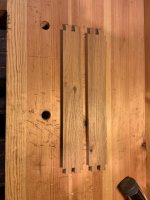
When I'd finished, I had these pieces ready for dovetailing:

IMG_8087.jpeg
 
Next up was marking out and cutting the tails. The tails were on the vertical pieces of the box so that the bottom can't drop out.

I started by laying out the tails on the end grain, doing both pieces at the same time to get consistency:

IMG_8089.jpeg

I then marked the tails on the face of the board (I used a veritas dovetail marker which I got for Christmas to replace the very rough and ready one I made last year):

IMG_8090.jpeg

At some point I had marked the thickness of the boards around the ends of each piece with a marking gauge.

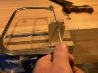
Next I sawed the tails. I've been trying to put the piece square in the vice to see if that helps with accuracy (it certainly didn't do any harm).

IMG_8091.jpeg

IMG_8092.jpeg

I then made a small chisel wall to saw the shoulder:

IMG_8094.jpeg

IMG_8095.jpeg

IMG_8096.jpeg

I try to saw to the line with these but needed to do some very light paring (which, based on the other thread on that topic, I should probably be taking more care over). I did work out that I get a much better result from the saw if saw to the left of the line so that my thumb is pushing the saw towards the wall (if that makes sense).

I then removed the waste between the tails with a coping saw and chiselled back to the line:

IMG_8097.jpeg

IMG_8098.jpeg

IMG_8099.jpeg

So far so good...
 
Nice, Nick.

I bought a little square like yours from Ebay a few months back, for the one specific job of checking squareness of an edge when I was shooting. It had every single possible fault that there is! Both bits of steel were tapered (ie the edges were non-parallel). None of the angles, internally or externally, were even close to 90 degrees. So I did a little filing (it was as soft as anything), and now, for £3.00-something and a bit of effort, I have a perfectly good little tool. I say this just to make you go and check yours again carefully!! :)
 
On to the pin boards.

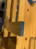
I decided to use the blue tape method mentioned on some other recent threads (I've tried green tape in the past with some success but thought blue might be better - it's certainly a darn sight cheaper than the green frog tape I had when I tried this method previously).

IMG_8100.jpeg

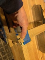
I put the pin board in the vice flush with a plane which I then used to support the tail board. I tried using another board to help square everything up.

IMG_8101.jpeg

On a second attempt, I tried using a square held against the gauge line to get everything square and also to get the right fore/aft alignment. It's. bit of a faff but did work. The tape operated as an extra hand.

IMG_8107.jpeg

IMG_8108.jpeg

I marked with a knife, removed the tape from the waste and extended the line down:

IMG_8102.jpeg

I then sawed the pins. I deliberately stayed away from the lines on this attempt and then trying paring back to the lines. Unfortunately the result was some gaps so on the later attempts I sawed right next to the line and they fitted better straight off the saw.

IMG_8103.jpeg

In my annoyance at the gaps, I didn't take any pictures, but I decided they were capable of being repaired.
 
Mike G":clm90j58 said:
Nice, Nick.

I bought a little square like yours from Ebay a few months back, for the one specific job of checking squareness of an edge when I was shooting. It had every single possible fault that there is! Both bits of steel were tapered (ie the edges were non-parallel). None of the angles, internally or externally, were even close to 90 degrees. So I did a little filing (it was as soft as anything), and now, for £3.00-something and a bit of effort, I have a perfectly good little tool. I say this just to make you go and check yours again carefully!! :)

Thanks Mike. Mine (a bit, but not much, more expensive from Axminster) seems to be OK but I will check it again! I really like having a small square to hand - it's very convenient to use.
 
Next job was to turn it into a box. That involved making a stopped rebate all the way around. I did this on the router table - each piece individually taking care to start and stop in the right place on the pin boards. One pin did break but I was incredibly lucky to find the piece the next day so I could repair it!

That got me to this:

IMG_8113.jpeg

I then cut a piece of 12mm ply and fitted it to the hole, before adding a rebate to that so it would drop right in.

IMG_8114.jpeg

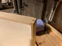
I left the box sides proud and then planed them down. I didn't quite go flush with the ply because the bell board will go on that side and I didn't want any gaps (e.g. if there was a slight crown in the ply).

IMG_8117.jpeg

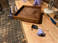
I then dealt with repairing the gaps in the dovetails and cleaned everything up with plane and card scraper. Finally, I had a go at staining it. I didn't make a proper attempt to get it an exact match with the bell board but thought that some van dyke crystal mix I already had would be close (maybe... I suspect the bell board is much more red in colour). I raised the grain with water and sanded back (400) before staining.

IMG_8119.jpeg

I'm not too worried about the inside as that won't be seen unless the box is opened.

That's as far as I've got. The next jobs are to figure out how to mount the billboard to the box and start laying out the electronics. I also need to make a board which will attach to the wall and on which the box will be attache (on hinges). I think I will make the backboard big enough to mount the separate bell as well.
 
I finally got round to continuing the wooden aspects of this project.

Having done the "box" for the electronics, the next step was to make the "lid". In actually fact, the lid is really a board which will screw to the wall. The box will be hinged on to that.

First step was to glue up three lengths of oak to make the wide board. I didn't photograph that but I used the planer/thicknesser to do the donkey work and hand planed the edges square and flat to then glue it together. I then scraped the glue and generally tidied them up with my Stanley scraper:

IMG_8174.jpeg

I then made sure one edge was square and flat and used that to mark off the edges with a knife. I then routed a fielded profile all the way round. The raised field gives room for the hinges:

IMG_8175.jpeg

I then cut the hinge mortises.

IMG_8176.jpeg
 
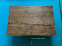
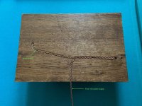
Some of the wires (main power and wire to the bell) need to run behind the board. I drilled holes where the wires go into the board and back out again and then drew lines where I would rout channels for the wires to run in:

IMG_8177.jpeg

I recently fitted a little tail vice (veritas inset one which my parents gave me for Christmas) and dog holes on my bench and thought it would be rude not to get some holdfasts which gave me a good stable base for routing:

IMG_8178.jpeg

As you can see, my handheld routing skills are unparalleled (or perhaps just unparallel) but it should do the trick:

IMG_8181.jpeg
 
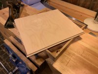
This is the board with the box fitted. The board has now been stained and I'm giving it a few coats of oil.

IMG_8179.jpeg

IMG_8180.jpeg

I'm now wondering if I should have the grain on the board running the other way so that I don't get movement between the hinges. Oh well, I'll see what happens...
 
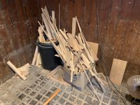
On a separate note, I cleared out the fire wood shed a bit and put up some shelving for storing the real wood.

IMG_8170.jpeg

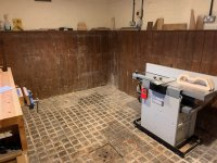
This meant my workshop went from this (it was actually a lot worse but I didn't take a picture of the starting point)...:

IMG_8155.jpeg

...to this:

IMG_8156.jpeg
 
Malc2098":2s67famo said:
:D You've got far too much floor space!!

I've obviously got an estate agent's camera as it looks bigger than it is.

I'm intending to build a small unit to go against the wall there. My plan is to have it as a sharpening table, perhaps with a small metal working vice for the odd job as well. Basically somewhere for the dirty jobs. It will have some drawers and cupboard space underneath.

I also want to build it as a way of practicing/learning a few skills. My plan is to build it using traditional joints etc.

The only problem is that I'm really struggling to get timber at the moment with lockdown in full swing. It's getting frustrating!
 
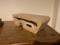
Oh, and in case you're wondering what the odd shapes are on the planer, they're sections of a scale model of my son's GCSE DT project which he has been designing and which I've given him a little help building (mainly I did the template routing as I wasn't going to let him loose on the router table - I find it scary enough using it myself).

It's a coffee table which, in the right setting, could look quite cool I think.

IMG_8184.jpeg
 
My son and I did the wiring for this last night.

To start, here's a photo of the bellboard mounted on the new pieces I've been making:

IMG_8192.jpeg

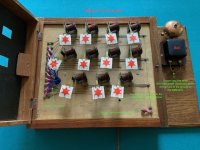
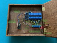
We mounted the electronics and then wired it up as follows:

IMG_8189.jpeg

IMG_8194.jpeg

IMG_8188.jpeg

The last job on the wiring is to solder the "posh wire" into the 12v power adapter. We can then give it a test. At the moment we have a basic code running on the arduino which allows us to operate the bells with "radio" buttons from a web browser. I'll show some pictures of that when we have it running again and will attempt to explain how the code works.

I then want to modify the code to change the labels to match the rooms on the bellboard and generally personalise it a bit. That will be a leap into the unknown for me...

Later improvements will be investigating how we can get remote switches to operate the bells (including the front door).
 

Attachments

  • IMG_8194 (1).jpeg
    IMG_8194 (1).jpeg
    136.2 KB · Views: 2,931
  • IMG_8189.jpeg
    IMG_8189.jpeg
    473.6 KB · Views: 2,931
  • IMG_8188.jpeg
    IMG_8188.jpeg
    441.2 KB · Views: 2,931
Last post to wrap this one up (at least for the time being).

The gist of the code is as follows:

- When you switch on the arduino the code connects it to your wifi network.
- By having the arduino connected to a PC you can (through a serial hub) read the IP address it outputs.
- Putting the IP address into any browser connected to the same network brings up this page. The code fon the arduino populates the browser page.

IMG_8196.jpeg

- Pressing the button on the page activates an output pin on the arduino which in turn fires the relay thus closing the circuit triggering the relevant electromagnet on the bell board and ringing the bell.
- The buttons automatically reset after a second or so, turning the bell off.

We found the code on the internet (GitHub I think) which did the vast majority of what we needed it to do. It very easily allowed you to specify the number of relays you wanted to operate. The changes we had to make were including our WiFi log on details, assigning an arduino pinout to each relay, and personalising the browser page by adding a heading and labelling the buttons with the room names. The last of these was the nearest we came to real coding but it actually turned out to be very easy... for my son, who deployed his GCSE computer science skills!

As mentioned before, future additions will be to have a front door bell which rings the appropriate flag on the board, and to have working wall buttons in some rooms (I think two of the rooms still have the button on the wall which I'd like to get working.

None of this is remotely useful, but it seems better than having the bell board languishing in a shed and it has been fun to combine some old and new technology and to wrk on it with my son.
 
Nice mix of old and new tech there — I remember a similar board in my grandmas house growing up — though that was still in its analogue incarnation!
 
Back
Top