• Hi all and welcome to TheWoodHaven2 brought into the 21st Century, kicking and screaming! We all have Alasdair to thank for the vast bulk of the heavy lifting to get us here, no more so than me because he's taken away a huge burden of responsibility from my shoulders and brought us to this new shiny home, with all your previous content (hopefully) still intact! Please peruse and feed back. There is still plenty to do, like changing the colour scheme, adding the banner graphic, tweaking the odd setting here and there so I have added a new thread in the 'Technical Issues, Bugs and Feature Requests' forum for you to add any issues you find, any missing settings or just anything you'd like to see added/removed from the feature set that Xenforo offers. We will get to everything over the coming weeks so please be patient, but add anything at all to the thread I mention above and we promise to get to them over the next few days/weeks/months. In the meantime, please enjoy!

Two Concert Ukuleles (More or Less Finished)

Malc2098

Sequoia
Joined
Jul 3, 2016
Messages
8,382
Reaction score
1,470
Location
Tiverton
Name
Malcolm
Having got my CNC Router mostly up and running and consolidated all my notes and memories from the internship course I took in June, I've started work on two Concert Ukuleles.

For the bodies, I call be using the Sevenoaks Sycamore I acquired recently. I shall be using the lamination technique for the sides that I learnt on the course.

For the neck, I shall be using a laminating technique to both add strength and stability, and added appearance.

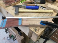
So, I first had to choose what timbers to use for the main structure and the laminations of the neck.D1BC1F3E-78CC-4835-97D3-754B837E00AF.jpeg
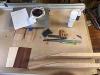
I had an assortment I'd acquired over the years; Mahogany of sorts, Maple and Padauk. These were the lengths I chose.2B7E5202-D54F-4C57-B3C1-3BAF547B2716.jpeg

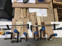
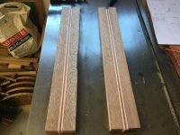
By ripping the not quite QS mahogany strip down the middle, turning one of the sides end to end and placing the contrasting strips in between them, I'm told that any potential twisting stresses in the mahogany are neutralised.684674E5-C59B-4801-8551-16DE6277C3A4.jpeg
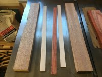
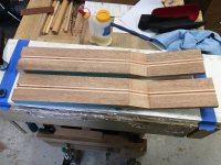
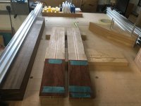
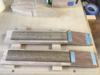
So, here they are after gluing and truing.8D361DD6-72B3-4D62-938F-F84B8B1688DC.jpeg
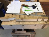
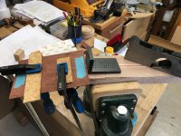
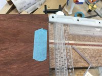
The next part of the process is to cut the scarf joint for the headstock and the butt joints for the heel. In order to test my method out against the drawings, I made a dummy run with some leftover batten from a previous job.
CADAB0B3-69D3-4B77-B30C-B06EA7E9F037.jpeg
905743D8-860C-4E66-BF3F-F08DF8E065F0.jpeg

I've checked the measurements against the plan and it all fits. But now, it all comes to a stop for a time, while we have the grandchildren staying for a week.

I've also got some CNC jigging to do, too; a 12' radius 450mm wide sanding dish, 14 degree wedges to facilitate the scarf cut on the bandsaw and also to support the angled headstock on the CNC for further machining.

Back in a week or so.
 
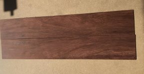
I brought back a Granadillo fretboard from the course in June. I chose it for my fretboard because of the swirl, but that swirl caused it to twist, so we didn't use it. So I've resawn it into book matched veneer and it will become the headstock veneers.IMG_7260.jpg
 
Neck Scarf joint - see what I did there.

It is considered stronger to create a scarf joint with a ukulele or guitar neck, rather than carve out of one piece. So here goes the scarf.

This scarf angle will be 13 degrees. So I need and accurate jig/form/wedge to assist in the supporting and shaping of two parts to make a 13 degree angle headstock.

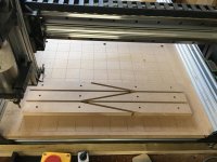
Firstly I cut a number of 13 degree wedges from 18mm MDF with 6mm locating holes on the CNC router.C91ED496-E1FF-441E-BCF9-A7DF5B48533B.jpeg

Then using 6mm aluminium tube from B&Q I joined them together and tested them against the angle gauge.B54715F5-8E50-4F55-AC35-EE27CEE48F02.jpeg

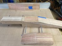
Next, I separated the six wedges to make a 13 degree offset guide for the bandsaw, and set it up with the stock.074F1456-3EE1-4699-954A-FF30D7AA5373.jpeg56BFD23D-D43F-4043-B305-91F87D3F79E2.jpeg

They were all stuck together with DST. These were the two cut stock necks.763FA573-DFCB-4157-9885-9D393906162E.jpeg

Using the wedges again, I can set the neck side up level on the CNC and use a bottom cleaning bit to perfectly level that half of the joint, and when that's done, place the headstock on it to clean that other half of the joint.CE934219-6146-4D70-88F7-248B5B9F6C00.jpeg

And although the joint isn't glued, this shot indicates how the headstock and neck will be supported when machining the headstock.EFF22AFE-7001-4628-8E81-7A17403F4B07.jpeg
 
After all the effort to get that CNC up and running it most be very satisfying to see it begin to pay its way. Great stuff.
 
Having got the 13 degree wedges working I now use them to support the two necks and two headstocks to machine the sawn surfaces of the scarf joints.

I used masking tape and CA glue to secure the wedges to the spoil board and themselves and then the same for the neck to the wedges. The gluing surfaces were now parallel with the spoilboard and therefore with the underside of the cutter.

I set the machine up to cut 0.2mm down front Z axis zero where it touched the sawn surface. This is the video of just one of the necks.

https://youtu.be/CLwNjDlgdo8

[youtubessl]CLwNjDlgdo8[/youtubessl]

The resulting pieces ready for glue up.708BE08B-BE87-46E0-92F5-11CE44B5F841_1_201_a.jpeg
 
That's seriously cool, Malcolm! I'm wondering how long you sat thinking about how to design and cut the jig - as well as cutting and planing the headstock pieces. It must have been a fun problem to ponder.
 
Thanks, Gents.

Peter F, my CAD/CAM software is only 2D and 2.5D. Not 3D. So I have to think of a ways to create something that can become 3D by using 2D design. The wedges on their sides were 2D, especially with holes through them, and that was the best way to get an accurate angle. Once machined, turn them up on edge and they become 3D. The pro on the course I recently completed, when showing me how to rasp the curved section of the neck, said something like, 'Don't use the rasp in curved strokes to create a 3D shape. Use it in 2d straight strokes at successive angles to create a 3D shape.' Hopefully I can show that later in this build.

Next, I've got to reduce the headstock thickness to 10mm to accept it's veneers.66C367EF-153F-4137-92C2-FCE5A1DA9C95.jpeg

Both headstocks sawn to thickness and one pair of book matched veneers ready.ECA23DE5-C718-4CDF-B9C6-10950945323E.jpeg

While the second pair of book matched veneers are butt joined.B96CE08E-28DD-4710-B9FB-F9AE442393EC_1_201_a.jpeg

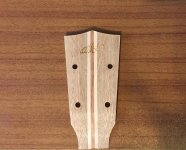
The veneers are Maple and Granadillo. The maple will provide a 1mm contrast stripe between the Mahogany of the headstock and Granadillo veneer.
 
Following with interest but nothing constructive to add.

I seem to have reached the point where everything wooden has already been made so proper projects are sadly lacking here. Still like the idea of a CNC but nothing to make if I had one. Just have to keep watching you :)
 
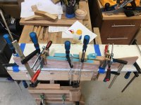
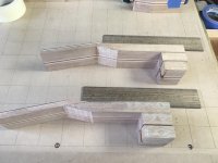
Using a goodly number of clamps to glue tiny angled headstocks to a their necks, making sure the the laminations all line up where they are to be seen.

6A74ED9D-8429-4B9C-97BF-9B43E33DE718.jpeg
 
The glue up seems to have been successful with no sideways sliding. I've bandsawn off an angle at the location of the volute.

3C18B8E3-2AAE-4545-9AB4-634A747F5258.jpeg

From now on, much, if not all of the instrument is referenced off a centre line. I've trued up the scarf to the neck with the No 6. I've clamped the Granadillo/Maple sandwich on the centre line, but placed higher up the angle to shoot the end square to the neck. The bone nut will be fitted in between the headstock veneer sandwich and the fretboard.

82998A5C-6322-49BB-BBF5-4C2378970CE4.jpeg
206BE2AD-3082-4995-B531-AFD7C6B21C4B.jpeg

Years ago, and I really mean decades ago, when I first started out making instruments and was even poorer then than I am now, I used to look for alternative sources of tone wood. One source I found was turning blanks. I found this lovely quarter sawn blank of Ovangkol at a place we all know in Somerset! I doubt I can get one for that price now!

E88DB86A-3972-4D1C-92CC-43FC6245A067.jpeg
CB00106A-FE28-4EE1-A6EC-1FA706D717D1.jpeg

I reckon I should be able to get about 4 decent fretboards from the blank.
 
The headstock veneers have been shot (shooted? :) ) Square to the centre line and perpendicular to the face of the neck to abut the back of the nut.

24968E58-524C-459A-9876-EFAC650185C9.jpeg

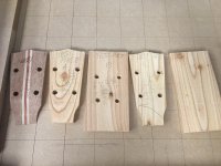
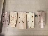
Both headstocks have been finished to the dimensions of the CNC headstock jig, which isn't even made yet (but drawn in CAD), which will hold the headstock in place while fixing holes are machined concentric with the machine head ferrule holes, machine the overall shape of the headstock, machine the logo pocket, and finally machine the ferrule holes.

6B01FC81-94E6-4E83-802B-EC266D4EAB1E.jpeg

A lovely looking length of Ovangkol has been ripped, then sanded to thickness and divided between the two necks.

5E46C415-E5B2-46F2-9C47-E53493AC5B90_1_201_a.jpeg

Cutting the overlength neck stock allows me to make up the heel stock ready for gluing before the overall carving of the neck.

05332DE4-4C4A-4EB7-B434-84046260823C_1_201_a.jpeg

I'm hoping those laminated strips will look good through the carved curve of the heel.
 
Truss rod slots routed. I think carbon fibre rods might be a little disproportionate, engineering and cost wise, but 10mm aluminium box section from B&Q isn't.

379B3B2D-EE59-4603-B690-B0691D97CCCE.jpeg7FF05FB0-CC99-4A0B-BE59-2E2B8433EFA4.jpeg

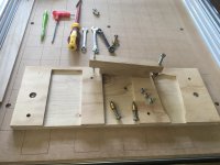
I managed to draw the headstock jig in my CAD/CAM software. The point of the headstock jig is so that I can repeat the process of machining headstocks with accuracy each time. I am not proficient enough to be able to achieve that with hand tools alone.

3875A153-C7A7-4FE0-A575-2DD268944B98_1_201_a.jpeg

The two outer holes bolt the jig to the spoilboard, so it will always go back into the same position.
The left, middle and right positions locate the headstock during the machining process.
The two holes either side of the left position allow fixtures to clamp the headstock down, while the CNC machine drills four pilot holes for the tuner ferrules.
The two holes in the middle position hold the headstock by screwing through two of the aforementioned holes into threaded inserts in the jig.
While in the middle position, the CNC machine carves the shape of the headstock, and also mills the logo pocket.
In the right hand position, the shaped head is head by two clamps and the tuner ferrule holes are milled to size.

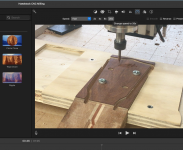
This is the CNC simulation of the machining of the jig. I will have to draw separate tool paths for the headstock holes, logo pocket and shaping.

https://youtu.be/ACUtmOXFR3U


[youtubessl]ACUtmOXFR3U[/youtubessl]
 
Very good, I have run a first bit of G code to cut the holes in the job and the screwed it down for the rest of the cuts.
 
DaveL":1mar9fxt said:
Very good, I have run a first bit of G code to cut the holes in the job and the screwed it down for the rest of the cuts.

Thanks, Dave. I might well just do that. That will co-locate the jig holes to the spoilboard. I've created each of the toolpaths as separate files, so it'll be a doddle to do that.

I have always succeeded with blue masking tape and CA glue, so long as I both burnish the masking tape and use accelerator on one side and the glue on the other.
 
Remember this?

3875A153-C7A7-4FE0-A575-2DD268944B98_1_201_a.jpeg


Now it's this.

9E500D44-A311-483C-B705-75F15BFFD236.jpeg
I made a jig to insert the threaded inserts vertically into their pilot holes.

And this is how the headstock jig will work.

AB7F010A-C8CB-487A-B092-1BEE8137864D_1_201_a.jpeg

The first position will hold the headstock in place while four pilot holes are drilled coaxial with the tuner holes

The second position will use two of those holes to secure the headstock while the logo pocket is milled. I will continue to use my signature as the logo. The Mother of Pearl is waiting for some hide glue so that I can secure it to a spoil board, then remove it with some hot water after the logo profile is milled.

The second position will also be where the profile of the headstock is milled.

The third position holds the shaped headstock in place while the tuner holes are milled to the diameter of the tuner ferrules.
 
Coming along nicely.

First thought is that position 1 and 2 could be done in the same location. Drill the holes to just deep enough then put screws in to inserts in the jig and take the clamps away.
 
Thanks, Robert.

I followed the design from the pro running the course I went on. I suppose that it could be done like that, but each time you change the design, as a result of different length machine head shafts and therefore thicker headstock, then you'd have to be absolutely certain the drill milling bit doesn't descent onto the inserts.

At least this way, if that happens, it's only into plywood.
 
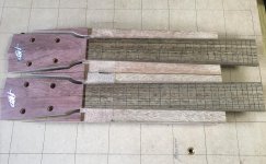
Today I managed to mill the two fretboards. They were drawn in the CAD/CAM software to the accurate gaps between each. The slot cutter is 0.6mm in diameter and cut two passes at 0.5mm deep each. The slots are stopped before the edges. I have a little tool that neatly cuts the end of the fret tang off so that when fitted, the ends of the fret tangs are not visible. I don't think I would ever have been able to cut stopped slots by hand.

The profile was cit with a 3mm cutter.

I sped the videos up a little bit. ;)

https://youtu.be/k0svBFc5U9Q

[youtubessl]k0svBFc5U9Q[/youtubessl]
 
Interesting.

I used to make guitar fretboards with edge bandings to hide the fret ends. This is a good and very accurate solution if you don't want to do that.
 
AJB Temple":53wpbnyk said:
Interesting.

I used to make guitar fretboards with edge bandings to hide the fret ends. This is a good and very accurate solution if you don't want to do that.

I've done that, too. I much prefer this way.
 
Not surprised Malc. CNC gear was not a DIY thing when I was doing it. And I did not have your CNC build capability. Also many guitars, especially electric, tend to have matched banding down the neck and around the body.
 
Had I not been on the ukulele making course earlier in the year, I would never have thought of doing this. But with the Cad/Cam software that I use and the machine that I built, even at the size that it is, it can mill two facsimile signatures from a 44mm x 22mm x 1mm thick piece of Mother of Pearl.

Importing my signature onto that piece would only mean space for one item, but by using to software to rotate the signature and then flipping a copy, I managed to fit two onto that tiny piece of shell.

I must confess, not having much experience at this, that while it was milling and I was holding the extraction hose, my nerves were shot expecting either the cutter to break or the shell to shatter.

But I designed the toolpaths to pass 10 times through the material, that is 0.1mm each pass with a ramp of 1mm long from the end of one pass to the next which worked.

Now, all that I have left to do is equally successfully create the pockets in the headstocks to receive these.

https://youtu.be/AA_uDJq29Hs


[youtubessl]AA_uDJq29Hs[/youtubessl]
 
I think I would have been nervous of breaking the logo getting it off the backer well done, they look great.
 
How are doing that Malc? It looks like the MOP is stuck down, pattern cut, then glue melted to release the logo?.
Impressive.
 
Thanks, Gents.

Dave, I was! I was panicking until I remembered the heat gun.

Andy, the glue is Titebond Hide Glue which is reversible. I left it to cure overnight and it was rock solid. The water I dribbled onto it was straight from the kettle, but it wasn't enough. It needed the heat gun and the combination of water and heat worked a treat.
 
I’m following this with interest. The CNC has clearly opened up a whole world of possibilities for you!
 
Not everything runs smoothly in the workshop chez Malc2098, in fact quite frequently Anglo Saxon expression can be heard emanating from within.

You may remember I made a jig, that I copied from the one I used on the instrument making course a few months back. Everything worked well on the trials using scrap pieces except one thing.

A0C778A6-8C6E-4490-B625-70FF76960006_1_201_a.jpeg

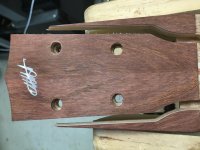
The machine head shaft holes were milled. The machine head ferrule holes were milled, as you can see in the image above, the profile was milled and the MoP signature logo pocket was milled. Although you can't see it from the image, the shaft holes and the ferrule holes are not co-centric (or is that concentric?). They are only about 0.5mm out, but that is sufficient to make it impossible for the machine heads to fit.

I did manage to bore the shaft holes out by an extra mm to the side where the ferrule hole sat, and that enabled the machine head to fit, but that was a hack and not a solution to the CNC problem. The software showed the holes were in line with each other and all things being equal should share the same centres.

So I set up a number of trial pieces and experimented with tool paths, which hitherto had been separate. I also changed the milling operation to undertake the two holes in the same jig position.

First trial at that position with separate toolpaths resulted in the same problem. Next trial with both operations in one toolpath resulted with desired result!

IMG_7389.JPG

So the problem seems to be with the alignment of the machine. With separate toolpaths, the spindle returns to Job Zero, then starts on the next tool path when commanded. This results in that 0.5mm mis-alignment. Whereas employing one tool path for the two operations meant that the spindle started on the shaft holes immediately it finished the ferrule holes, as can be seen in the video (sped up x4)

I will have to re-align the machine, but for the time being I found out what the problem was and came up with a solution.

https://youtu.be/avIxbGGk3WQ

[youtubessl]avIxbGGk3WQ[/youtubessl]


The machine head fits! Yay.

IMG_7390.JPG
 
Well, after spending some time trying to sort out alignment issues, I started milling the headstocks today.

To mill the ferrule sockets and the shaft hole I used a 6mm spiral end mill up cutter to evacuate the chips and avoid burning chips in the blind sockets.

I then changed to a 6mm end mill down cutter to ensure the edges of the granadilla veneer kept a crisp edge and were not torn away in the milling.

Lastly I changed to the minute 0.6mm two flute spiral end mill up cutter to rout the pocket for the Mother of Pearl signature logo.

All went well till I tried to fit the MoP into the pocket. It wouldn't fit. I wrote five offset tool paths each exceeding the pervious by 0.005mm, until the left and right ends and the top would fit, but the bottom wouldn't. It was the tiny 'islands' of wood filling the holes in the MoP were milled so well, that their corners were so sharp, they got in the way of the round corners of the MoP. I ended up with two sets of magnifiers on my head and a 1.5mm chisel to ease their arrises till they fitted. Yay.

IMG_7397.JPG

https://youtu.be/NKSdGBjXF0c

[youtubessl]NKSdGBjXF0c[/youtubessl]
 
Andyp":2fvctvdm said:
Malc,
could you do something about the sound effects on that vid. Made my teeth go on edge. :)

OK, Andy. I'll try and turn the sound off on the next one. Makes my denture rattle live! :D
 
Just to show the first one wasn't a fluke. ;)

I reckon once that Granadilla pore is filled, that grain is going to pop under lacquer. I gave it a wipe of thinners and it was beautiful, but evaporated too quick to take a photo.

Mission Control and myself are off visiting family for a couple of weeks, so back later.

88A9584B-5155-4E1D-918D-81381F9FD49E_1_201_a.jpeg
 
Malc2098":2emypaex said:
Andyp":2emypaex said:
Malc,
could you do something about the sound effects on that vid. Made my teeth go on edge. :)

OK, Andy. I'll try and turn the sound off on the next one. Makes my denture rattle live! :D
There is nothing quite like the sound of a spindle hitting 24000 rpm. [emoji33]
 
DaveL":1l3eu1zy said:
Malc2098":1l3eu1zy said:
Andyp":1l3eu1zy said:
Malc,
could you do something about the sound effects on that vid. Made my teeth go on edge. :)

OK, Andy. I'll try and turn the sound off on the next one. Makes my denture rattle live! :D
There is nothing quite like the sound of a spindle hitting 24000 rpm. [emoji33]

…….sped up 20 times in the video!!

Screenshot 2022-09-06 at 12.50.09.png
 
I fit my frets to the fretboard before I glue the fretboard the the neck.

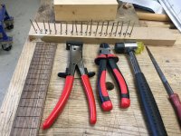
Tools ready.

EFF9A0AF-6958-46B6-8C31-189C61014E08_1_201_a.jpeg

Cat all the fretsover length ready to have the tangs trimmed.

B092D0D5-AAC4-442B-A273-D9FB87F2706B.jpeg

If you've seen a previous video, the fret slots are stopped, so you won't see the fret tang ends on the edge of the fretboard. I think that's a neater look.

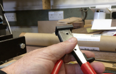
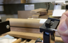
To fit the fret in the stopped slot, some of the tang has to be cut off and I have a special little tool to do that. It guillotines the tang.

Screenshot 2022-09-23 at 18.42.24.png

Screenshot 2022-09-23 at 18.42.47.png

Do both ends so that it will fit in the stopped slot.

B3983C60-2572-45BA-8778-4B130AB7D0F9.jpeg

'Ease' the fret down into the slot.

BC6562ED-5854-4A36-80C0-6715417DEA50.jpeg

Snip the ends of with wire cutters with their backs ground flat.

76D1318A-E830-4E6B-9467-AC1C58998558.jpeg

Halfway and stop for tea.

43192783-CF3B-488E-8E9D-2C59C3EE341E.jpeg
 
Back
Top