• Hi all and welcome to TheWoodHaven2 brought into the 21st Century, kicking and screaming! We all have Alasdair to thank for the vast bulk of the heavy lifting to get us here, no more so than me because he's taken away a huge burden of responsibility from my shoulders and brought us to this new shiny home, with all your previous content (hopefully) still intact! Please peruse and feed back. There is still plenty to do, like changing the colour scheme, adding the banner graphic, tweaking the odd setting here and there so I have added a new thread in the 'Technical Issues, Bugs and Feature Requests' forum for you to add any issues you find, any missing settings or just anything you'd like to see added/removed from the feature set that Xenforo offers. We will get to everything over the coming weeks so please be patient, but add anything at all to the thread I mention above and we promise to get to them over the next few days/weeks/months. In the meantime, please enjoy!

Using Festool KD fittings - landing cupboard

RogerS

Moderator
Staff member
Joined
Jul 21, 2014
Messages
15,492
Reaction score
1,223
Location
Somerset
Folk may recall back in July I posed the question in this thread about the best way of providing storage space here yet allowing access to all the plumbing.
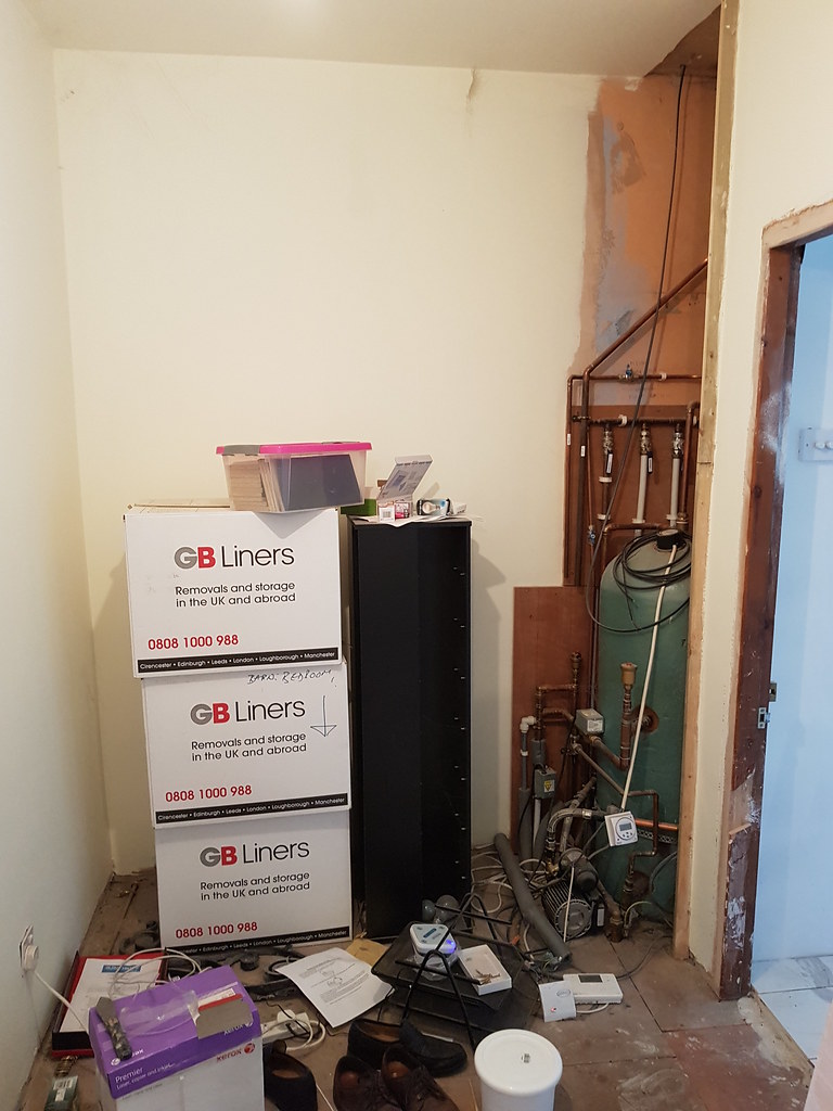


After much deliberation, I came to the conclusion that :-

  • (A) I needed quick and easy access to Mission Control and/or all the isolating valves feeding the plumbing in the house and

    (B) the ability to remove the cupboard without too much hassle if the need arose to do any remedial work to the plumbing in the future (new HW tank, for example).
(A) is easy enough to achieve...it's called a door :lol: .. but (B) is more problematic. MattS reminded me about the Festool KD (Knockdown) fittings and I came to the conclusion that this would solve (B).

This is that story.

Festool provide a different type of connector system to suit each size Domino machine. The larger DOMINO XL DF 700 jointer uses this kit at £210
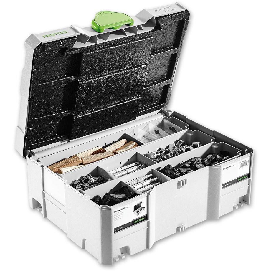

The smaller DOMINO DF500 Q-PLUS jointer uses this kit at an eye-watering £315


However on closer inspection I realised that those kits contained a lot of stuff that I probably wouldn't use and that I could just buy boxes of the parts I needed at a reduced cost. The smaller kit needs a special drilling jig - pricey - but the larger kit needs a 14mm cutter (which I already had). Decision made and so for slightly over £100 I bought four boxes of connectors.

The minimum that you need to make a connection is a :

split-anchor (or expansion bolt as some sites call them).


anchor bolt


The anchor bolt comes in three parts..the actual bolt itself plus two black plastic halves that click over the bolt at the appropriate time - of which more anon.

cross-anchor


In the Festool coding, the key letters are after the hyphen. eg. SV-AB D14/32. The D14 refers to the size cutter (in the kit for the larger Domino there is just the one size 14mm) and the 32 refers to how many in each box.

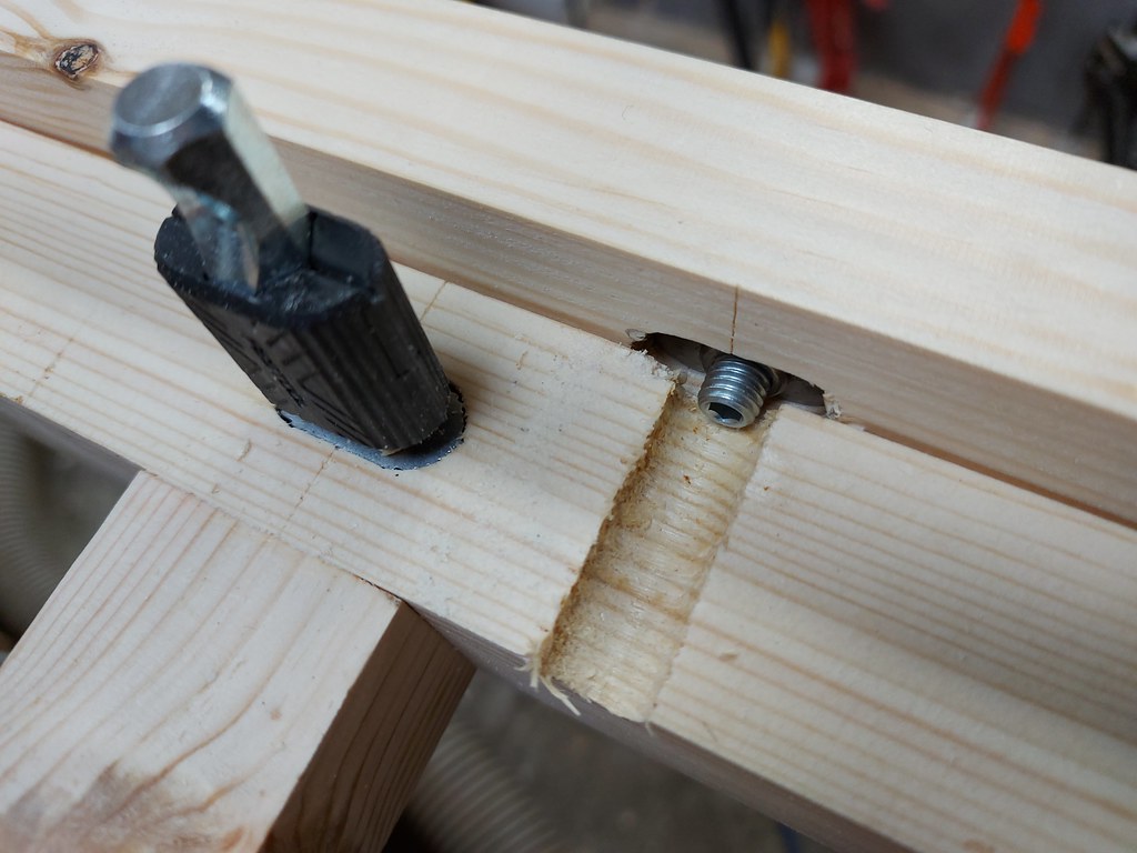
The way the connector works is that, after drilling the appropriate slot, the split-anchor is inserted and then the anchor bolt slowly screwed into it forcing those serrated jaws apart and into the wood on either side of the slot.


The anchor is then covered with the two black plastic halves.
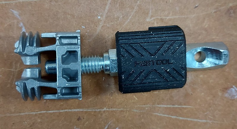

(Obviously that anchor bolt in the photo hasn’t actually been screwed in all the way!).

Then in the piece of timber you want to join together, another slot is cut at 90 degrees to the other one and the cross-anchor inserted.


That’s the theory. How well does it work in practice ?

First off, you really have to keep your wits about you when cutting the slots. Remembering which side you’re cutting from and the settings required on the Domino machine is crucial. Fortunately Festool provide a drawing with the various settings needed although TBH, as mentioned in another thread I found their pictures not that obvious.


To be continued
 
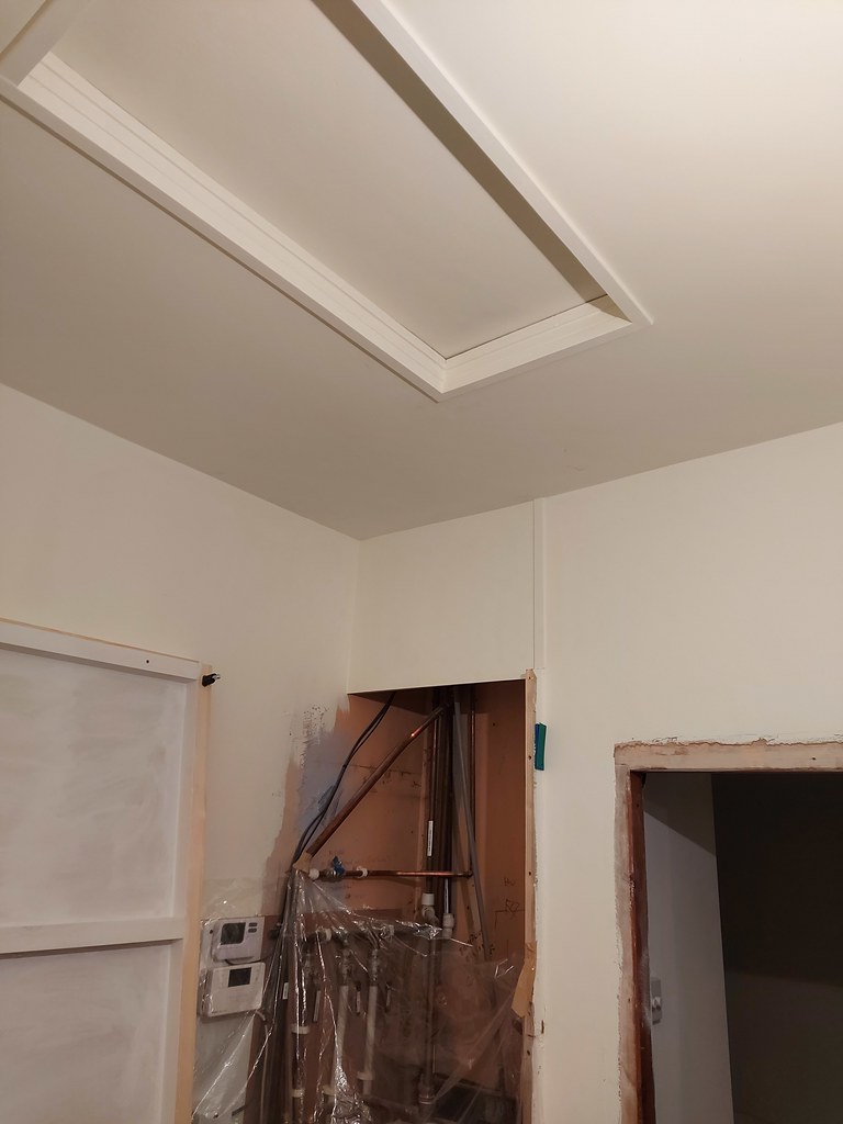
First I needed to tidy up Mission Control from this ..


to this


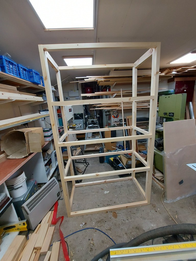
For the cupboard, the plan is four separate sides with shelf supports - glued and Domino’d. These four sides would then be KD’d. When fixed together, you’ve got this carcass.


Then to the front of the carcass would be fixed the KD face-frame - off of which would hang the two doors.

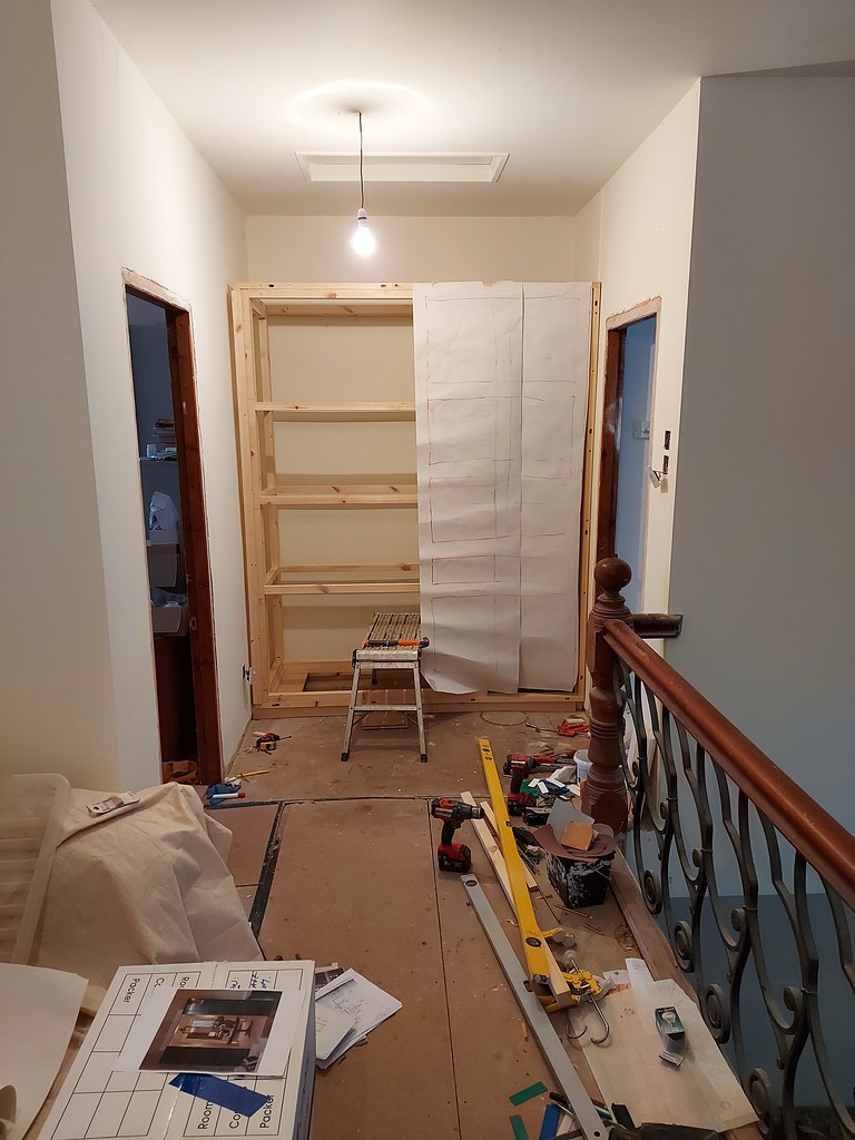
I had a spare sheet of 8x4 18mm ply which I could use for the shelves and so that set the width and depth of the cupboard. The height was determined by hanging up some lining paper and sketching various ideas. We want it to end up looking like a standalone cupboard rather than something ‘built-in’. Final result …2.1m tall….give or take.

This is Plan ‘A’ and all the while you have to be planning ahead and thinking ‘Have I got access to the allen keys for fixing the KD joints?’ Next question was whether to glue up the four sides first and then make the slots for the KDs or make the slots first in the stiles before gluing up.

For those of you unfamiliar with the Domino machine, you have the ability to select different widths for the slot that the machine cuts. The normal setting is one that gives you a very tight fit for the Domino. Unless you are extremely careful with your marking out and cutting the slots, if you only use the normal setting then you can end up making a rod for your back as you try and coax the Domino’s into a slot that is, maybe, slightly out by a fraction of a mm. The longer the two lengths of timber and more Domino's there are, the more carefully you need to mark out and make the slots.

So the usual trick is to have one reference slot using the normal setting to align your two pieces of timber, then use the same setting on one piece of timber down the length for the rest of the Domino slots but on the other piece, cut at a wider setting thus giving you a bit of wiggle room when you fit the two pieces together at glue-up.

I decided that I’d glue up the four ‘ladder’ frames first and then align them carefully together and then knife mark them both across where the KD fittings would go.

There is SOME wiggle room with the KD fixings. A standard 14mm Domino is 28.2mm wide. The black snap-on covers on the Anchor Bolt are 27.2mm. The anchor bolt and cross-connector require two slots to be made at 90 degrees and to get them perfectly inline is a big ask. So they planned for that and made the cross-connector 25.6mm wide so a bit of wiggle room there, certainly.

You can also see that there is a sort of countersink in the end of the anchor bolt into which the allen key in the cross-anchor will go as it’s tightened up and so pulling the joint tight. Festool have really thought this through.

Nevertheless I marked up with a knife as carefully as I could and also ensured the Domino machine was spot-on the line, using additional supports to minimise any rocking of the machine as it was plunged.

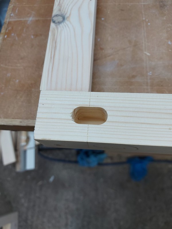
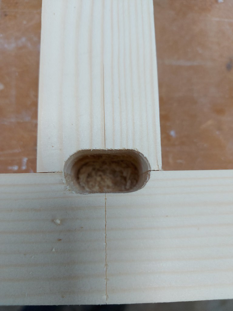
So…first slot (bit embarrassed as I see that the basic frame alignment is out a bit)


Take one split-anchor


And press it into the slot. I use a clamp to ensure it goes in square with a final light hammer tap to make sure it’s flush and square with the surface of the wood.


As you can see, the split anchor is a tight fit.

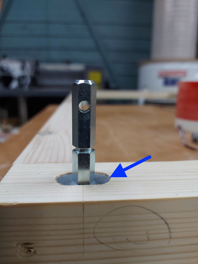
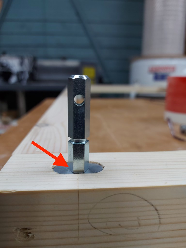
Then we take the anchor bolt and screw it into the split-anchor forcing those serrated jaws apart. You can either use a small spanner or a small hex socket. And it was at this point that I noticed a couple of things that I wasn’t expecting.

In the instructions that come with the anchors,

Festool show at (1) that the spilt-anchor should be flush with the surface (red arrow) and what they don’t say or show is whether or not it should stay flush with the top after the anchor bolt has been screwed in. Because if you look closely here, you will see that as the bolt is tightened the split-anchor is drawn below the surface by about 1mm. I wondered if that would throw the final fitting out of whack.


Then looking at (2) on the diagram, it also suggests that the anchor bolt is not screwed in fully. That also gave me pause for thought because there is a small sleeve on the bolt that is a perfect fit for an indent on the split-anchor. On looking more closely at the Festool drawing, it does indeed go into the indent. Just wish they’d make these things clearer.


You have to remember to rotate the bolt until the countersink is facing the cross-anchor. Once the black clip-ons have been fitted, you can easily turn the bolt by hand to adjust.

In Peter Millards’ YouTube review of the smaller KD fittings (for the Domino D500) he expressed concern about the vulnerability of those anchor bolts. In the case of the larger fittings that I’m using (a) they are much more substantial and (b) can easily be undone by hand leaving the split-anchor securely behind.

Here’s one joint prior to final tightening.


Having cut some of the slots I discovered that the CUF (cock-up fairy) had visited and I’d cleverly put a slot bang through the joint on one of the shelf supports.


One of the advantages of this system is that if you do put a slot in the wrong place then you simply glue in a spare Domino into the errant slot, leave to dry, cut flush and redo the slot in the right place. DAMHIKT. However, here I felt a judicious extra support was best.


I can’t tell you the sheer relief when I offered up the two frames to find that they simply dropped into place. And this is where we came in….


....to be continued
 
I don't know where you are in the UK, but if it weren't too far you could have borrowed my Zeta, it seems much faster and easier than the kd fittings
 
csalisbury":a82yrhbq said:
I don't know where you are in the UK, but if it weren't too far you could have borrowed my Zeta, it seems much faster and easier than the kd fittings

That's very kind of you but you're 6 hours and 300 miles away !
 
Thats a hard no then :) so do you see shortcomings in these connectors?

The only thing i could imagine would be bigger sizes in sheet good as there wouldn't be much meat left, but other than that, festool don't seem to make too many glaring design mistakes in their products
 
csalisbury":2a2keygo said:
....
The only thing i could imagine would be bigger sizes in sheet good as there wouldn't be much meat left,.

That's where the smaller connector would come in. I've got that in mind for another project possibly here

Regarding your earlier comment re the Zeta being faster, I'd still have had a learning curve to go through with that. Also it was a lengthy post as I took the time to explain my thinking etc for anyone not familiar with the Domino. That possible makes it seem slower !
 
ill see if i can post a private video on YT today showing how the zeta is (although i think there are a number out there already).....but be warned i'm face/body for radio with zero production value :text-lol:
 
RogerS":21u1b8os said:
50596487121_83fc5cbf69_b.jpg
[/url]
....to be continued
Interesting Rog, I can see where you're going with it now. I would have done all that using a combination of pocket hole joinery (ideal for this sort of application) and/or dowels - Rob
 
Woodbloke":2i9uq6zg said:
RogerS":2i9uq6zg said:
50596487121_83fc5cbf69_b.jpg
[/url]
....to be continued
Interesting Rog, I can see where you're going with it now. I would have done all that using a combination of pocket hole joinery (ideal for this sort of application) and/or dowels - Rob

No, they wouldn't have worked at all, Rob. Since making the basic carcass, I must have disassembled/re-assembled it 6 or 7 times. Very quick. Very easy. Very clean. Non-destructive. Pocket hole screws ...you'd have stripped the wood with the threads by now.
 
Offering up a trial fit to see what it looks like in situ. All good. I have enough room down the RH side to get to everything thus meeting objective (A) and that it can be dismantled meets (B).


Next we need to work out how the face frame is going to fix onto it. Something’s missing. I need a sub-frame that fits to the carcass and then flies over to the RH side. I’d previously planned ahead (rare event, I know) and already had fixed a vertical riser tied back to the wall. You can see it - RH side going all the way to the ceiling. That needs trimming down in height. Plus that gaping hole in the plasterboard above the HW cylinder needs filling. While I’m there I might as well finish off the surround to the loft hatch (yup..I checked…can still use it! It’s been like that for 45 years.) and as the decorating bits and bobs will be out, fiddle about with some niggling issues left behind by the builders.

There’s a frame behind there. I even made some joints (half-laps).


Digression over. Back to the interesting parts.

What we need is a sub-frame fixed to the carcass that will span the entire width that the face frame + two doors will be fixed to. I have to have this extra piece because there is no easy way for me to get a KD fitting onto the carcass to take the face frame particularly as the carcass doesn’t span the entire width

I can take advantage of this separate piece of construction by offsetting relative to the carcass and so give the doors a few mm behind them so that there is no likelihood. of them binding against the carcass when shut. The sub-frame is fixed to the carcass with Domino’s naturally.

If I make it wider than the carcass then I can also offset the whole cupboard forward over a plinth fitted underneath to match the sloping floor which will look better aesthetically. You can ignore the lack of a decent scribe along the bottom piece of the sub-frame. Oak floorboards will be concealing it.


Part of the sub-frame already prepared with the KD fixings for the face frame.


I debated trying to make the face frame as a single unit but came to the conclusion that four parts was better. The joins can be lightly filled and will be painted anyway.


Side panels with hardboard backs awaiting the decorator. An eagle eye will spy two ‘mistakes’ in the rear one with Domino ‘correction’ pieces.

The other design niggle is the fact that the carcass needed some grooves cut into it for me to get the allen key in for fitting the face frame.


So we’re now up-to-date. SWMBO is painting it while I’m making the doors. Design on this scrappy piece of lining paper (ignore that centre stile) !

 
MattS":335xkeiu said:
I've never used the connectors myself, should have guessed being Festool there would be a big set up cost!

Actually for the £100, the flexibility and future-proofing it gives me is well worth it IMO.
 
Bravo, Sir Roger of Haltwhistle! That is a one great story and a satifyingly elegant install. Must be very satisfying to get to.this stage and 'flip the bird' at the C.U.F..

Sam
 
Finally found some time to work on the doors. I'd found that a few of the internal doors that I've made have had the stile on the opening side bend badly which is a tad annoying. I'd thought that I'd done everything right, thicknessing equally off each side but clearly not the solution.

Picking up on Mike G's point re his doors-to-be, heat and the Warp Fairy I decided to try a different approach. The stiles need to be 90mm x 30mm finished size. Ideally I'd have had some 4" x 1.5" boards in stock but not to be. AlI I had was 4" x 2". Crown cut which doesn't help. Must ask my timber merchant next time if they have any quarter-sawn.

As an experiment, one still is going to be done the traditional way - plane one side of the face, then square up the edge then run it through the thicknesser. I left the 4 x 2 in the house for a fortnight then I took it down to 40mm - equally off both faces - and brought it back into the house. The next morning gazed upon the banana. Not bad enough to justify another go since I can make it the hinge stile...four hinges..will keep in straight and tell it who is boss.

For the second experiment, I planed the next 4 x 2 on one face and then thicknessed lightly the other face. I then ripped it down the middle, flipped the two pieces over so that the planed faces were on the inside, applied a liberal coating of glue and clamped the two halves back together again. My theory being that doing it this way, any attempt at movement should be equal and opposite thus cancelling out. Resulting in no movement and a straight stile. To give the theory a thorough test, I didn't bother acclimatising the 4 x 2 prior to doing the machining first either. The next morning, into the workshop to see a perfectly straight piece of timber. Result ! Over the next few days I thickenessed it down to the 30mm and even took it in and out of the house. It remained straight.

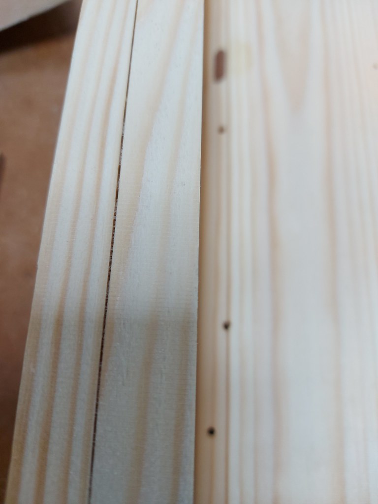
Happy with the experiment, I then started in the remaining two stiles and this is when the C. U. F. showed her hand. I didn't realise it but as soon as I ripped each stile, they started to cup slightly and I didn't pick this up until during the glue-up. A bit annoying and if I had separates rather than the combi I'd have knocked up another couple of stiles and planed off the freshly cut faces after ripping. Instead I clamped and screwed all the way down in an attempt to tame the cupping. It was partially successful but in some areas slight gapping occurred. About 0.25mm


The actual joint seemed solid enough but just to belt and brace things, I ran some domino's through and glued them in place. I know...I know...it would have been easier and quicker to knock up a couple more stiles. :oops:

They'll be filled and sanded prior to painting so that end-grain of the domino won't be seen.


Not much else to say TBH. The stiles were scribed on the spindle moulder with painstaking accuracy. Then everything that needed it, moulded. I used my marking knife this time rather than a pencil this time. :oops: Accuracy went up several thousand percent.

Hinge rebates routed out prior to assembly.


Then I had a :idea: brainwave. Since these doors are going to be large and awkward, I actually fitted the hinge stiles so that the screwholes would be done and dusted thus making hanging the finished door a doddle. And so it turned out to be. Dunno why I'd never thought of doing that before. :eusa-think:


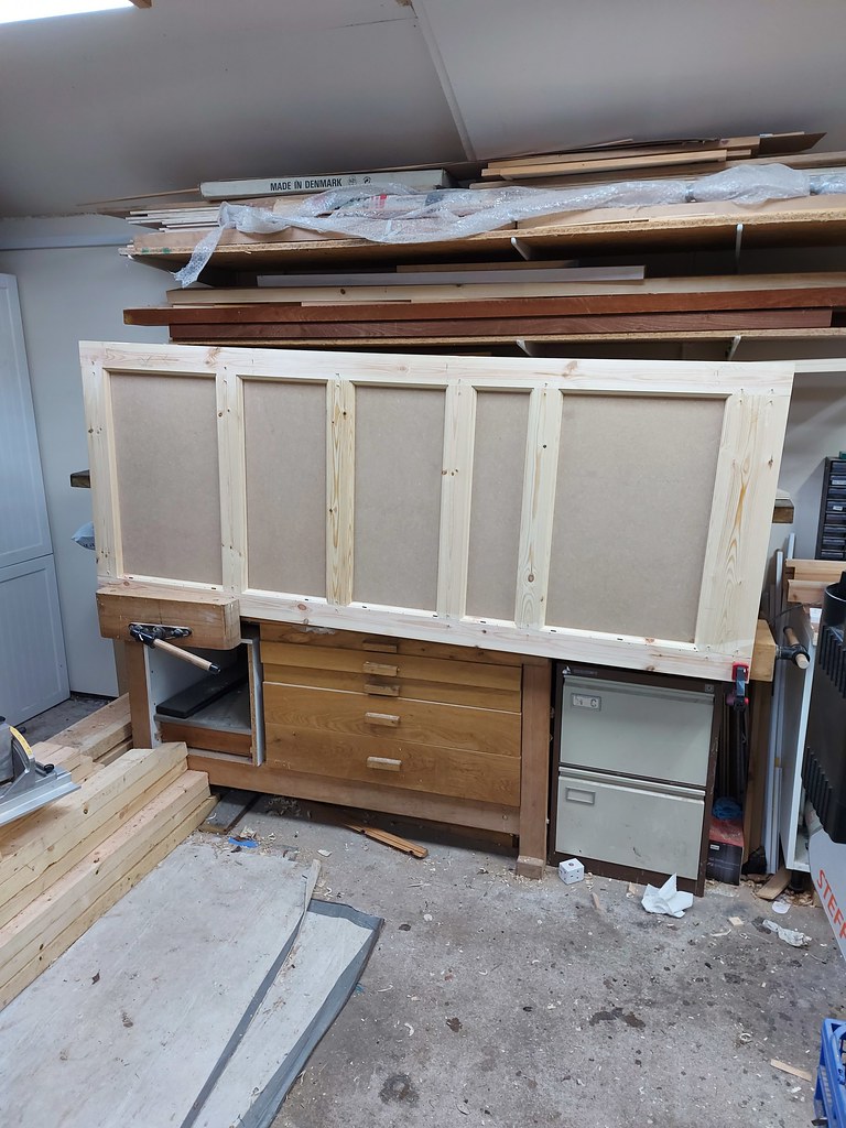
Floating panels. Glued up and clamped and Tongue-Tite screws temporarily run through the dominos


because this time, rather than making it all square and in wind on my assembly bench, highly likely that the actual cupboard carcass - given the size- might be slightly out of wind (although I have installed a Cunning Plan to cope with that should the need arise)


And hung.


So when the country gets back to work again and I can get another sheet of 6mm MDF, I'll do the other door.
 
Yep, there's a very good reason that up market bespoke windows and doors feature laminated timbers rather than solid. Nice experiment, Roger, and a useful lesson for anyone who uses pine for doors, particularly in challenging environments.
 
Looking good Rog.

You are lucky getting decent pine not the crap we have available.

Mike G":bt7e4hx4 said:
and a useful lesson for anyone who uses pine for doors, particularly in challenging environments.

:text-+1:
 
I mentioned in passing that I had installed a Cunning Plan to tweak any wind once the doors were fully fitted.

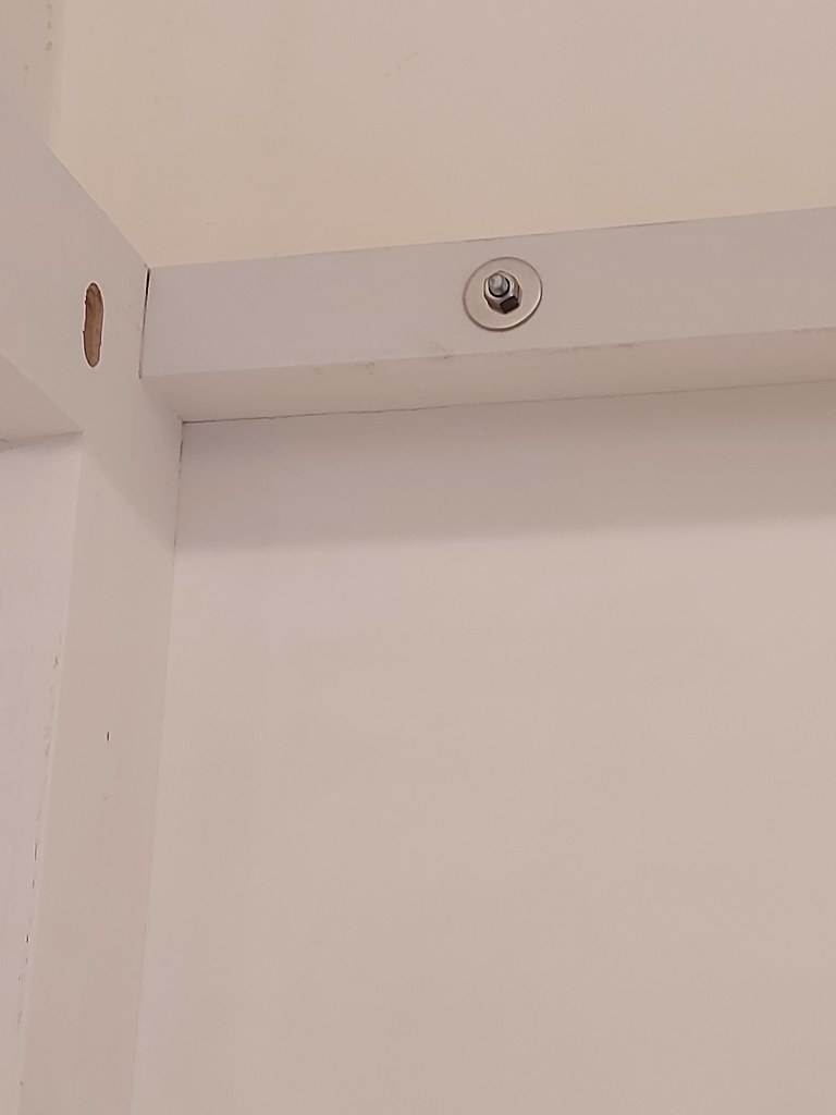
Behind the cupboard and at the top is a bearer screwed to the studs in the wall. A couple of those threaded inserts then screwed into the bearer to line up with the top rail of the rear panel of the cupboard. Screwed into those inserts is a 6mm threaded stud that pokes through the top stile.

Nuts and washers either side allow me to adjust the top of the cupboard to 'skew' the carcass if necessary.


Back
Top