• Hi all and welcome to TheWoodHaven2 brought into the 21st Century, kicking and screaming! We all have Alasdair to thank for the vast bulk of the heavy lifting to get us here, no more so than me because he's taken away a huge burden of responsibility from my shoulders and brought us to this new shiny home, with all your previous content (hopefully) still intact! Please peruse and feed back. There is still plenty to do, like changing the colour scheme, adding the banner graphic, tweaking the odd setting here and there so I have added a new thread in the 'Technical Issues, Bugs and Feature Requests' forum for you to add any issues you find, any missing settings or just anything you'd like to see added/removed from the feature set that Xenforo offers. We will get to everything over the coming weeks so please be patient, but add anything at all to the thread I mention above and we promise to get to them over the next few days/weeks/months. In the meantime, please enjoy!

CNC Router! (Drawing Ukulele Components)

Robert":1x7xplrd said:
Malc2098":1x7xplrd said:
The safety circuit I'm trying to achieve here, is to cut the power to the VFD and hence the spindle (230v), but leave power to the controller (24vDC), so that I can reset the job.

Can you explain that a bit more please.

How does stopping the spindle help anything? If the axes are still moving a stopped cutter will do nearly as much damage to the workpiece as a moving one. Don't you need an emergency pause button?

On the metal punching CNC that meant pressing the single step button. Then you'd have to press start for every line of gcode to progress and could sort out a bent edge or whatever at leisure. E stop was for when the sheet of metal got screwed up and the program abandoned.

Robert, I'll try. I don't think I can just have a NVR switch on the incoming power, because that would also kill the supply to the 230AC to 24DC converter supplying the controller and steppers. I need the controller to stay powered, so I can hold it in pause mode and I think so I can move the XY&Z axes while the spindle, capable of and quite often it seems runs at 24,000 rpm, needs to be shut down and stay shut down, especially after a power outage and return.

You clearly know and understand everything about your setup, but I only started learning this just before Christmas, so I am taking baby steps and willingly accept any educated advice going, but even that sometimes conflicts with others. And as the hardware and open source software is relatively new, I'm treading very carefully and slowly, and probably spending more hours reading than wiring.

Dave, it's the xPro V5. https://www.spark-concepts.com/cnc-xpro-v5/
 
My last contact with CNC anything was 16 years ago now. We had pre built monster machines weighing 10 tons each and punching 300 holes a minute.

I've got a lot to learn before I consider joining you on this adventure. DIY machines and all that goes with it is completely different to programming and operating branded machinery.

Our first machine I wrote the gcode myself on a pad then typed it into the controller - it then saved to cassette tape!. Then we got PC software that would check the code before you ran it and show you on screen. After that came software that could read a DXF file and let you place tooling against features. That system improved over the years so I've forgotten most of the gcode commands as i stopped having to know them. None of that helps with a home built machine beyond have a grasp on the principles.

Stupid question - you have a stop button - is there a physical cycle start button...single step button etc that I remember or is it all software initiated - click go on a PC screen or similar?
 
Robert":33io08q3 said:
Stupid question - you have a stop button - is there a physical cycle start button...single step button etc that I remember or is it all software initiated - click go on a PC screen or similar?

The coded software is passed to the controller via either a usb cable or wifi and onto a micro SD card in the controller. The laptop, connected via either of the above has a graphical interface for the machine, including a graphical eStop. I want the machine to also have an eStop, an off button and an on button, and from what I've researched, this last two go via the contactor. I haven't yet worked out a full diagram for my machine, but I will eventually and won't wire it up until it's passed by my electrician.

I'm certain graphical interface will allow a line by line execution of the gcode if you want.
 
check in the controller manual before you go to much further on the spindle stop Malcolm. A lot of modern controllers have a restart after power loss. unlike the good old days, the code is stored in eeprom rather than RAM, so it remembers it's last known position. It also normally starts back up in manual override to so you can jog through the code and check it's position before it starts again. I swear that black magic is at work to do this. :lol:
 
novocaine":blez7xhf said:
check in the controller manual before you go to much further on the spindle stop Malcolm. A lot of modern controllers have a restart after power loss. unlike the good old days, the code is stored in eeprom rather than RAM, so it remembers it's last known position. It also normally starts back up in manual override to so you can jog through the code and check it's position before it starts again. I swear that black magic is at work to do this. :lol:

Thanks, Dave. The author of the controller documentation assumes a level of knowledge different from mine. :) However, I will use it and by taking baby steps, I will get there.

For you who have similar knowledge, here is that documentation.

https://github.com/Spark-Concepts/xPro-V5/wiki
 
Interesting read at that link Malc. Only skim read some of it so far but I'll go back for more.

Some learning curve :)

Glad I can just watch at the moment!
 
Just while I wait for approval of my wiring diagram and waiting for electric parts, I thought I'd start building the frame.

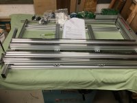
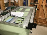
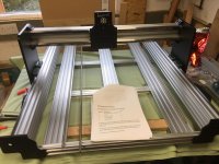
First the spoilboard support frame. It's upside down in the photo, but that's the best way to construct it. All the parts, screws, T nuts, brackets etc., are all in separate labelled bags.

IMG_6436.JPG

I think it will fit just right on the tablesaw.
 
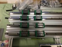
Today I fitted the linear bearing rails to the Y axis beams. Had to clean a little transit oil off the rails ready to take the bearings.

EF8AE8E7-81C3-4DA4-9339-099A1651A93C.jpeg

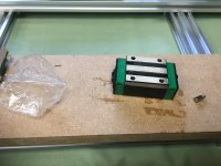
The online wisdom is to clean the transit grease out of the linear bearings with Meths and then regrease with lithium grease. That'll be the next job while I wait for the grease to arrive, although I could attach the bearing rails to the X and Z axis beams tomorrow.

I've also soldered the wires to the 4 pin connecter for the spindle ensuring that the green wire was soldered to pin 4 which, when connected, is earthed to the body of the spindle.
 
I watched a couple of youtube videos of people building this brand CNC this morning. Not the full build just partial. Reviews were generally pretty good. One commented the mechanical parts had good accuracy. Also said the mechanical instructions were very good and the electrical ones not so clear to follow.

Keep posting :)
 
Robert":3b5jllnw said:
I watched a couple of youtube videos of people building this brand CNC this morning. Not the full build just partial. Reviews were generally pretty good. One commented the mechanical parts had good accuracy. Also said the mechanical instructions were very good and the electrical ones not so clear to follow.

Keep posting :)

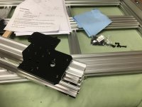
As you can see, Robert, I've got the framework instructions in front of me and ticking off each part as I go.

They're right about the electrical and programming instructions; they assume a prior knowledge, of which I am lacking, and have had to research.

There's several YT videos series available to see how to construct, wire and program this machine. They all seem to know what they're doing. I don't. :D So I won't make a video series, but for us on here, I might video short pieces where movement is not obvious in a photo.
 
Malc,
I'm sure somewhere there will be an enthusiasts forum for this machine and just like here, there will people who tend to be helpful and their names will keep popping up and equally there will be sources of random noise.
I tend to lurk for a while and work out the helpful guys and how to drive the search function.
Research your queries and then post questions to clarify your uncertainties and see what the helpful guys say.

Watching with great interest.

Bob
 
9fingers":1adarqji said:
Malc,
I'm sure somewhere there will be an enthusiasts forum for this machine and just like here, there will people who tend to be helpful and their names will keep popping up and equally there will be sources of random noise.
I tend to lurk for a while and work out the helpful guys and how to drive the search function.
Research your queries and then post questions to clarify your uncertainties and see what the helpful guys say.

Watching with great interest.

Bob
OK, Bob. I have another source, but let's try here, too.

Can you see any issues with this?
Power Wiring V4.png

It's still a work in Progress; I forgot to move the earthing block and there's a communication wire between the controller and the VFD, which is new in the development in these electronics.

And, would there be any need for the additional E Stop if the primary E Stop causes the signal to be sent to the VFD to power down the spindle?
 
A couple things come to mind.
I not routinely be stopping and starting the spindle with the contactor. Far better to use the low level inverter controls. you may already have this in hand as this is only the power diagram.
There are multiple levels of Estop/stopping you might want to consider.

Incoming power loss NVR where you will possibly lose all settings such as current position XYZ and starting datum unless you have some sort of UPS to retain these.

End of the days work. Possibly similar to above but maybe the computer is still up to retain data for restarting the job the next day

The oh sh1t situation where you can see a forthcoming snarl up and want to tweak something but retain everything for a clean restart.

A second oh sh1t case when it has done something wrong and wrecked the job which is arguably similar to the first case.

How you want to handle these and indeed what the controller software already has "in mind" would be the areas for investigation. 2 and 3 will obviously need the power left on unless you programme in a safe parking place with safe trajectories to near extremes of XYZ values from which you can restart.

I say this from hopefully a logic engineering approach but zero experience of CNC. However I'd expect these fundamentals to have been thought about by the designers and being inbuilt in the system design.

Bob
 
Thanks for the advice, Bob.

I'll be switching the VFD on and off by means of its own isolation switch shown in the diagram after the circuit has be made live via the contacter. The spindle can be manually controlled from the keyboard of the VFD or from the Controller Interface. I've no intention of switching off routinely from the action of the connector stop/start switches.

I will develop a routine for switching the machine on and off at the start and finish of a day's work.

There are various YT vids of how to set up 'home' and 'zero' locations and to lift the Z axis first to avoid any obstructions. Likewise there are macros to park the spindle in a convenient place for tool changing, and to continue with the next tool path.

I am hoping both the osh1t situations you describe will be covered by the estop button connected to the Controller, but the contacter stop can be a backstop in extreme emergency, which should cut power to the VFD and the Spindle, while leaving the controller powered.
 
Time to prepare the bearings.

4D315203-4835-49CF-A2D1-1B3AF8C28DB6.jpeg
Four for each Y axis rail.


F379E41C-6E6C-4533-9DE2-B84085A45AEE.jpeg
Strange looking things when you're used to seeing round ones!

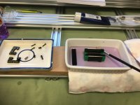
And they're covered in transit lube, but not as gloopy as some YTers have said they've got theirs. perhaps the suppliers have listened to feedback. Anyway, a quick wash in meths.

36F2EB51-B4AB-465E-8631-D7B6D41BAE6D.jpeg


Followed by some special lube.

D11535B4-B2C5-42FF-A5D1-9FBE08425516_1_201_a.jpeg
I gave two gentle presses each end till I could see the lube exit by the closest balls.

4207A8EE-70F0-4BA1-8042-44954736CD81.jpeg
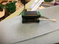
Then gently pulled the balls round with a cotton bud till all the balls had passed through the lube. There are four oblong races in each bearing.

ABF0C4DC-52ED-408E-AC28-5DBD62F978AC.jpeg
All eight bearings done and fitted to their rails.


124D8F39-B819-4A72-A6D4-1F5D8D11B3B3.jpeg
Time to fit the Y axis rail end plates.

573C6C78-EC25-4DC2-8F8F-2BDA97E951AD.jpeg
After both end plates fitted, time to fit the first Y axis rail to the spoil board support frame.


At this point I have decided to leave the bearing rails loose on the beams because even with 17 T nuts fitted in each beam and screwed through the rails, before tightening there is noticeable play. So before I fit the X axis plate to the bearings I need to ensure that both rails are not only parallel, but also the correct distance apart. Job for tomorrow, after I've fitted the plates to the other Y axis beam.
 
The more metal I start fixing to it, the heavier it gets! I'm going to have to work out a way to remove it when I need the table saw. Probably a joist hoist to raise it to the tie beams.

Anyway I fitted the Y axis plates.

EA7BBEF9-2BA2-4F44-B361-182592D67A11.jpeg

Then I fitted the first lead screw and its bearings, round ones this time, and then tested the transport with a cordless drill.

[youtubessl]0aTwYMuQQgw[/youtubessl]

https://youtu.be/0aTwYMuQQgw

Then I fitted the second lead screw to the other Y axis beam. One of them is noticeably less free than the other. I've narrowed it down to the plastic nut block and am online seeking advice from other owners.

So then I fitted the X axis bearing rails and bearings to the X axis beam.

C9FBC661-7058-4401-9523-46FC632086E6.jpeg

That was it for today.
 
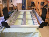
The X gantry is fitted.

3F81F30F-45E7-4921-9699-1275C7985984.jpeg


I've removed the Y axis lead screws for now. The online advice was to use PTFE spray for lubrication between the metal lead screws and the plastic nut blocks. Then I read through the instructions again and watched a couple more videos and realised I was getting ahead of myself. The leadscrews cannot be tensioned until the stepper motors are fitted. So, I'll fit the X and Z screws first and then go back to the Ys.
 
Does the manual give a total weight for the machine? Couldn't see any mention of weight on Ali ex.
Obviously would have to add the weight of the MDF panel.
 
Robert":xxe4oxyn said:
Does the manual give a total weight for the machine? Couldn't see any mention of weight on Ali ex.
Obviously would have to add the weight of the MDF panel.


I've just taken the packing to the tip. I'm sure I saw 75kg on it.
 
75kg ! and you are going to hoist it up and out of the way when not in use. :o . That seems like a very
sensitive piece of equipment that wont take kindly to being knocked.
 
Malcom I saw an electric engine hoist in Lidl last year or maybe the year before lost track :D maybe on a base with some locking pins when lifted.
Nice work BTW.
 
I shall do some proper weighing when the build is complete. Then I'll be able to determine it's best method of moving around the workshop. Currently it fits nicely on the table saw, and because that's on heavy duty casters, I can move it around to get all the way round the machine. But, I can only see it going upwards when I need the table saw.

Got some more done.

383FD9FB-8486-4817-82A8-EB6BB2DC7D5E.jpeg

D1DCF361-8951-43A7-9D2B-D29E81EEB91C.jpeg

Although it's not easy to see in the photo, the first stepper motor is fixed to the Z axis.
 
Well basically that's the framework/chassis finished with the leadscrews and stepper motors fitted.

Drag chains and wiring next.

6DF9DD6B-B23A-4E6C-B4E2-EB766636259D.jpeg
 
All wired up.

Now I've got to test continuity of all that wiring and then start connecting it to the controller and VFD.

I think I'll just connect to the controller first and see if they'll move around. :)


D75AB1DE-A9FC-4EBB-94AD-BCFDE40765F4.jpeg
 
Well that wasn't a good start.

The documentation is written in techspeak! I only did Latin, French German and Russian!

F049BB22-C06B-4D2E-9318-C8B5C07A438A.jpeg

[youtubessl]DuZuAcRRrAo[/youtubessl]

https://youtu.be/DuZuAcRRrAo

That noise is EMI, I think it's called, coming from the stepper motors, which weren't moving. In fact nothing moved.

Whenever it will work, I think it will be good. What you see on the screen is the wifi connection between the laptop and the controller. I even got that on my phone, too, so I could control it from there….when it works.
 
Watching with interest :)

If it is any help CNC punching machines had to be 'homed' before they could do anything. Guess yours needs that to get started.
 
I am not sure it should make that noise.
On my home made CNC I used a grbl controller based on an Arduino and it was quite at rest.
 
Thanks, Gents.

Robert, in theory, that should be how you start a job by homing, but I can't yet get the motors to move.

Dave, I've used two different grbl controllers, including the one in the controller firmware, but still now proper control.

I'm reaching out to cyberspace. Might have had some replied overnight.
 
Silly question but there isn't a mechanical lock/carriage protection gizmo inside the motors that has to be removed?
 
RogerS":1t5lezcz said:
Silly question but there isn't a mechanical lock/carriage protection gizmo inside the motors that has to be removed?

Not to my knowledge, Roger. You have to spin the spindle with your fingers while you're trying to find the coil pairs when first wiring.
 
OK...worth a try. I know little about these motors but wondering if perhaps you had a couple of windings that were accidentally wired to oppose each other....might account for the sound you hear.
 
RogerS":1ikww83s said:
OK...worth a try. I know little about these motors but wondering if perhaps you had a couple of windings that were accidentally wired to oppose each other....might account for the sound you hear.


Thanks. Speaking with Australia (!) at the moment and need to 'flash' the firmware with a bit of software to stop the screaming.

After lunch.
 
I've flashed my firmware!! :D

(Used to nick people for that in the 70s!!)
 
Back
Top