

-
Hi all and welcome to TheWoodHaven2 brought into the 21st Century, kicking and screaming! We all have Alasdair to thank for the vast bulk of the heavy lifting to get us here, no more so than me because he's taken away a huge burden of responsibility from my shoulders and brought us to this new shiny home, with all your previous content (hopefully) still intact! Please peruse and feed back. There is still plenty to do, like changing the colour scheme, adding the banner graphic, tweaking the odd setting here and there so I have added a new thread in the 'Technical Issues, Bugs and Feature Requests' forum for you to add any issues you find, any missing settings or just anything you'd like to see added/removed from the feature set that Xenforo offers. We will get to everything over the coming weeks so please be patient, but add anything at all to the thread I mention above and we promise to get to them over the next few days/weeks/months. In the meantime, please enjoy!
You are using an out of date browser. It may not display this or other websites correctly.
You should upgrade or use an alternative browser.
You should upgrade or use an alternative browser.
CNC Router! (Drawing Ukulele Components)
- Thread starter Malc2098
- Start date

DaveL
Old Oak
Well done [emoji2]

Malc2098
Sequoia
DaveL":1wmn8lgd said:Well done [emoji2]
Thanks. Not quite there yet, but getting there.
Malc2098
Sequoia
Mike G":13s4jv2t said:Fun, fun...... It's a whole lot quieter now, thank goodness.
Does the Z axis work?
Yes. I didn't include it in this video, because I set the Y and X axes up for 200mm travel to visually show how they worked. I'd have had to get back into the UI and reduce the travel distance just for the Z axis which would have taken a bit of time and you'd have got bored.

I've now got to set the spindle up.

- Joined
- Jul 21, 2014
- Messages
- 10,414
- Reaction score
- 165
Coming on nicely. Shame the supplier did not advise you about the need to update the firmware
Bob
Bob
Malc2098
Sequoia
9fingers":108sf6s1 said:Coming on nicely. Shame the supplier did not advise you about the need to update the firmware
Bob
Thanks, Bob. the supplier made it quite clear that they were not responsible for the software because of it's open source nature. It provided full warrantee on the hardware. But they do point you towards sources of advice etc for finding out about the software.
And me, I'm a woodworker with a bit of IT knowledge, but not a lot. So some nerdy people might catch on quicker than I have.


Great stuff Malc,
Will it do letter carving?
Will it do letter carving?
Malc2098
Sequoia
RogerS":30uxruny said:bscene-drinkingbuddies:
Now wotcha going to make ? I've got a staircase could be rebuilt
Cheers! Ha!
Malc2098
Sequoia
Andyp":2wbstn71 said:Great stuff Malc,
Will it do letter carving?
Yes….eventually!
NickM
Old Oak
The possibilities are endless!
Malc2098
Sequoia
NickM":1ssczani said:The possibilities are endless!
Absolutely……if the operator learns how to program it properly!


Well done Malc. Must feel good now the easy bit is done
Learning all the software is going to take a while.
To keep this dream alive can you give me some sizes please. Remind me what the working area is for the one you have, then could you give the overall sizes of the machine - length width and height. I would think all models will have the same difference between working area and overall sizes so with your info I can work out how much space would be needed if I went bigger and have a measure up. TIA.
Learning all the software is going to take a while.
To keep this dream alive can you give me some sizes please. Remind me what the working area is for the one you have, then could you give the overall sizes of the machine - length width and height. I would think all models will have the same difference between working area and overall sizes so with your info I can work out how much space would be needed if I went bigger and have a measure up. TIA.
Malc2098
Sequoia
Robert":17db3137 said:Well done Malc. Must feel good now the easy bit is done
Learning all the software is going to take a while.
To keep this dream alive can you give me some sizes please. Remind me what the working area is for the one you have, then could you give the overall sizes of the machine - length width and height. I would think all models will have the same difference between working area and overall sizes so with your info I can work out how much space would be needed if I went bigger and have a measure up. TIA.
Three steps forward, one, or two even, backwards. For some reason the controller isn't liking the controller software and has thrown a hissy fit. I'm talking to a guy Australia who's helping me sort it.
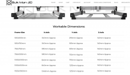
In the meantime, these are the dimensions from the Bulkman (my supplier) website. I bought the 750x1000 because I wanted the length for guitar necks, but also to fit on my tablesaw bed, which you can see in my photos that it does.
Good luck with the problems.
Thanks but I don't see the height from bench to the top of the z axis and is there really nothing projecting past 1000mm x 750mm on yours?
Thanks but I don't see the height from bench to the top of the z axis and is there really nothing projecting past 1000mm x 750mm on yours?
Malc2098
Sequoia
Robert":4ngggol0 said:Good luck with the problems.
Thanks but I don't see the height from bench to the top of the z axis and is there really nothing projecting past 1000mm x 750mm on yours?
Ok. Tomorrow's job!
Malc2098
Sequoia
wallace":1j146aot said:CNC it'll never catch on.
Facts like that are never useless! They make good questions in pub quizzes!Three steps forward yesterday, so hopefully another video today, but I might have to buy a new laptop. This old one is really struggling.
Malc2098
Sequoia
I tested the probing facility today.
I've already 'homed' the machine which is max right X to limit switch, Furthest Y to limit switch and upper X to limit switch. It knows now where it is and has 'Machine Home' - 0.0,0.0,0.0 - as a reference point.
I also set the maximum limits it can travel by manually moving the axes to those limits and recurring them. This way it can't 'crash' at either end of each axis.
So before stating a job, it now needs to know where the job 0.0, 0.0, 0.0, is, both on the drawing and on the machine. If it were to specify on the drawing that it would be the left, nearer, upper corner of the workpiece, the machine would also need to know where that is.
I have a piece of equipment called a probe and the control software contains a probe macro.
Here's how it went. Apologies for the definition, I was on full zoom on my iPhone.
[youtubessl]5aO_kwcfeMI[/youtubessl]
https://youtu.be/5aO_kwcfeMI
I've already 'homed' the machine which is max right X to limit switch, Furthest Y to limit switch and upper X to limit switch. It knows now where it is and has 'Machine Home' - 0.0,0.0,0.0 - as a reference point.
I also set the maximum limits it can travel by manually moving the axes to those limits and recurring them. This way it can't 'crash' at either end of each axis.
So before stating a job, it now needs to know where the job 0.0, 0.0, 0.0, is, both on the drawing and on the machine. If it were to specify on the drawing that it would be the left, nearer, upper corner of the workpiece, the machine would also need to know where that is.
I have a piece of equipment called a probe and the control software contains a probe macro.
Here's how it went. Apologies for the definition, I was on full zoom on my iPhone.
[youtubessl]5aO_kwcfeMI[/youtubessl]
https://youtu.be/5aO_kwcfeMI
- Joined
- Jul 21, 2014
- Messages
- 10,414
- Reaction score
- 165
Looks good. With the knowledge of the machine origin (0,0,0) and the co-ordinates of a datum point on the workpiece, you should always be able to recover from a power failure even if the program has machined away the datum.
My 1970s technology DRO on the milling machine has datum points on the glass scales which I can move to, jot down the co-ordinates and similarly recover from power loss. I must admit I rarely use it as we rarely get power cuts but one day I'll regret not using it!
Bob
My 1970s technology DRO on the milling machine has datum points on the glass scales which I can move to, jot down the co-ordinates and similarly recover from power loss. I must admit I rarely use it as we rarely get power cuts but one day I'll regret not using it!
Bob
Good progress. looking forward to the first cut
Malc did answer my question and more by PM if anyone was wondering.
The height of the tallest part on the spindle unit is 550mm. Bits that stick out add 170mm to the nominal width and similarly add 160mm to the length.
So if I was to get a 1500 x 1000 model I'd need enough space for 1170mm wide x 1660mm long x 550mm high - which is quite a lump. I'll see if Malc finds a way move his 70kg machine to use his saw. Bigger would be heavier. Birthday this month but I'll keep procrastinating for now.
Malc did answer my question and more by PM if anyone was wondering.
The height of the tallest part on the spindle unit is 550mm. Bits that stick out add 170mm to the nominal width and similarly add 160mm to the length.
So if I was to get a 1500 x 1000 model I'd need enough space for 1170mm wide x 1660mm long x 550mm high - which is quite a lump. I'll see if Malc finds a way move his 70kg machine to use his saw. Bigger would be heavier. Birthday this month but I'll keep procrastinating for now.
Mslc,
So much of your post read like a foreign language but I enjoyed the vid.
Well done.
So much of your post read like a foreign language but I enjoyed the vid.
Well done.
Malc2098
Sequoia
Now it's time to to configure the VFD to the 1.5Kw spindle. I've checked the wiring and the continuity many times. So here goes.
Well actually, this is Test 2. Test 1 went anti-clockwise! And too much tape flag!
[youtubessl]gX0pNprBrdk[/youtubessl]
https://youtu.be/gX0pNprBrdk
Well actually, this is Test 2. Test 1 went anti-clockwise!
And too much tape flag![youtubessl]gX0pNprBrdk[/youtubessl]
https://youtu.be/gX0pNprBrdk
NickM
Old Oak
Good progress. You’ll soon have it airborne. :shock:
Malc2098
Sequoia
I wouldn't want you to think I'd lost interest, or that you had, but it's one of Mission Control's special round number birthday's this year and she's arranging something for every month. February was a Scotland road trip to see family and friends.
When we got back, stuff had to be done, so there no workshop visits, then, would you believe, the utility company installing poles for fibre on our estate must have damaged my cooper landline while connecting ducting from the pole to the manhole 2 doors away. I say must have, because it went down the same time they were there.
So I contacted my supplier, this was last Thursday, the 24th, and it's been a nightmare with them for a week! I have had to go through not only the security questions etc every time, but I've had to test my own router, my own corded phone and my own BT sockets within the house. This is every time I've had to chase up. Nobody's rung me back.
Nobody's been to look at the manhole. I even contacted the fibre utility because I am interested in a product of theirs. They said they'd send the site project manager to investigate, but I haven't seen him.
So, I haven't been able to download the latest version of the CNC control software. But I've been in the workshop and tried to make progress. As you know I can jog, home and probe the machine. I've connected up the VFD to the spindle and I can manually control that. That's is so much quieter than a handheld router. I can jog and home with the spindle running manually with no apparent EMI problems, but I can get the controller to communicate with the VFD.
But I'm working on it. Rant over, but don't ring my landline. It'll sound like I'm not answering. My desktop is connecting to the outside world via my mobile, at least my supplier has given me unlimited data FOC for 30 days. They'd better fix it before then!
When we got back, stuff had to be done, so there no workshop visits, then, would you believe, the utility company installing poles for fibre on our estate must have damaged my cooper landline while connecting ducting from the pole to the manhole 2 doors away. I say must have, because it went down the same time they were there.
So I contacted my supplier, this was last Thursday, the 24th, and it's been a nightmare with them for a week! I have had to go through not only the security questions etc every time, but I've had to test my own router, my own corded phone and my own BT sockets within the house. This is every time I've had to chase up. Nobody's rung me back.
Nobody's been to look at the manhole. I even contacted the fibre utility because I am interested in a product of theirs. They said they'd send the site project manager to investigate, but I haven't seen him.
So, I haven't been able to download the latest version of the CNC control software. But I've been in the workshop and tried to make progress. As you know I can jog, home and probe the machine. I've connected up the VFD to the spindle and I can manually control that. That's is so much quieter than a handheld router. I can jog and home with the spindle running manually with no apparent EMI problems, but I can get the controller to communicate with the VFD.
But I'm working on it. Rant over, but don't ring my landline. It'll sound like I'm not answering. My desktop is connecting to the outside world via my mobile, at least my supplier has given me unlimited data FOC for 30 days. They'd better fix it before then!
- Joined
- Jul 21, 2014
- Messages
- 10,414
- Reaction score
- 165
One thing to look at on your inverter *might* be the following.
Most inverters need their front panel controls disabled before they will work with the digital inputs. About the only one allow to stay effective with external control enabled is the stop button.
Good Luck
Bob
Most inverters need their front panel controls disabled before they will work with the digital inputs. About the only one allow to stay effective with external control enabled is the stop button.
Good Luck
Bob
Malc2098
Sequoia
9fingers":39nazxj1 said:One thing to look at on your inverter *might* be the following.
Most inverters need their front panel controls disabled before they will work with the digital inputs. About the only one allow to stay effective with external control enabled is the stop button.
Good Luck
Bob
Thanks, Bob. The first 3 settings are:-
0 - Parameter Lock/Unlock
1 - Command Source Front panel Or Controller
2 - Speed Source - Front Panel or Controller.
I have switched those on and off several times and can regularly control it manually. I suspect there is just one setting in the controller that needs changing and I haven't yet found it. I'll get there. I'm chatting with Australia on line. They've been the most helpful.
- Joined
- Jul 21, 2014
- Messages
- 10,414
- Reaction score
- 165
Depending on how your controller communicates with the inverter, you might need to enable the RS-485 interface as the command source?
commands via rs485 Pd001=2 speed control via rs485 Pd 002=2
I've not used the Huanyang inverter myself but they are very popular in the cnc community.
I have a HY manual but not a YM one
Bob
Bob
commands via rs485 Pd001=2 speed control via rs485 Pd 002=2
I've not used the Huanyang inverter myself but they are very popular in the cnc community.
I have a HY manual but not a YM one
Bob
Bob
Malc2098
Sequoia
Thanks, Bob. I'm on it again today.
There's 185 different parameters, but not all are necessary for my set up thank goodness. It's quite possible there's just one more that needs setting in addition to those.
There's 185 different parameters, but not all are necessary for my set up thank goodness. It's quite possible there's just one more that needs setting in addition to those.
- Joined
- Jul 21, 2014
- Messages
- 10,414
- Reaction score
- 165
Also check that the comms address is the same as your controller is using, the baud rate is the same and the communications protocol is correct.
These may be PD163,164 and 165
Comms address must not be =0 as that turns off the RS 485 comms
hth
Bob
These may be PD163,164 and 165
Comms address must not be =0 as that turns off the RS 485 comms
hth
Bob
Malc2098
Sequoia
Progress!
Reaching out (don't you just hate that expression?!) to the CNC community around the world, I came up with a means of rectifying my situation by downgrading the firmware one step, and it works.
Nothing to show on a video apart from axes moving while spindle starts, spins and stops; a bit noisier than paint drying.
For those with CNC machines, the downside is the steppers are now really noisy, they sound like graunchy bearings, which was what the firmware upgrade rectified. So I shall now reach out again and see if there's a way of fine tuning the noise out.
I might even load a test file and shape some wood before I start building the control box.
Reaching out (don't you just hate that expression?!) to the CNC community around the world, I came up with a means of rectifying my situation by downgrading the firmware one step, and it works.
Nothing to show on a video apart from axes moving while spindle starts, spins and stops; a bit noisier than paint drying.
For those with CNC machines, the downside is the steppers are now really noisy, they sound like graunchy bearings, which was what the firmware upgrade rectified. So I shall now reach out again
and see if there's a way of fine tuning the noise out.I might even load a test file and shape some wood before I start building the control box.
NickM
Old Oak
That’s great. I don’t understand how software makes so much difference to the noise. Upgrading the motherboard on my son’s 3D printer can also reduce noise.
Our first CNC punching machine back in the late 80's early 90's could play a few different tunes just with stepper motor noises. Something to aim for Malc?
Good to hear of progress. look forward to the video of it machining something
Good to hear of progress. look forward to the video of it machining something
I have an image of Malc with a stand at the SW England CNC Router Show
Good on yer for getting this far.
Good on yer for getting this far.
Malc2098
Sequoia
Well, having got it working, I suppose it's about time to test it in anger. I found a file online that's supposed to test the accuracy of the machine.
I actually gave it a 'dry' run first, that is, without a cutter in the chuck, and I'd managed to 'home' the machine and 'zero' the job beforehand and it didn't crash into anything. Yay! I did something right.
Although the controller has got a micro SD card onto which you can load files, I loaded this test file from the laptop Commander application via usb lead to the controller hardware.
It comprises a seven sided star and five concentric circles radiused from the centre of the star and was cut with 3.5mm end mill cutter.
I'm quite chuffed with the result. Now I've got to learn Cad/Cam software with post processing capability and design some stuff. My first commission is the granddaughters' tooth fairy boxes with their names on the lids.
The video is sped up x4 to save you making comparisons with paint drying.
[youtubessl]pfxsLBV1nIs[/youtubessl]
https://youtu.be/pfxsLBV1nIs

I actually gave it a 'dry' run first, that is, without a cutter in the chuck, and I'd managed to 'home' the machine and 'zero' the job beforehand and it didn't crash into anything. Yay! I did something right.
Although the controller has got a micro SD card onto which you can load files, I loaded this test file from the laptop Commander application via usb lead to the controller hardware.
It comprises a seven sided star and five concentric circles radiused from the centre of the star and was cut with 3.5mm end mill cutter.
I'm quite chuffed with the result. Now I've got to learn Cad/Cam software with post processing capability and design some stuff. My first commission is the granddaughters' tooth fairy boxes with their names on the lids.
The video is sped up x4 to save you making comparisons with paint drying.
[youtubessl]pfxsLBV1nIs[/youtubessl]
https://youtu.be/pfxsLBV1nIs
- Joined
- Jul 21, 2014
- Messages
- 10,414
- Reaction score
- 165
How accurate do believe it to be Malc? there looks to be disparity between holes and the circles but that could just be the photo?
some of the segments in the centre has been knocked off. The could be cutting speed, cutter. material or no waste clearance or insufficient Z travel before moving. X-Y
The steppers did not seem that noisy so maybe your Aussi pals have suggested a fix?
All good progress
Bob
some of the segments in the centre has been knocked off. The could be cutting speed, cutter. material or no waste clearance or insufficient Z travel before moving. X-Y
The steppers did not seem that noisy so maybe your Aussi pals have suggested a fix?
All good progress
Bob
Malc2098
Sequoia
The photo was taken with an iPhone, so that tiny lens is going to mess up the perspective around the groove junctions.
With my eyesight, I'd say the junctions and hole locations are all accurate. But the depths of the holes and the grooves vary by up to 0.5mm from the 5mm and 2mm depths respectively.
With my eyesight, I'd say the junctions and hole locations are all accurate. But the depths of the holes and the grooves vary by up to 0.5mm from the 5mm and 2mm depths respectively.