• Hi all and welcome to TheWoodHaven2 brought into the 21st Century, kicking and screaming! We all have Alasdair to thank for the vast bulk of the heavy lifting to get us here, no more so than me because he's taken away a huge burden of responsibility from my shoulders and brought us to this new shiny home, with all your previous content (hopefully) still intact! Please peruse and feed back. There is still plenty to do, like changing the colour scheme, adding the banner graphic, tweaking the odd setting here and there so I have added a new thread in the 'Technical Issues, Bugs and Feature Requests' forum for you to add any issues you find, any missing settings or just anything you'd like to see added/removed from the feature set that Xenforo offers. We will get to everything over the coming weeks so please be patient, but add anything at all to the thread I mention above and we promise to get to them over the next few days/weeks/months. In the meantime, please enjoy!

CNC Router! (Drawing Ukulele Components)

9fingers":3l576677 said:
The z error could be caused by missing steps or a bit of unwanted flexing of the gantry
I presume there is negligible end float in the spindle itself.
Bob

Since I've been backgrading the firmware to get the controller working, the steppers have been so much noisier (which was what the upgrade improved) that I don't know and can't tell if I'm missing steps.

But, the workpiece was cheap mdf, and only secured sideways and not downwards, so it's possible there was a little flex in the mdf. I haven't trammed the machine yet, so it's also possible that some of the up to 0.5mm over depth would be removed by accurate tramming.

The spindle seems so much better than a standard router and is significantly quieter.
 
Well done :)

Next challenge to make something you designed and coded from scratch? Even if it is just a rectangle.
 
Robert":3r1d4hxq said:
Well done :)

Next challenge to make something you designed and coded from scratch? Even if it is just a rectangle.


Thanks, Robert, after tramming!
 
Phil":1c2tyt0x said:
Malc, looks good seeing it working. Impressive stuff 8-)


Thanks, Phil.

There'll be a break now while I set up the spoilbaord, do some tramming and start the control box build.
 
Well, I've used his theorem a couple of times of the years and in calibrating the CNC, I've used it again.

It goes like this, if I move the spindle along the Y axis 4 units, then along the X axis 3 units, then the distance between the first and third points, the hypotenuse, should be 5 units. A 3, 4 , 5 right angled triangle, right?!

First pop a piece of 4mm dowel in the a 4mm collet and chuck of the spindle. Spin it up to 8000 rpm and sand it to a point.
IMG_6673.JPG

Then jog the spindle over to somewhere in the far corner (having 'homed' it first.) Jog the spindle down to 0.2mm above the surface of the spoil board. Then slide a piece of masking tape with crosshairs marked on it right under the tip.
IMG_6678.JPG

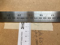
So from this starting point, I jogged the spindle along the Y axis for 480mm (a decent amount of 4 units without crashing the machine) and placed another piece of masking tape with crosshairs under the tip.
IMG_6671.JPG

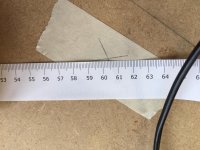
You're getting the idea, I jogged the spindle 360mm along the X Axis and placed the third piece of masking tape under the tip.
IMG_6672.JPG


So, two sides have come out accurate enough for now and I should have the three points of (I hope) a right angled triangle.
IMG_6679.JPG

Now comes the test. Measure the hypotenuse and if the machine is calibrated accurately, the the result should be exactly 600 mm.
IMG_6675.JPG

3.5mm out! Not accurate enough.

So, I manually moved one of the two Y axes lead screw assemblies 2mm back by manually turning the screw while there was no power to its stepper motor and repeated the process. This time it was 2mm out. Third time lucky!IMG_6676.JPGIMG_6677.JPG

Bingo! Result. The machine is now calibrated. Next I've got to 'Tram' the machine; i.e establish if the axis of the spindle is out relative to the spoilboard, and when I'm sure it's perfectly vertical, then I can machine the spoilboard flat.
 
Not really understanding how turning one Y lead screw squares up the X and Y axes but pleased it worked out for you. I'd have thought it would just go back to how it was once it was homed again. Obviously not.

Keep going :)
 
Thanks, Gents.

I'm not sure, Robert. I only turned one of the Y screws while the steppers were un-energised, so I believe the other Y (A) screw stayed where it was. I also moved the limit switch by the same amount and re-homed after each go at the triangle and the Y screw went to the limit switch. There isn't a limit switch on the other Y (A) screw.
 
Malc2098":wjh625kq said:
Thanks, Gents.

I'm not sure, Robert. I only turned one of the Y screws while the steppers were un-energised, so I believe the other Y (A) screw stayed where it was. I also moved the limit switch by the same amount and re-homed after each go at the triangle and the Y screw went to the limit switch. There isn't a limit switch on the other Y (A) screw.
Like Robert I was perplexed by your post but had over looked the two feed screws give scope for error. All clear now. Tramming my mill is a job I hate and go out of my to avoid tasks that need it to be used at an angle and then need to be reset.
Good luck
Bob
 
At last! I've finally managed to get it it fully working. Having overcome issues with Chinese and American hardware and software, it seems to be working as it should.

I know some of you have cnc machines and this might seem simple to you, but I have absolutely no background in engineering, electrics, electronics, software and all that is associated with them, and so it's been quite an achievement for me to get this far.

[youtubessl]qLZa2tNzZPw[/youtubessl]

https://youtu.be/qLZa2tNzZPw
 
Well done Malc.

Has it taken over your workshop or do you still have a plan to get it out of the way when not in use?
 
Thanks, Gents.

Beer and wine taken, Andy!

Absolutely, Bob. I had to have a lie down! Only thing is, there's guys in Romania, Aylesbury, Queensland and somewhere else all want to know my GRBL settings! :o

Honestly, Ian, I've had to learn stuff as I've gone along. But as members of a certain age know, when you learn some thing new, something older has to drop off the shelf!

Cheers, Robert. The plan is to hoist it up to the roof if the rafters can take it! I'm after one of them winches that you can wind up with a socket on a cordless screwdriver.

DaveL! You can go whistle……….for the time being. :)
 
Yer, but whi the beeeb is Alice?

(Not a chubby brown fan, it is the only thing I think I've ever seen of his)
 
novocaine":2l7y12n0 said:
Yer, but whi the beeeb is Alice?

(Not a chubby brown fan, it is the only thing I think I've ever seen of his)


Yeah. Alice Sophia is No 2 granddaughter.
 
Malc. Having got the machine to this level of functionality were any of the problems caused by insufficient/inadequate information provided by the kit supplier or mainly due to your lack of know how, errors in setting up?
I'm not knocking you in anyway but I'd have expected a kit supplier to have provided every last item of hardware/software/set up information etc that would be needed and that would be how they earn/justify their margin compared to buying the components individually.

Would any other kit supplier perhaps have been better with the benefit of hindsight?

Bob
 
9fingers":23qg3xjn said:
Malc. Having got the machine to this level of functionality were any of the problems caused by insufficient/inadequate information provided by the kit supplier or mainly due to your lack of know how, errors in setting up?
I'm not knocking you in anyway but I'd have expected a kit supplier to have provided every last item of hardware/software/set up information etc that would be needed and that would be how they earn/justify their margin compared to buying the components individually.

Would any other kit supplier perhaps have been better with the benefit of hindsight?

Bob
Bob, I looked at machines in the UK, Canada, US, Europe, Australia and China. The Chinese kit that I bought, is alleged to be an open source development of an Australian kit which I think is an OS development of a British kit, but I'm not too sure. Some of the Australians say the Chinese version is a rip off. But, given my lack of knowledge but desire to learn to use a machine, the Chinese version I bought represented best value for money. I have no problem with the quality of hardware. or how it went together. There assumes, by suppliers though, that there is a level of knowledge of why configuration etc is necessary of the VFD and the Controller. The VFD is Chinese, and the Controller is American, but supplied by the Chinese as part of the kit. The American designers of the Controller had not got their firmware quite right and relied on the likes of punters, like me, to tell them what wasn't working. Then they wouldn't reply to communications, and the Chinese would, but would always say it was the American designers' responsibility., while a chap in Aylesbury, banged the Americans' and Chinese's heads together to get them to acknowledge their responsibilities to customers. This has got things going but still hasn't created a plug and play situation. I am one of the few owners of the kit that has got it working properly.

It's also clear that customers across the world buy the kits and expect everything to be plug and play. It just isn't like that. There are so many controllers that there is not one standard. It is also clear that those same customers did little if any research before buying and expect everyone else on the online forums (fora) to tell the all their configurations. I think I eventually got mine working by being meticulous about shielding and grounding to eliminate the potential for EMI and by working with the Australian developers. They are good. The Laptop software is FOC and under continual development and that's what I use now to control my setup.

In answer to your question, I could have got the same, or should I have said a genuine, kit from the Australian supplier, but I would have been paying anything up to £2,000 more including the shipping.

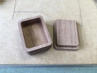
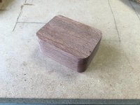
Anyway, here's my first attempt at a Tooth Fairy box. I've made a few mistakes, but I got the lid to fit perfectly.
BEE0E61C-72DE-4325-9DEB-175BECD07B0C_1_201_a.jpeg357D5078-CE46-4B52-8E0B-CBA8CC50B36F.jpeg
 
I foresee an awful lot of pleasure and fun emanating from that machine. As soon as you give the lucky recipient that box all the trials and tribulations of the setup will be forgotten.

Well done mate.
 
Thanks for the comprehensive reply Malc.
I had not realised the complexity of the various interactions of suppliers and designers involved with your machine and thought it was an out of the box kit that should not have needed so many issues to be solved.
Makes it all the more impressive that not only is it working but that you have had the tenacity to get it to this position.
Well done!
Bob
 
Thank you, Both.

I've just learned how to make 4 at a time out of two long pieces of wood! :D

All this learning, something else has got to drop out of my head! :lol:
 
Right! Now I've got it working and can practice with the Cad/Cam software, I also need to rip some stock and the machine is sitting on my table saw.

My shop is not big, 5.5 x 3.5m outside measurements, and I've got no floor space for a bench exclusive for the CNC Router. So, I've weighed it both ends with the bathroom scales and both readings are within 0.1kg of 25 kg, so I'm presuming around and at least 50kg AUW.

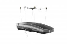
I've been thinking about a garage storage lift and came up with this.
https://www.thule.com/en-gb/cargo-carrier/car-top-carrier-accessories/thule-multilift-_-572004
578297.jpg

Its spec came up with up to 100kgs. The instructions talk of 1/4" lag screws into the rafters.

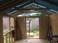
These are mine.A1D7F1A9-40A8-41ED-AEE1-84F35AA74409.jpeg
The ceiling is 11mm OSB, so I can find the rafters if I have to.

What do you guys think about hoisting 50kg via four pulleys, each fixed to the tie bar timbers by two lag screws?

I will, of course, be making a flat bed for the machine to sit on and it will be that bed that the ropes will be connected to.
 
I have the Thule lift it’s ok for a roof box but l wouldn’t be keen on hanging the cnc from it.
Would it being hinged from the wall be a better option ?
 
Cncpaul":3ehm4kzj said:
Would hinged from the wall be a better option ?

I have looked at those designs, especially the one that closes like DG window hinges, But I would have to lose so much storage space, racks, shelves etc from my walls, with nowhere else to move them to. As I said, my space is not big.
 
What about a tablesaw/router bed flip top stand on a slowmo motor connected to a PA that plays Thunderbirds each time you change use? That's what I'd do, honestly :lol:

If you can't be bothered then provided your rafters are big enough go with the pulleys
 
droogs":292fi9wd said:
What about a tablesaw/router bed flip top stand on a slowmo motor connected to a PA that plays Thunderbirds each time you change use? That's what I'd do, honestly :lol:

If you can't be bothered then provided your rafters are big enough go with the pulleys

:lol:

I'm thinking of bolts rather than lag screws through the ties, or through a couple of 4x2s bolted across the top of the ties, so as to spread the load across all three.

As an aside, back in the very early 70s, Century 21 studios had a place on my patch where they did the special effects. I had to renew their explosives licence.
 
I like that lifter, I could not have found a good use for that a few years ago, the lag screws or coach screws as I’ve always called them will take that weight with no problem, presuming 1/4” is the shank size. 2” long into a correctly drilled hole will take huge loads and you will be using 8 of them so looks good to me. Ian
 
Weight distribution is the key here.
50kg on 4 pulleys is 12.5 kg per pulley. if each pully is fixed by 2 bolts, then each bolt is holding 6.25 kg. Weight therefore is not an issue.
But I would be unhappy using rope or cord, purely because that situation could easily result in the load being held for a very long time, and the rope or cord might deteriorate and weaken if under constant stress. And there could always be an insect or mouse come along and chew through it, resulting in catastrophic failure (with apologies to will willis :eusa-whistle: )

I would use steel cable. It would be very thin and pliable and vermin proof.
 
Thanks, Gents.

Ian,

It's reassuring to know I'm on the right lines, assuming my tie beams can take the weight, too.

Bob,

Even more reassuring I'm on the right lines, assuming the tie beams can take the weight, too. I was also coming round to thinking of steel cable. I would suppose galvanised would be adequate, and stainless overkill for indoors. I'm not sure if nylon coated, like they use in gyms, not that I frequent any :) , would be OK going through the pulleys and around the coil wheels on the drive rod. Also, I'd have to think of what size of wire rope; the link to this suppliers state the 3-4mm has a breaking load a of 588kgs. I suppose that would do. ;)

https://www.wireropeshop.co.uk/nylon-11-steel-wire-gym-cable-clear/
 
Once you have it hoisted what will the clearance underneath be? How tall are you? Will moving stuff around the workshop be a problem?
I’ve not a better solution other than a workshop extension.
 
I have a small (5' x3') road trailer stowed in my garage roof hauled up by winch and rope but once in position, the weight is taken by short chains and the tension taken off the rope.
Something similar as a safety measure might be appropriate here too?

Bob
 
Back
Top