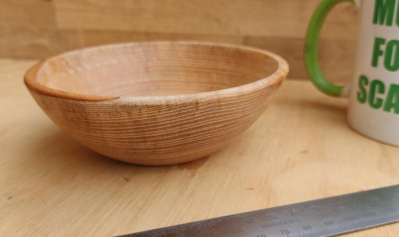
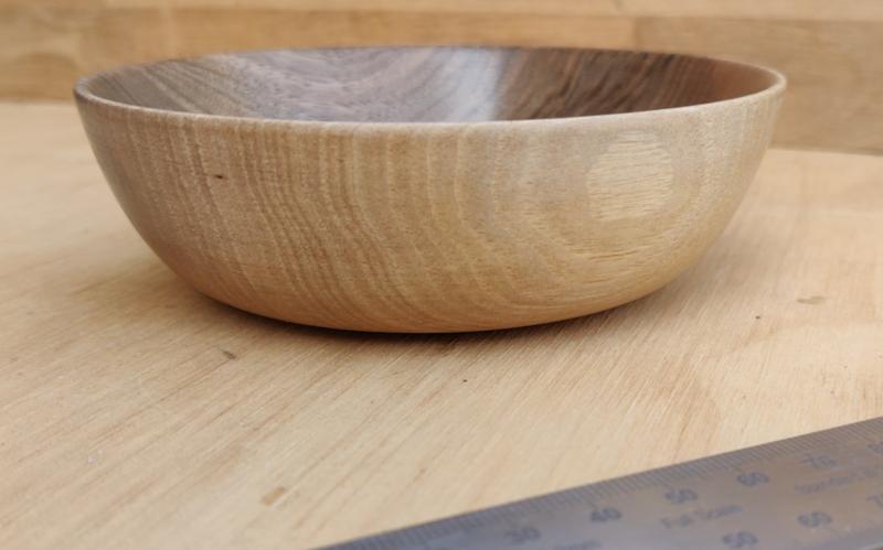
I forgot to say that you have made a nice bowl there. Will you keep the base like that?. I have come to prefer a ring foot, ie a a raised foot say 1mm wide. I find it is less likely to rock on an uneven surface.
Like this

Like this
Woodbloke":2lntdp04 said:What happens when somebody (the missus?) places a hypothetical order for a dining table to seat six+? :lol: - Rob

Andyp":2lntdp04 said:I forgot to say that you have made a nice bowl there. Will you keep the base like that?. I have come to prefer a ring foot, ie a a raised foot say 1mm wide. I find it is less likely to rock on an uneven surface.
Like this

Woodbloke":5tqcv5he said:Nice bit of spinning on the new lathe. If I could offer a suggestion for your next venture on 'the Dark Side', in my very 'umble opinion, bowls always look better if you can turn the walls an even thickness from the rim to the base.
")
Are you sure you haven't done this before?
Great stuff!!
And I love the engineer's approach of immediately testing the new tool to its designed limits.
)


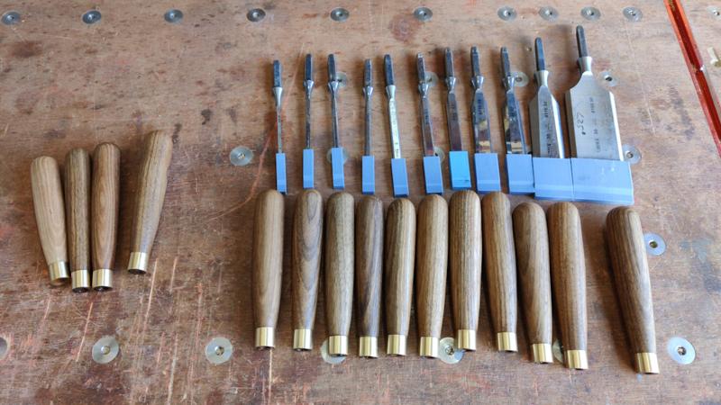
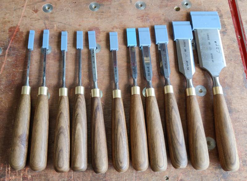
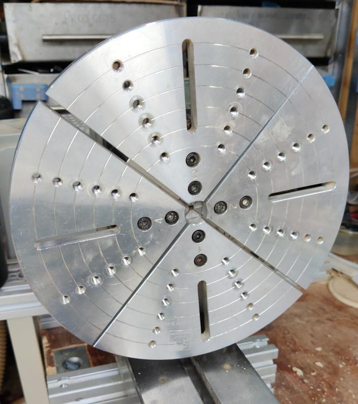
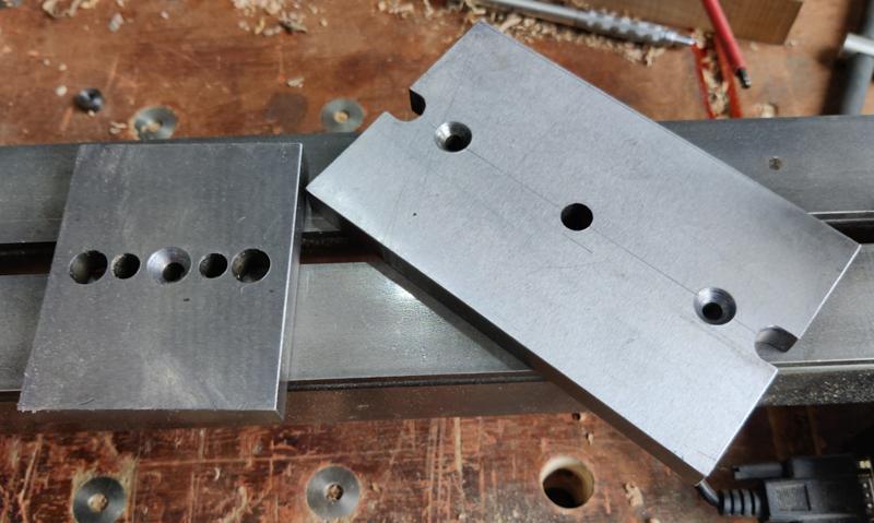
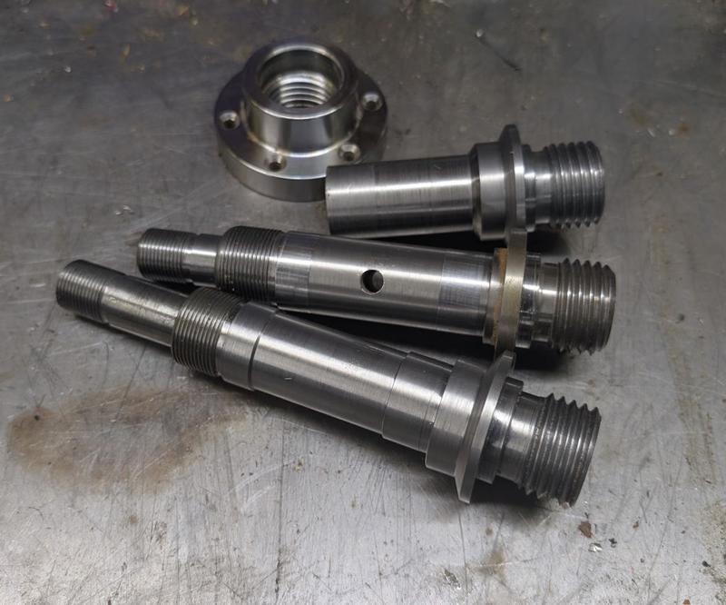
Why am I not surprised. Nice little earner you've got going there.Oh, and I got another one of these from the home-made tools forum (my fifth one apparently):
Ha! That's true, as long as you consider revenue and not profit!Why am I not surprised. Nice little earner you've got going there.

Getting the bottom of a box or bowl reasonably square with a flat base is hard going. I bought the Jason Breach set of tools which he designed specifically for this purpose; effective but not cheap. Then again Christmas is within sight! - Rob

Were you fooling us?…..Not that I'm going to make any more bowls... apart from the one I made today...
I bet rocking up at the course with your lathe raised an eyebrow or two.
The bowls look great by the way. Are you signing them? I know Rob likes to note the wood species on his pieces too.
Just noticed Al’s post from 1st April
Were you fooling us?
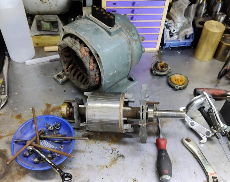
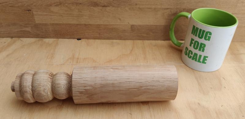
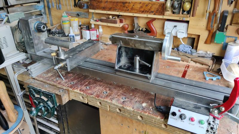
). Of course the danger there is that you rapidly end up with more bowls, pens and boxes than you know what to do with That is a very impressive lathe you made Dr.Al. Is there much vibration when turning using the mitre stand?I haven't been using the lathe much over the last few months, but I wanted to have a bit more of a go to try to improve my turning skills. Following some sound advice from @AndyP of this parish, I did a one-day woodturning course on Saturday with Paul Hannaby in the Forest of Dean. The morning was spent making this out of a lump of oak:
Okay, that doesn't look like much, but the idea wasn't to make something pretty, it was just to practise skew chisel techniques. It started off with practising getting a good finish on relatively straight sections, then we did some peeling cuts to reduce the diameter followed by cutting into a corner with a good finish. We then went on to cutting V-grooves and finally beads. I'd never tried cutting beads with a skew chisel so that was really quite challenging and the advice and suggestions were really helpful.
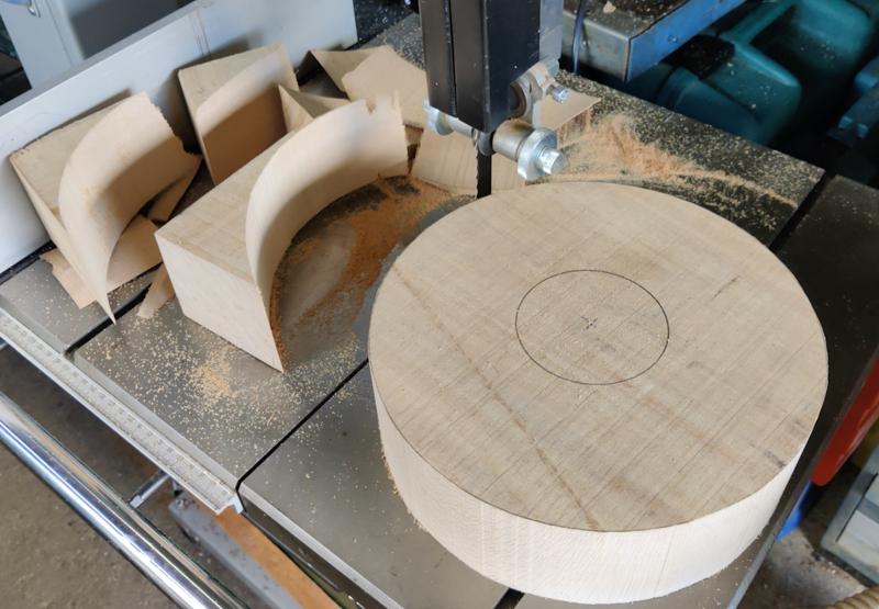
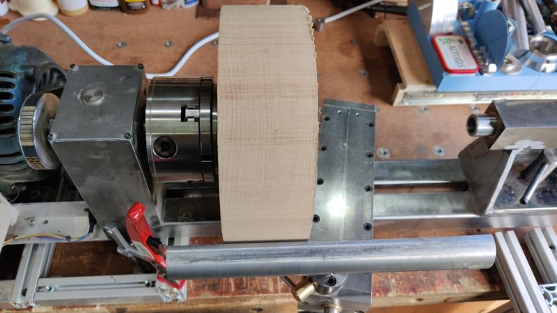
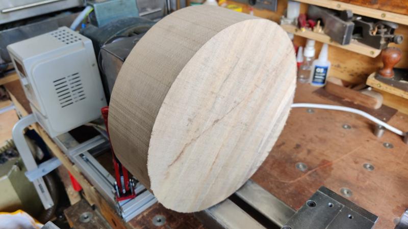
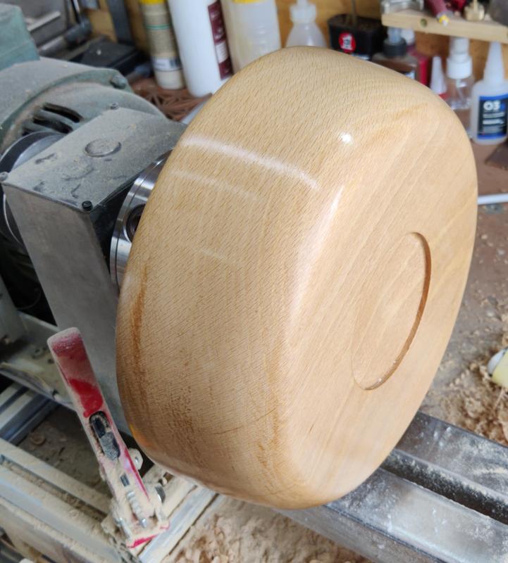
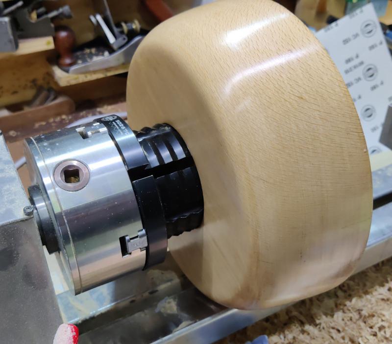
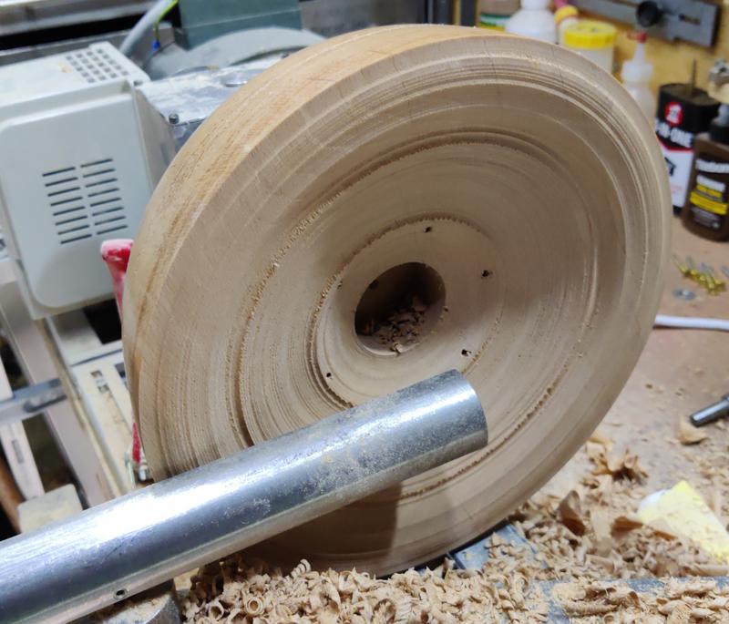
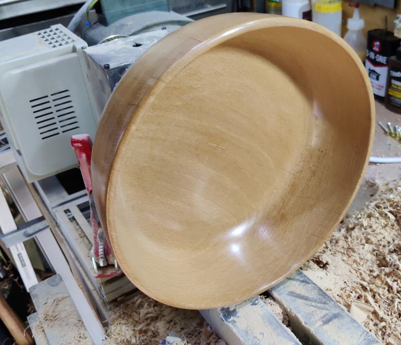
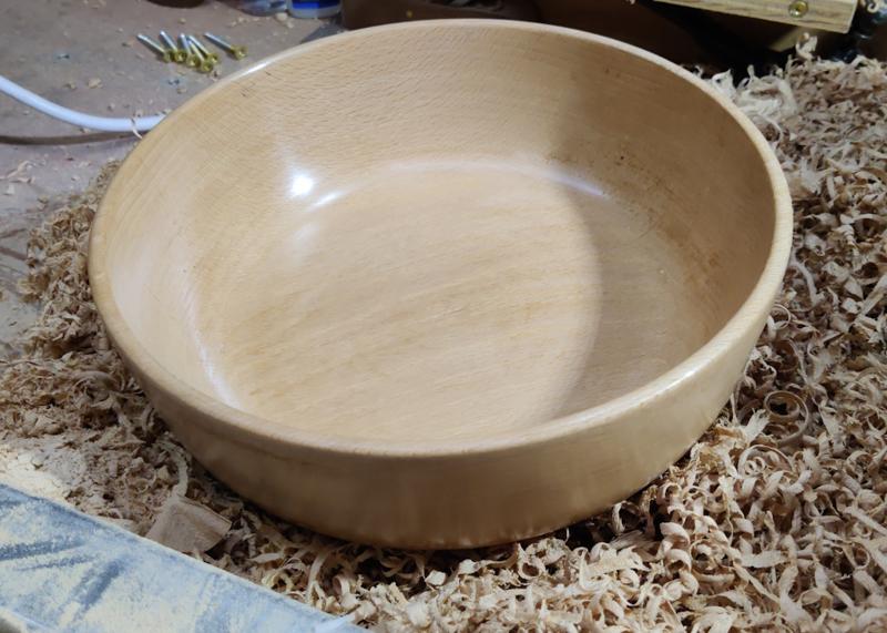
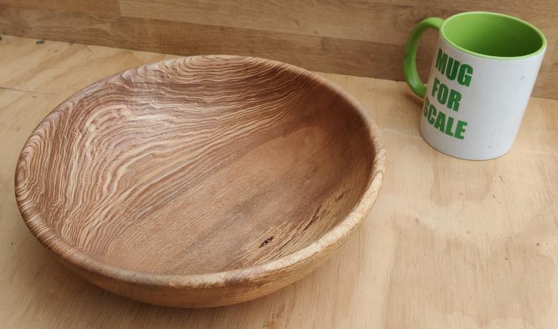
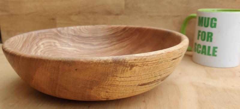
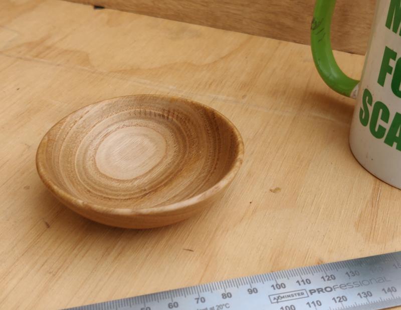
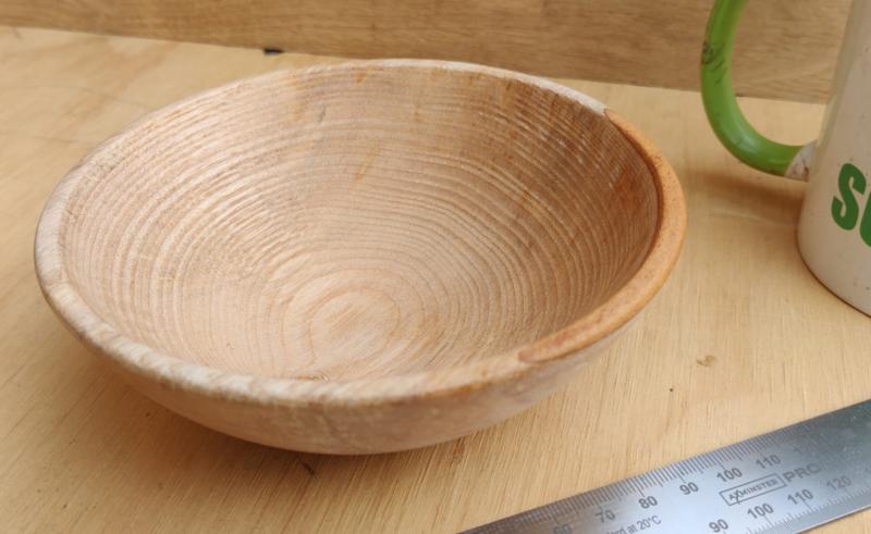
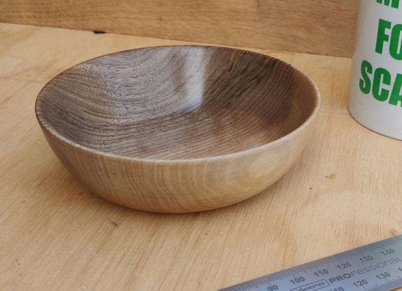
I started off the afternoon by making a bowl out of a lump of ash:
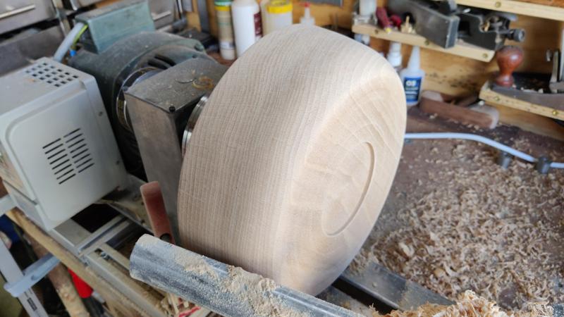
That was really instructive and definitely helped me feel a lot more comfortable using a bowl gouge than I had before the course. I decided to leave it unfinished during the course (to save time) and instead applied Mike's Magic Mix after I got home.
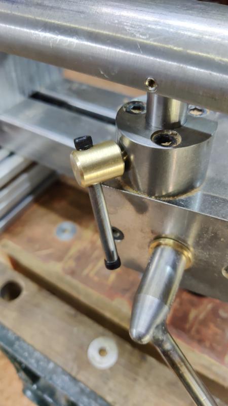
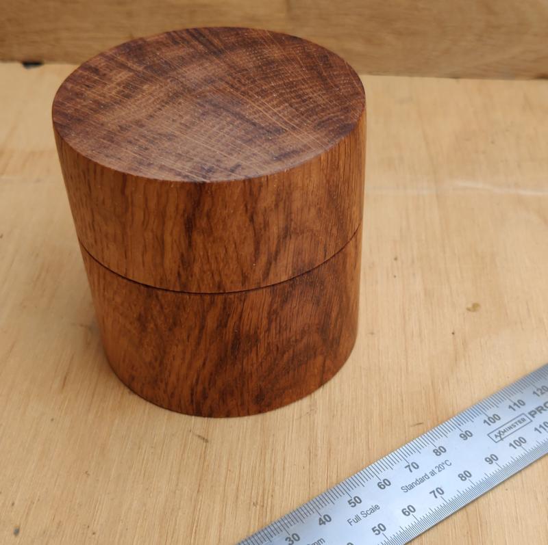
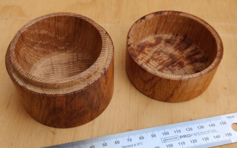
Once the bowl was finished, I made a small box out of brown oak (again finished with Mike's Magic Mix after I got home):
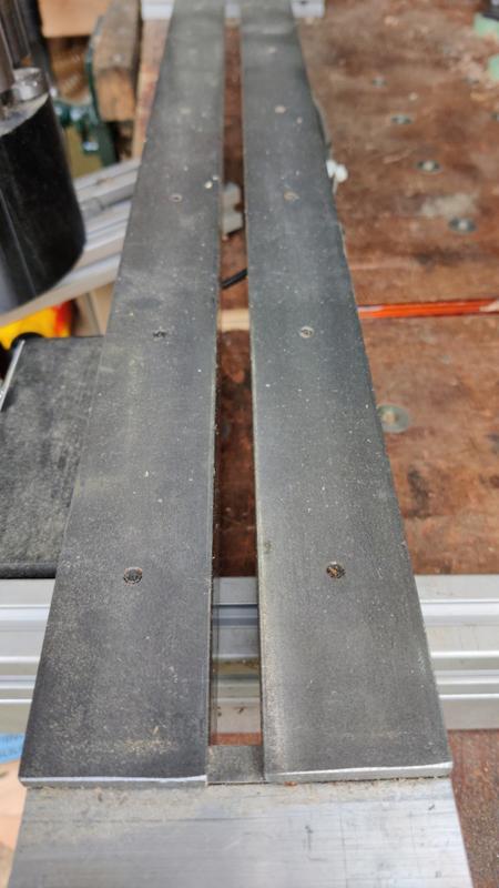
I really enjoyed making that box and I'd like to have a go at one myself sometime soon (although I might cheat and use a Forstner bit rather than doing everything with the lathe tools). He had a home-made hollowing tool that worked extremely well for cutting the sides and bottom of the box; I've ordered some 300 mm lengths of 12 mm high-speed steel so I can make one for myself (along with a round, square-ended skew chisel that makes beads much easier).
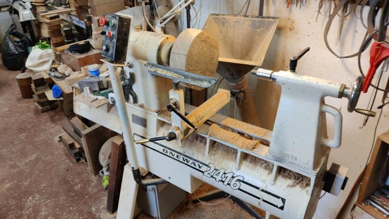
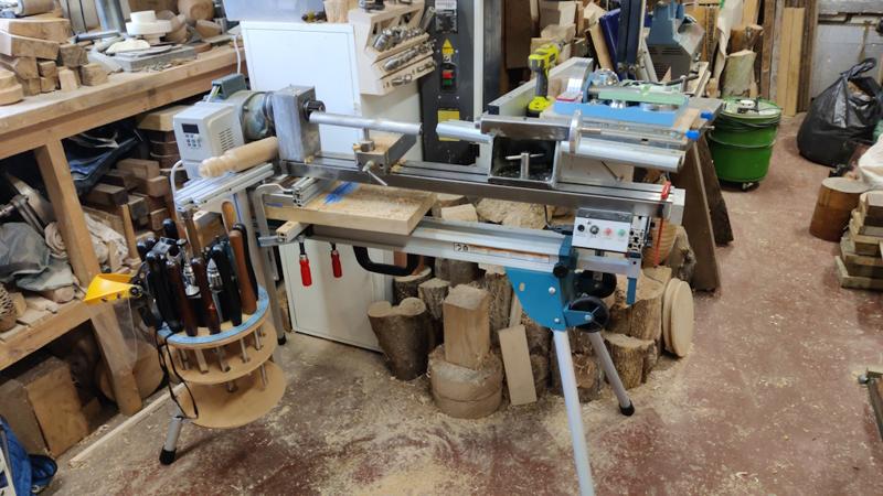
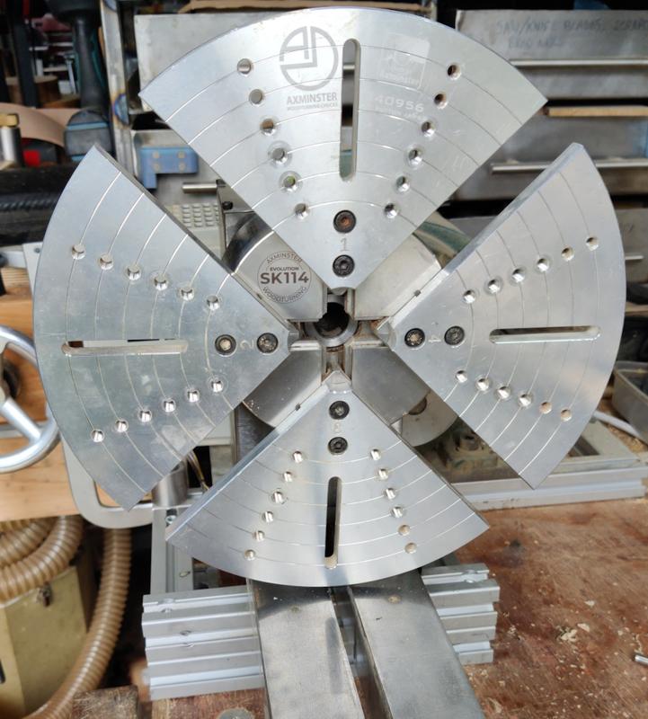
None of the above was done on my little lathe: I used Paul Hannaby's beast:
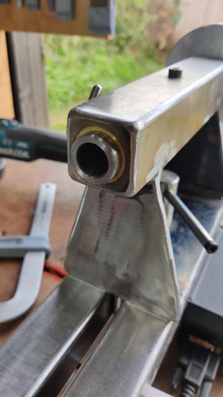
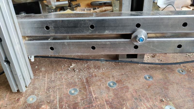
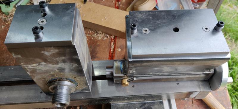
However, I did take my lathe along to the course and set it up on a mitre saw stand:
That enabled me to try the odd technique (mainly skew chisel stuff) on my own lathe so that I could convince myself that the improvements I was seeing in cutting action were a result of what I'd learnt and not just down to using a "proper" lathe.
Thanks duke. I haven't noticed much vibration but there are a couple of caveats there:That is a very impressive lathe you made Dr.Al. Is there much vibration when turning using the mitre stand?
Blimey......
b) that you have access to some very high grade skips

I think Mike is impressed....
 .
.