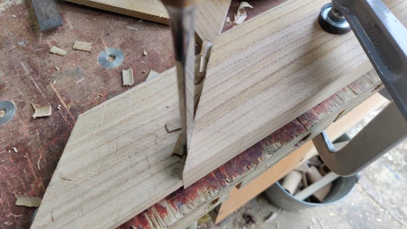
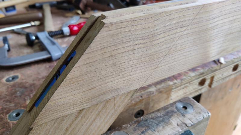
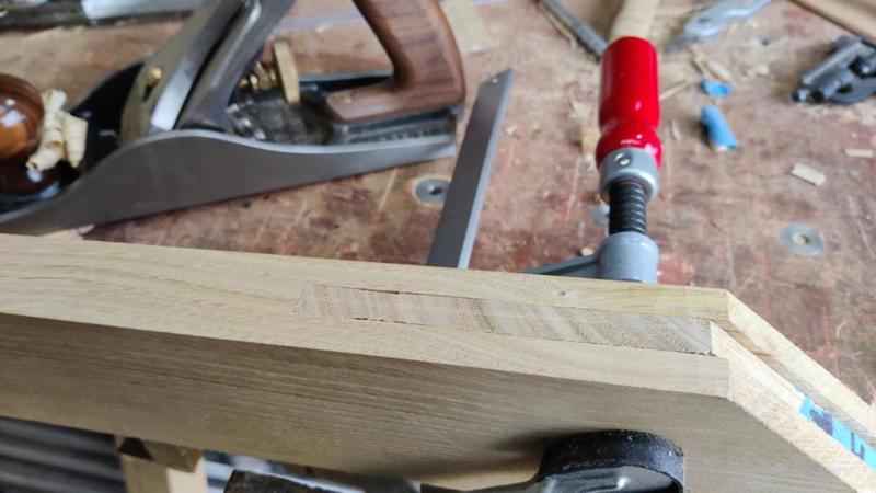
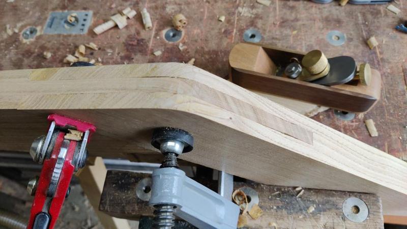
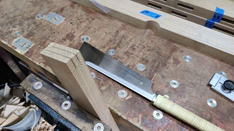
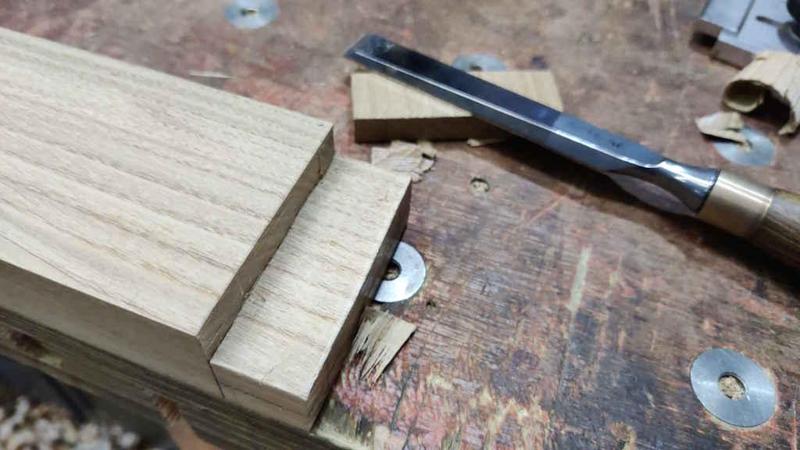
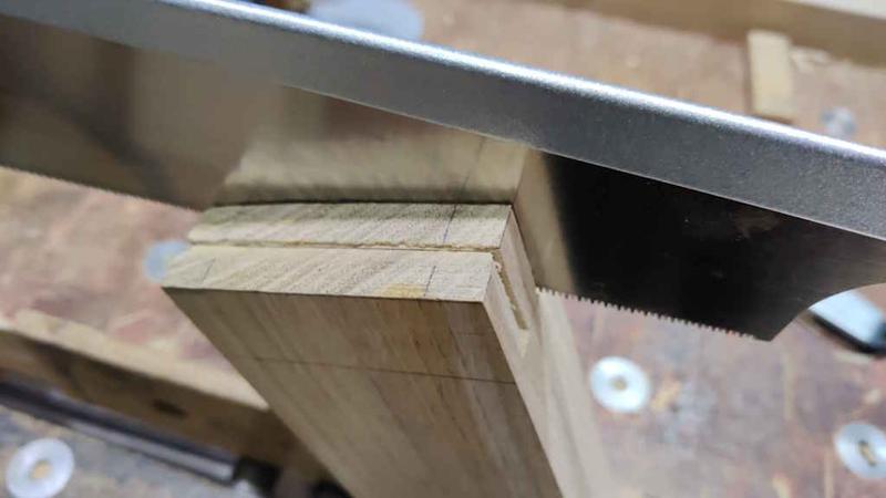
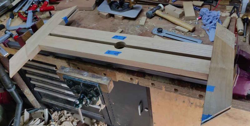
• Hi all and welcome to TheWoodHaven2 brought into the 21st Century, kicking and screaming! We all have Alasdair to thank for the vast bulk of the heavy lifting to get us here, no more so than me because he's taken away a huge burden of responsibility from my shoulders and brought us to this new shiny home, with all your previous content (hopefully) still intact! Please peruse and feed back. There is still plenty to do, like changing the colour scheme, adding the banner graphic, tweaking the odd setting here and there so I have added a new thread in the 'Technical Issues, Bugs and Feature Requests' forum for you to add any issues you find, any missing settings or just anything you'd like to see added/removed from the feature set that Xenforo offers. We will get to everything over the coming weeks so please be patient, but add anything at all to the thread I mention above and we promise to get to them over the next few days/weeks/months. In the meantime, please enjoy!

Garden Table

Now, can I persuade you to have a think about bridle joints... :)

I used them when I made 2 window frames. Was easy once I adjusted my mind :cool:

The thing about half-laps is that they don't need me to be especially accurate with a saw (i.e. I can roughly saw them and then deal with my inevitable inaccuracies later with a router plane or rebate/shoulder plane). Bridle joints are a bit more scary!
 
I imagine that you will be using M @T’s to join the centres to the outer ring Al? Should be interesting to cut as some of the mortices will be angled, I’ve looked at both designs and can’t see any huge problems down the line - just occasionally things are almost impossible to put together.
One thing that has me puzzled though is the apparent use of two thicknesses of wood glued together for the centre rail, (visible in the parasol hole).
At this stage before you go too far I think it might be advantageous to show us the cross frames for the legs. Sorry if I’ve missed it previously.
Ian
 
I imagine that you will be using M @T’s to join the centres to the outer ring Al? Should be interesting to cut as some of the mortices will be angled,

I was only planning to use M&Ts for the cross rail or cross rails (if there are two - see below). My current plan is to use dovetailed half-laps for all the other slats. The main reason for that is that it felt like it should be a lot easier to put together and also probably easier to cut. If we assume for a second that there's only one M&T cross rail, then the first "operation" is fitting that cross-rail and assembling the outer frame. That can then be left to dry. Once it's assembled, I can fit (or even cut and then fit) the dovetail half-laps for the slats.

I’ve looked at both designs and can’t see any huge problems down the line - just occasionally things are almost impossible to put together.

I am a bit concerned about @Mike Jordan's comment though. Any design I do that has any form of rigidity in both axes risks suffering from wood expansion problems. The only way I can think of that wouldn't involve that would be to have all the cross pieces running in the same direction, but that leaves the edges (two of the outer pieces) rather unsupported. I also quite like the look of the slats running perpendicular to the cross-rail.

One thing that has me puzzled though is the apparent use of two thicknesses of wood glued together for the centre rail, (visible in the parasol hole).

That was a response to a comment from @Mike G. My original design had a single cross-rail (with M&T joints) going in one direction and then a set of slats (with half-lap dovetails) going the other way. Mike suggested having two cross-rails with a halving joint in the middle (hence the two thicknesses of wood). I'm struggling to grasp why it would be stronger than the half-lap dovetails, but I thought I'd include it in the CAD model anyway for now.

At this stage before you go too far I think it might be advantageous to show us the cross frames for the legs. Sorry if I’ve missed it previously.

In all honesty, I haven't designed that bit yet, but I probably do need to get on with it soon. I'm not envisaging anything especially fancy, just four tapered legs with simple rails joining them together at the top, something a bit like this (but square and without the apron curves or the blowtorch effect!)
 
I don’t rate the use of buttons on the long sides of the apron in that illustration. When the top expands the leg joints may be damaged.
 
I don’t rate the use of buttons on the long sides of the apron in that illustration. When the top expands the leg joints may be damaged.
The illustration was just the first one I found that showed a rectangular (mine will be square) set of legs with an apron, not something that I was trying to copy exactly.

Having said that, I don't see buttons being an issue for damage as long as allowance has been made (either by having long slots or having long button "teeth" with a gap between the button body and the apron). The way the illustration is drawn has (bizarrely) the grain of the table top going along the short side, so the slotted holes in the long side of the apron allow for movement, as do the gaps between button and short apron sides.
 
"In all honesty, I haven't designed that bit yet, but I probably do need to get on with it soon. I'm not envisaging anything especially fancy, just four tapered legs with simple rails joining them together at the top, something a bit like this (but square and without the apron curves or the blowtorch effect!)"
Now that isn’t the type of table I was imagining at all. And I can’t quite see that top on that sort of base really.
To my way of thinking it needs to be a foldable X type frame so you can put it away for the winter months.
As ever Al it will be interesting to see what you end up doing.
Ian
 
"In all honesty, I haven't designed that bit yet, but I probably do need to get on with it soon. I'm not envisaging anything especially fancy, just four tapered legs with simple rails joining them together at the top, something a bit like this (but square and without the apron curves or the blowtorch effect!)"
Now that isn’t the type of table I was imagining at all. And I can’t quite see that top on that sort of base really.
To my way of thinking it needs to be a foldable X type frame so you can put it away for the winter months.
As ever Al it will be interesting to see what you end up doing.
Ian
It might be that you're right that it looks wrong. If so then hopefully it'll be obvious in the CAD model & I'll be able to come up with something else.

I'm not going to make it foldable though. Even if I did think that I might get round to putting it away, there's no space anywhere for it to go, so once it's in the garden, it's staying there. I might make a cover for it though (I say "I", but that's much more up Carolyn's street than mine!).
 
I can't quite believe it's been over 9 months since I last posted anything on this thread. Believe it or not, this project is still high on my list of things to do. Life went rather sideways last year with Carolyn's car crash and that slowed down the progress over the first half of the year (and to some extent over the second half as well) and then I had some other projects (in particular my heat treatment oven) that were best suited to working on them over the winter. With that and a few other bits and bobs here and there, the garden table project has slipped a lot later than I'd hoped.

Nevertheless, I still want to replace our ageing glass-topped garden table with something new and preferably wooden, so I want to get on with this now that I've pretty much finished the salt & pepper mills and have cleared the home-made lathe off the bench. I've got three fairly major projects I'm hoping to complete this year and two of them have fairly firm deadlines (albeit self-imposed ones). One big project (which will appear in a new thread shortly) needs to be completed by the end of August and the other (somewhat smaller) project needs to be finished by mid-October (but we're away for a sizeable proportion of September so realistically both probably need to be done by the end of August). I'd really like the garden table to be out of the way (both figuratively and literally) by the time I start the next project and that means I need to get on with it as soon as possible.

The (self-imposed) pressure also means I've decided I'm going to further weaken my hand-tool only resolve. If you remember back to the start of the project, I said this was going to be made mostly with hand tools and then (following the other half's car accident and the resulting loss of workshop time) resorted to using the bandsaw for the long rips. I've now decided I'm going to embrace that approach a bit more and use the bandsaw wherever it will give a substantial benefit. I'm also not ruling out using the thicknesser if it'll speed things up enough to be worth it. There will still be lots of hand toolery in the project though: I don't own a surface planer so I have to do that step by hand and I'd rather avoid the screaming monster (electric router) or if I possibly can. I also have no intention of doing any sanding on this project as I hate sanding and prefer the look of a cleanly hand planed surface.

Anyway, well done if you've managed to keep reading this far without getting bored of my waffle.

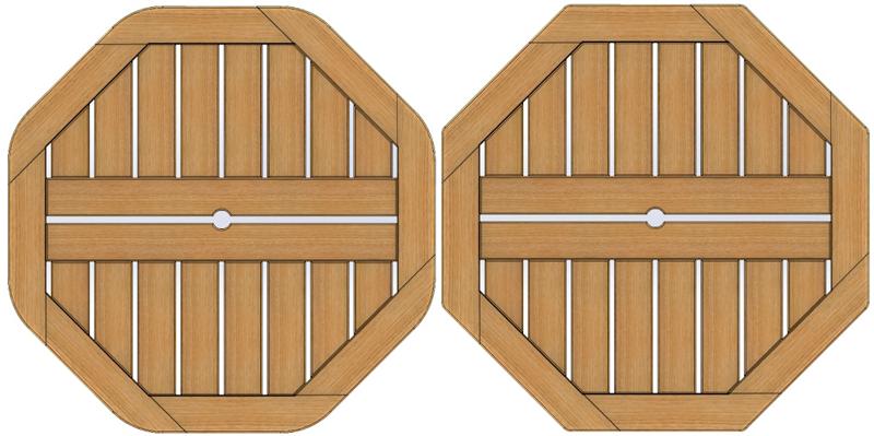
The design has progressed a bit since the last time I last showed it and I'm feeling reasonably pleased with it at the moment (note though, that I have yet to gain approval from the "design authority" so all may change again!). This is what it looks like at the moment in the CAD model:

2025-03-25-02-latest-design-top-down_800.jpg


I'm not completely sold on the rounded corners, hence the two versions of the design, but I'm not going to worry about that for now. Rounding the corners off will be one of the last steps in the table-top build so I can decide on the radius or ditch the rounded off corners completely later. The main thing that's changed since the last CAD model I shared is that I've split the central cross-bar into two pieces. I think that helps with the issue of wood expansion: the cross-bars can expand into the gap between the two of them rather than trying to compress the other slats lengthways.

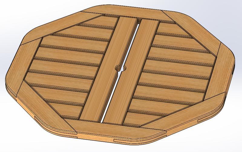
2025-03-25-01-latest-design-overview_800.jpg


As you can see in this image, I've also taken the (rather brave/stupid in my opinion) decision to use bridle joints rather than half-laps. I've never cut a bridle joint before, so that aspect could be quite challenging! If I'm honest, thinking about that joint was part of the reason I decided to bite the bullet and accept that the bandsaw will be used a lot more than I was initially planning. The rip-cut parts of the bridle joints will probably be much easier with the assistance of a bandsaw and I can put off learning to do it completely by hand until I've got more time. The joints between the main cross-bars, slats and rim pieces are all currently drawn in the CAD as mortice and tenon joints, but I'm quite tempted to do M&Ts just for the cross-bars and half-lap dovetail joints for the shorter slats. The advantage of that is that I can assemble the outer frame and cross bars first, wait for the glue to dry and then mark out and cut the half-lap dovetail joints afterwards. That feels like it'll result in a much less stressful glue-up.

Oh, for a sense of scale, the table top as drawn is 900 mm across flats and 32 mm thick.

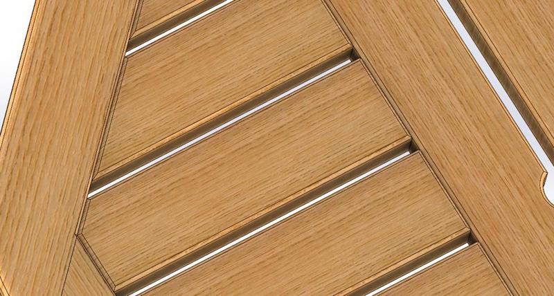
2025-03-25-03-latest-design-detail_800.jpg


This photo shows a close-up of the slats. I've designed them in the CAD to have a light (3 mm-ish) chamfer around the faces. The advantage of that is that I can much more easily run a plane across the top surface, using the gaps from the chamfer as a starting and stopping point and hence not having to worry about the edge of the plane knocking off a corner somewhere. If I pick the edge board orientation right I might be able to plane all the way around the rim boards in the same direction (clockwise or anticlockwise, but not changing direction from one board to the next). Having said that, I think picking the edge board orientation right might be impossible as a result of the way I chopped up the boards to minimise wastage).

The potential disadvantage of the chamfers around the joints is that it could give water somewhere to sit, which would be far from ideal, so I might yet have to ditch that feature. Comments/thoughts welcome as usual.

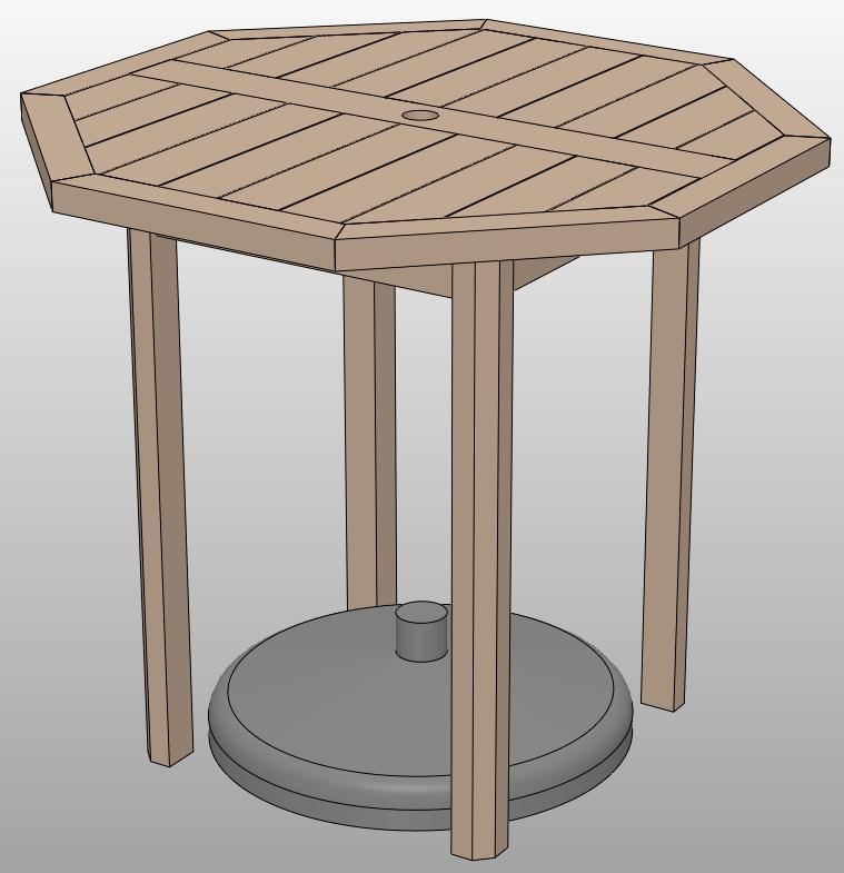
I've still got to figure out the base of the table. At the moment I'm still leaning towards a very simple and fairly conventional table base construction, with four legs and some rails between them (probably with mortice and tenon joints into the legs and buttons attaching the table top). That would make it look something like this very old (and out of date) CAD model:

2025-03-25-04-old-model-with-legs_800.jpg


I have no plans for the table to be put away for the winter (I don't have anywhere to put it!) so there's no point trying to make it collapsible. The main issue I see with the simple legs-and-rails approach is that the top of the rails might look a little odd when viewed through the gaps between the slats in the table top. I don't have any better ideas at the moment though!

Comments on any of the above would be very welcome.
 
Well, today was a good example of why "measure twice, cut once" isn't necessarily sufficient. Sometimes it's a good idea to "think three times, measure twice, cut once"!

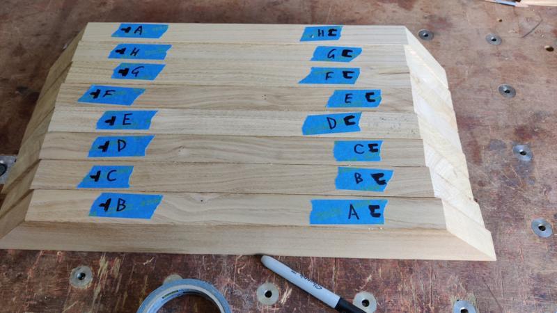
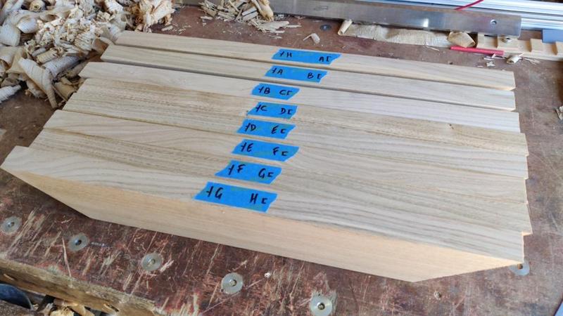
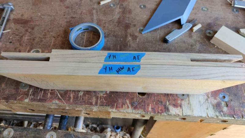
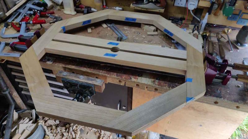
I started by getting all the planks I prepared back in August and labelling them to show which order they'd be assembled around the ring. There are three that will need to be planed in one direction and five in the other, so I made sure the three were next to one another. In practice I may just plane it with a high angle plane (which seems to work fine on this sweet chestnut), in which case the grain direction isn't as critical.

2025-03-29-01-labelled-planks_800.jpg


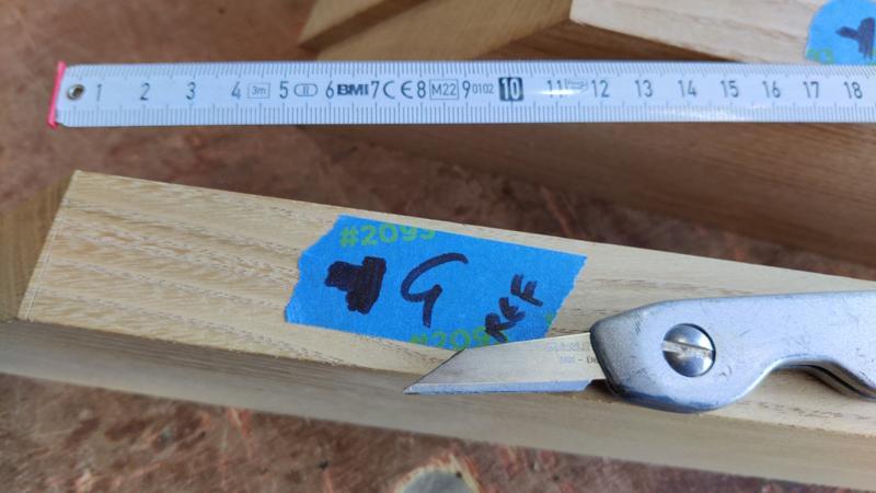
I picked the shortest of the planks and used it to choose a distance between edge marks. The distance I picked was 372 mm; that will form the length of a side of the octagon. That should result in an octagon that is 972 mm across corners and 898 mm across flats.

2025-03-29-02-marking-reference-shoulders_800.jpg


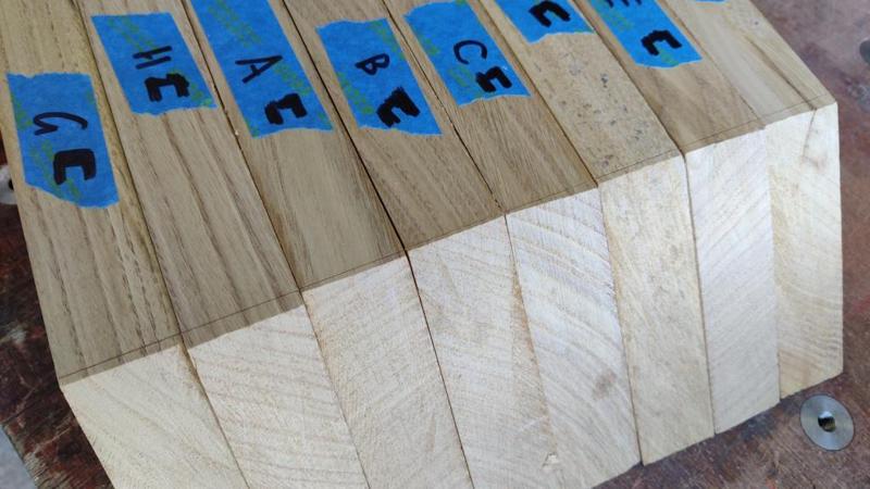
The shoulder marks from that reference board were then transferred to all the other planks, which should result in a regular octagon if I don't mess anything up.

2025-03-29-03-transferred-shoulders_800.jpg


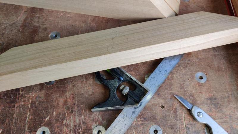
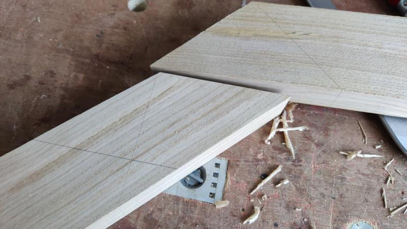
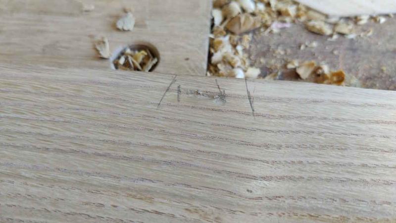
I then used a combination square to transfer those marks all the way around the plank, marking the outside on the ends that will have the outside bit (socket) of the bridle joint and just marking the ends on the tenon end. All very precise, but in completely the wrong place. More on that later.

2025-03-29-04-spot-the-mistake_800.jpg


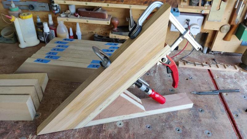
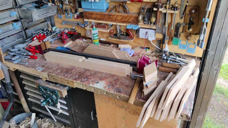
I knocked up a very quick and simple jig for the bandsaw out of some off-cuts of 25 mm plywood that I'd been given by a neighbour:

2025-03-29-05-jig-for-bandsaw_800.jpg


Despite never having cut a bridle joint before, I decided to just go for it with these planks rather than doing a trial run on a scrap board. The reason for that was a combination of a few factors:

  1. I didn't have any prepared wood of a similar-ish thickness (or material);
  2. I've (thankfully) got plenty of sweet chestnut, so messing up one or two pieces won't be the end of the world;
  3. It can't be that hard, can it?!

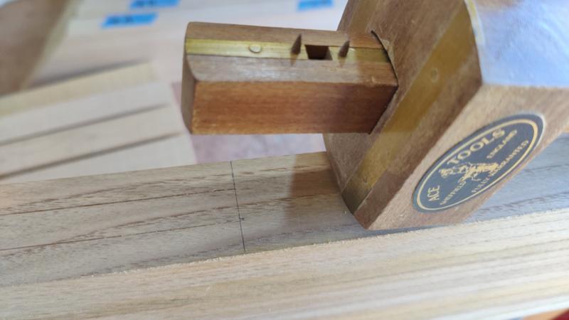
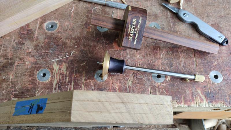
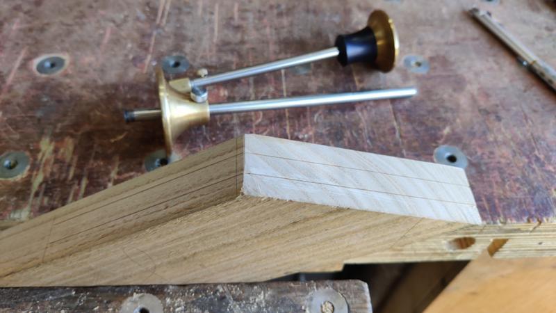
To mark the rip-cut lines, I used a mortice gauge on the first joint attempt:

2025-03-29-06-mortice-gauge_800.jpg


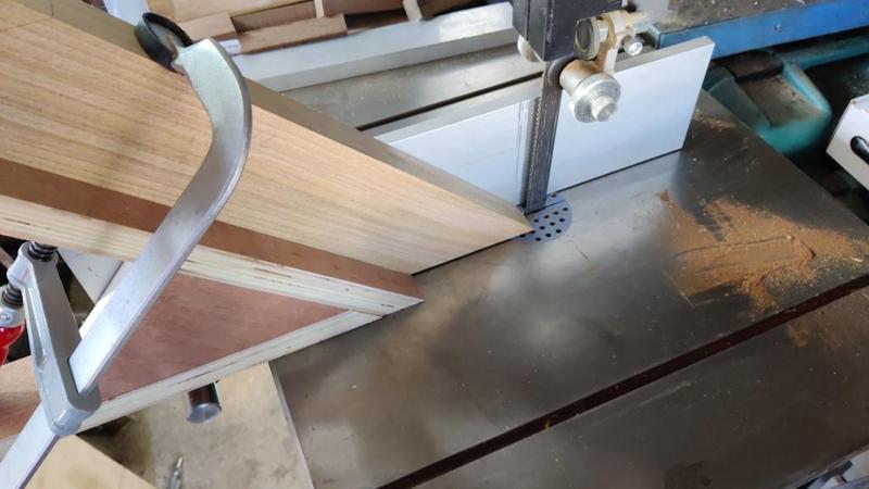
Bandsawing was done with the part pushed against the fence, using the scribed lines (later reinforced with pencil) to set the fence in the right place:

2025-03-29-07-bandsawing_800.jpg


After the first cut, it was clear that the bandsaw needed adjustment:

2025-03-29-08-bandsaw-needs-adjusting_800.jpg


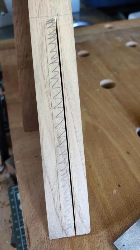
I did a central cut, partly to check the adjusted bandsaw accuracy and partly to make it slightly easier to get the waste material out later. After the adjustment, the cuts were much better:

2025-03-29-09-better-on-other-cuts_800.jpg


Things went nice and smoothly on the other part as well, this time cutting on the other side of the gauged lines:

2025-03-29-10-two-bits-with-rip-cuts-done_800.jpg


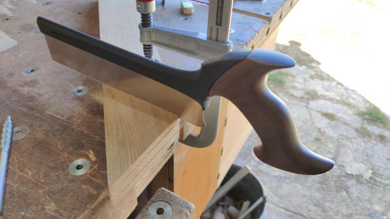
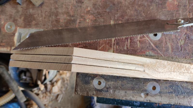
For the tenon piece (is that the right name?), I used a western-style cross-cut saw for the first side...

2025-03-29-11-western-cross-cut-saw_800.jpg


... leaving a bit of waste to be chiselled out later:

2025-03-29-12-leaving-room-for-chiselling_800.jpg


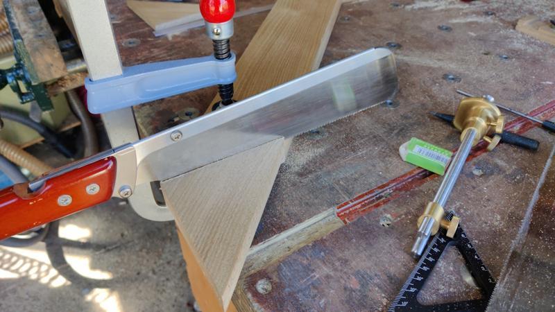
For the other side, I switched to a cross-cut Dozuki:

2025-03-29-13-japanese-crosscut-saw_800.jpg


I quite like trying out the different types of saws when trying new techniques as I find some things better with one and some with the other. It didn't make much difference in this case really.

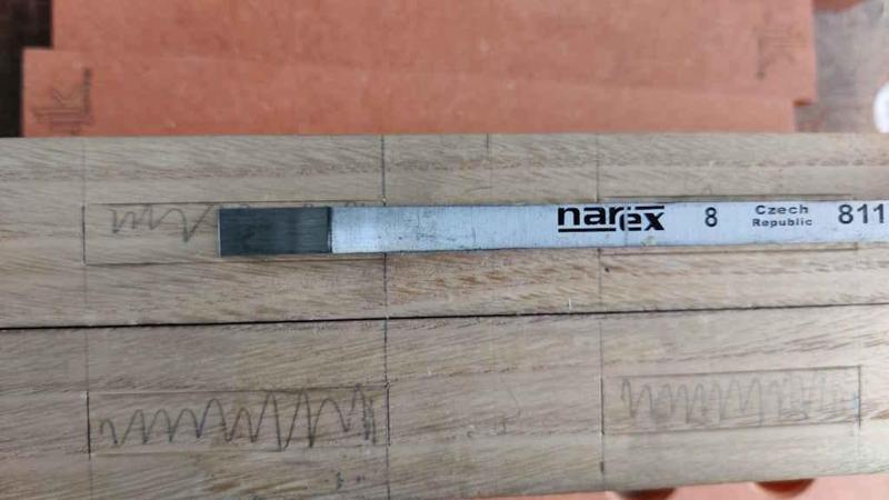
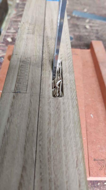
To clean out the socket, I started with an 8 mm mortice chisel (the socket is about 11 mm wide), going straight down first of all:

2025-03-29-14-roughing-out-with-mortice-chisel_800.jpg


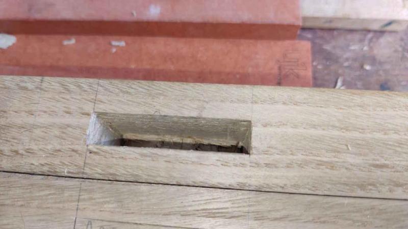
That left it looking like this when I flipped it over:

2025-03-29-15-flipped-over_800.jpg


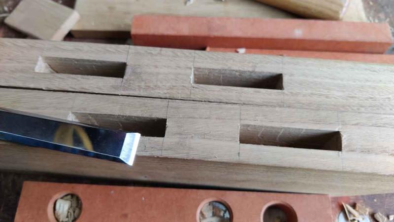
I could then carry on chiselling to get it close to the line:

2025-03-29-16-mortice-chopped_800.jpg


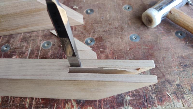
I then switched to a bevel edged chisel to clean up the bottom:

2025-03-29-17-tidied-up-bottom-with-bevel-edge-chisel_800.jpg


A bigger one was used to clean up the sides:

2025-03-29-18-cleaning-up-rip-cuts_800.jpg


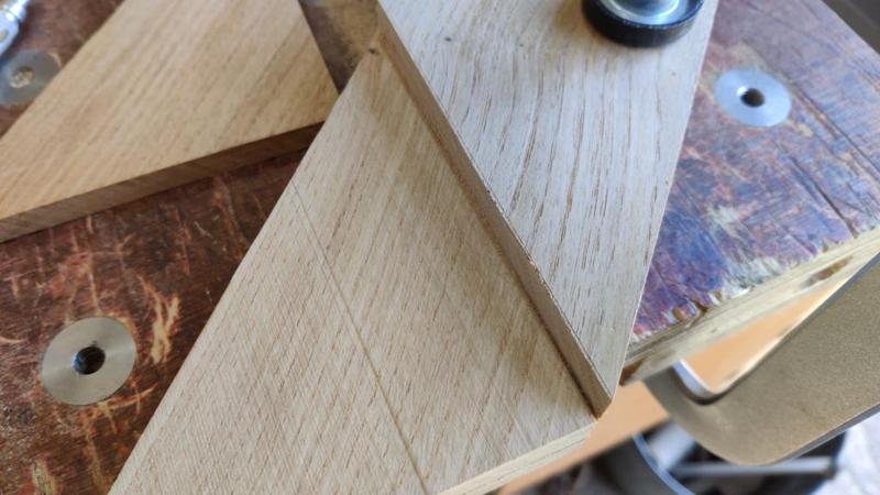
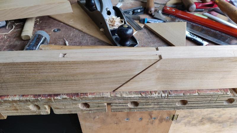
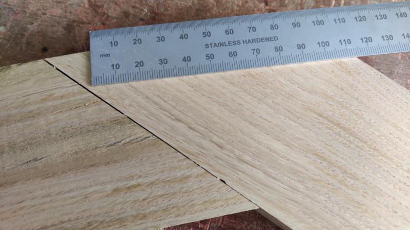
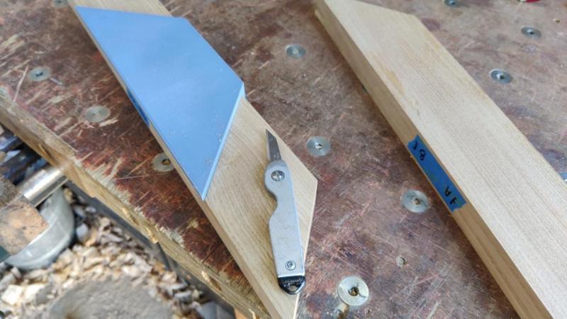
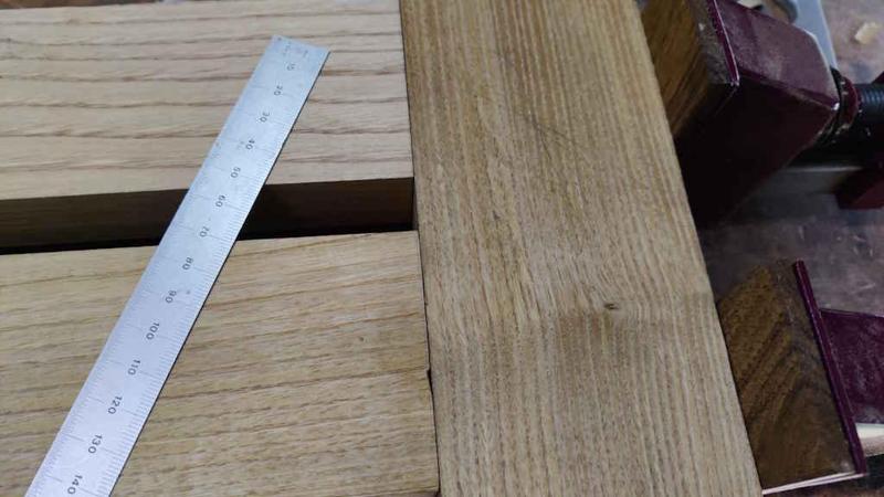
At this point, I started looking at doing a test fit to see how well they sat together and that's when I realised I'd marked them up completely wrong and they'd never go together correctly. In this photo (of two other planks), the knife line (on both planks) is where I'd marked them up; the pencil line is where I should have marked them up:

2025-03-29-19-how-i-should-have-cut-them_800.jpg


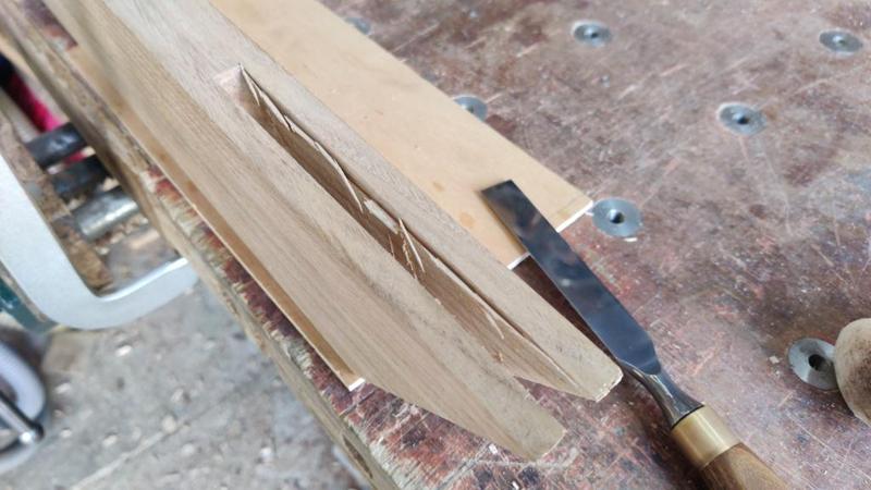
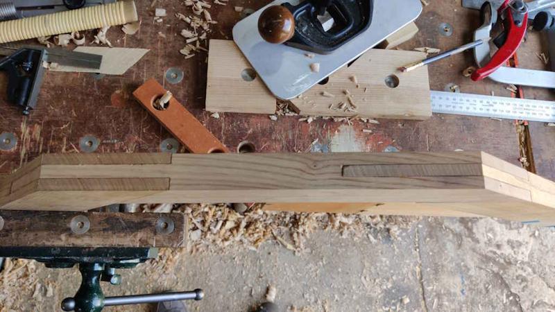
Nevertheless, I carried on getting them to fit together, using a carriagemaker's rebate plane to tweak the tenon until they slid together (with some sizeable gaps around the edge, plus some humongous gaps where I hadn't got round to chopping the shoulders yet):

2025-03-29-20-test-fit-anyway_800.jpg


Those two pieces are now waste (but thankfully, as I said, I have more sweet chestnut - I see lots more hand planing in my future!)

Continued in the next post...
 
As I said, those pieces are waste, but I decided to use the other end of them for another practice (marking them out properly this time). In general, the marking proceeded much as before, but this time I used two separate gauges rather than a mortice gauge:

2025-03-29-21-different-marking-gauges_800.jpg


I prefer that method as it's a bit more controlled to mark with a single pin at a time. I've got a wheel type mortice gauge that makes it quite easy to use one wheel at a time (vs the pin one that makes it just about impossible), but I still prefer having two separate gauges I think.

This time, I decided to try doing the rip cuts with a Ryoba, starting (with the socket board) by following the line carefully on two edges...

2025-03-29-22-ryoba-for-socket_800.jpg


... then flipping it over to follow the line on the third edge.

2025-03-29-23-flipped-ryoba_800.jpg


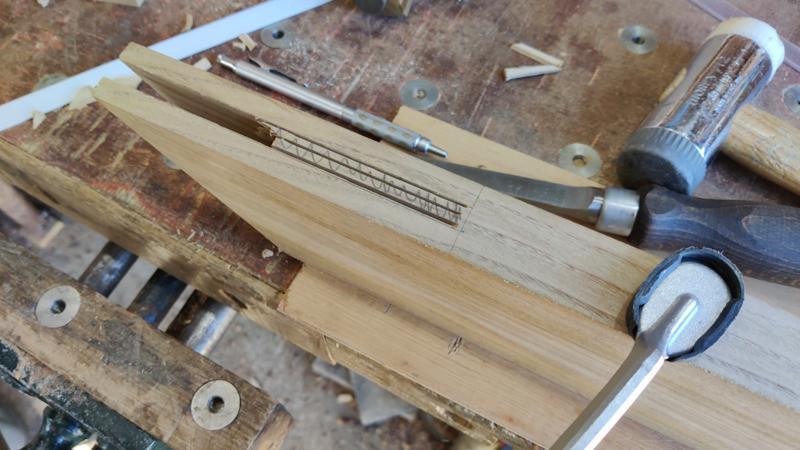
I then flipped it over again and sawed parallel with the base line to take out the middle bit. Sawing with the Ryoba seemed to work well, but I'm definitely not ruling out going back the bandsaw on later ones. With the rip cuts done, I used the 8 mm bevel-edge chisel to form a small flat section near the bottom of the socket and an awl was used to make a dimple in the middle of that flat bit:

2025-03-29-24-chiselled-flat_800.jpg


I could then use a tip suggested in Charles Hayward's Woodwork Joints: drilling along the baseline with (in this case) an 8 mm drill bit:

2025-03-29-25-8mm-drill_800.jpg


That very quickly removed the bulk of the waste:

2025-03-29-26-release-part_800.jpg


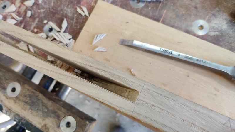
From there, it was quite a long-winded exercise of trimming the bottom of the socket and paring the sides:

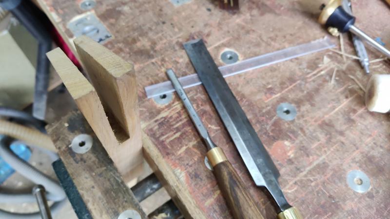
2025-03-29-27-pared-socket_800.jpg


I found it very difficult to have any confidence that I was doing a good job of paring, but I felt moderately (but unjustifiably!) confident eventually.

Once the socket was complete-ish, I moved on to the tenon piece, again using the Ryoba for the rip cuts:

2025-03-29-28-ryoba-tenon_800.jpg


The cross-cut Dozuki dealt with the shoulder cuts, again leaving some room for chiselling along the knife line later:

2025-03-29-29-crosscut-dozuki_800.jpg


To clean up the tenon, I started by using a router plane with a 19 mm cutter this time, working out as far as I could while still keeping the base on the face of the plank:

2025-03-29-30-router-plane-where-it-reaches_800.jpg


I'd pondered using one of the other planks next to the end to provide a bigger surface, or to put a bigger base board on the bottom of the router, but I decided in the end to just leave it there; partly because the end of the tenon is unsupported underneath and I wasn't convinced the router would work that well without packing material under the end. Instead, I used the paring chisel to clean the end up as carefully as I could:

2025-03-29-31-paring-chisel-for-rest_800.jpg


I could then do a quick test fit:

2025-03-29-32-test-fit-before-shoulder-cutting_800.jpg


The scribe lines don't meet as a result of not having chopped the shoulders yet, so that was the next job (one that I really enjoy):

2025-03-29-33-chopping-shoulders_800.jpg


After chopping the shoulders it was looking okay (if a bit gappy around the actual joint, which you can't see in this photo):

2025-03-29-34-test-fit-after-chopping-shoulders_800.jpg


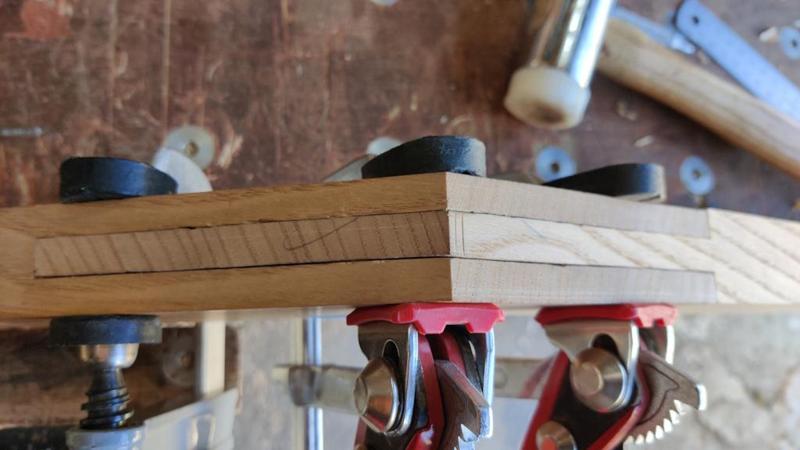
I didn't want to glue this joint together as it's just a scrap piece now, but for an approximation of how it would be in the end I thought I'd stick a clamp (and later a second one) across the face to simulate the glued joint. I could then use my Clifton #4½ to bring the ends of the boards down to meet the faces:

2025-03-29-35-clifton-plane_800.jpg


After doing the second face, I used my home-made block plane to do a gently round-over on the corner:

2025-03-29-36-rounded-corner-bit-gappy_800.jpg


With the sides planed, you can now see the gaps around the joint. It's a lot better than the first one I tried, but it's far from perfect. The tenon seems nice and straight, but I didn't do a great job of the socket.

Tomorrow I'll have another go (probably using the same boards) to see if I can do a better job of cutting that socket, but I might also do some more reading of Charles Hayward et al for any handy tips!
 
If you’re shoulders don’t meet run a saw down the joint, it’s called kerfing in you take a little off each side.

Pete
 
If you’re shoulders don’t meet run a saw down the joint, it’s called kerfing in you take a little off each side.

Pete
That sounds like a useful trick for the shoulders. On my practice pieces the shoulders were okay; it was the long joint faces that were the problem & I think a saw cut would just open it up more unless I'm missing something.
 
That sounds like a useful trick for the shoulders. On my practice pieces the shoulders were okay; it was the long joint faces that were the problem & I think a saw cut would just open it up more unless I'm missing something.
I have made some triangular trivets with really tight joints by going round kerfing in a couple times until all the joints are tight. It’s just a matter of kerfing in the tight shoulders until the gaps have gone.

Pete
 
Last edited:
steve.JPG

Did I see you at a YMCA concert, by any chance, Steve ? Working as a bouncer ? You look the part and I wouldn't fancy my chances of gatecrashing ! :)
 
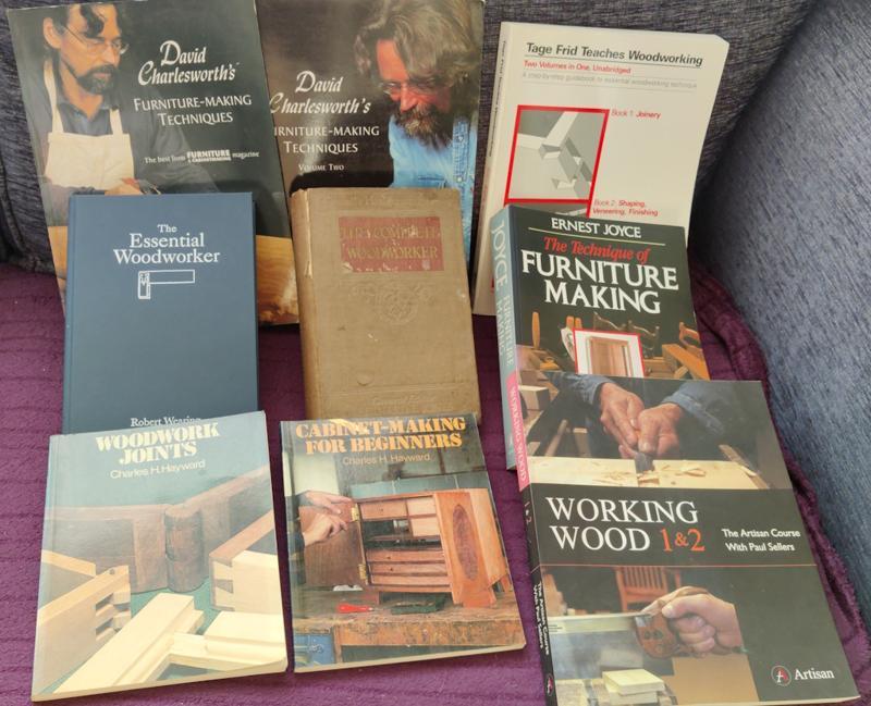
The clocks have sprung forward and that always lifts my spirits as we can look forward to light evenings for the next 7 months. I wanted to spend today having another go at bridle joints as I wasn't very happy with how gappy yesterday's result was. Before I starting, I assembled my favourites out of my (much larger) collection of woodworking books to look for advice on cutting bridle joints:

2025-03-30-01-favourite-books_800.jpg


Surprisingly, while a lot of those books mention bridle joints in passing and perhaps have an image showing what they are, the "Woodworking Joints" book by Charles Hayward is the only one that gives any advice specific to that type of joint. I still felt like I needed a bit more advice so I went back and rewatched this youtube video:


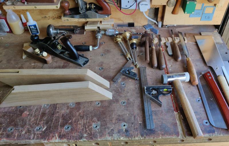
It was definitely worth watching it again as it refreshed my memory on what I should be doing when forming large glue surfaces on both parts. To kick the day off, I had a bit of a clear up and assembled the main tools I expected to be using on the next attempt:

2025-03-30-02-assembled-tools_800.jpg


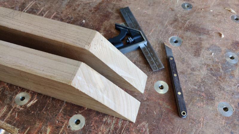
Those planks of sweet chestnut are getting a bit short now (having been used for two attempts already), but there's enough length there for another go. I started by marking a line (with a recently home-made marking knife) for the end of the planks, avoiding a bit of torn out wood on one of the planks:

2025-03-30-03-marking-new-start-lines_800.jpg


Two gauges (both wheel type this time) were used to mark the rip lines:

2025-03-30-04-gauge-lines_800.jpg


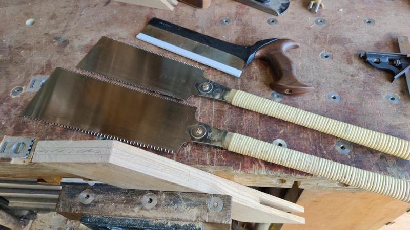
For this attempt, I decided to use my massive Ryoba, seen in this photo next to the small one and a Veritas saw for scale:

2025-03-30-05-big-saw_800.jpg


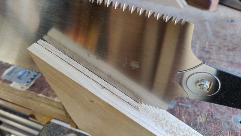
That big saw is very good at resawing type cuts (which this essentially is). Nevertheless, I stayed about a millimetre away from the lines...

2025-03-30-06-keeping-clear-of-lines_800.jpg


... and was glad I did as, when I was cutting the second edge (on an acute angle, so I could only see one face at a time), the saw wandered very slightly but still stayed on the correct side of the line:

2025-03-30-07-glad-i-kept-clear_800.jpg


Matt Estlea's video had suggested that one option for clearing the waste was a fret saw. The blade on my fret saw isn't long enough to have much of a stroke across the angle of this cut so I thought I'd try the coping saw (which fits in the kerf thanks to having used the extra-large Ryoba):

2025-03-30-08-coping-saw_800.jpg


Even with the coping saw, there really wasn't much opportunity to move the saw back and forth and, while it worked, I don't think I'll use it again. With the bulk of the waste removed, I did a lot of paring, first round the edges on one face:

2025-03-30-09-paring_800.jpg


On the acute angled corner, I stayed well clear of the shoulder line (this corner got damaged on my previous attempts) and only cut to that line as one of the last jobs before assembly:

2025-03-30-10-leaving-acute-angle_800.jpg


There was more paring along the edges on the other two faces:

2025-03-30-11-more-paring_800.jpg


Then more paring to remove the bit in between the edges:

2025-03-30-12-more-paring_800.jpg


The sides of the tenon were sawn off with the big Ryoba for the rip cuts and the cross-cut Dozuki for the cross-cuts:

2025-03-30-13-sawn-tenon_800.jpg


Again I went round and chiselled around the edge:

2025-03-30-14-chiselling-round-edge_800.jpg


Cleaning up between the edge chisel marks was done with the router plane where it would reach and the carriagemaker's rebate plane for the rest:

2025-03-30-15-router-and-rebate_800.jpg


When I tried to assemble it, it went together okay, but the outer pieces moved out slightly, suggesting there was some interference:

2025-03-30-16-bulge_800.jpg


I rubbed the tenon with a pencil and then pushed it back in. That showed a bit of smearing in the middle, so I did a bit more paring.

2025-03-30-17-pencil_800.jpg


I kept doing that (paring either the middle bit of the tenon or the part of the socket where the pencil had rubbed across) quite a few times until it seemed to go together without too much bowing. I then cut the shoulders with a chisel as before and finally cleaned up that acute corner:

2025-03-30-18-shoulder-and-acute-point_800.jpg


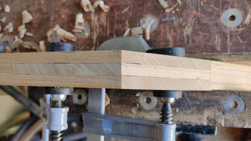
The last job was to clamp it together (again I'm not bothering with glue as this is just a test piece) and plane the two edges:

2025-03-30-19-clamped-and-planed_800.jpg


This is a composite image showing the two faces, which still have quite sizeable gaps unfortunately.

2025-03-30-20-still-gappy_800.jpg


I think I'll have a pause from bridle joints and do some more stock preparation (hand planing mostly) as I've used two of my edge boards up as practice pieces and now need to replace them. I need to have a serious think about what I need to do differently to cut a good bridle joint (or give up and do some other sort of joinery!). I don't think I've made my life easy by doing my first bridle joints at an angle and with a very large (too big for the stretch of the router plane) surface area.
 
Usually I don't like revived old threads, but in this you get a Thank You, it gives me the opportunity to see a picture my friend Brian, helping me to glue up. I miss him. And I've had a message this week to say that his wife Mary, a wonderful lady, has dementia. Later life can be cruel.

Dr Al, all your bandsaw travails would be solved with the Ultimate Bandsaw Tenon Jig (the bridle joints come for free...)
S
 
I think that your idea of splitting the central rail of the top is a good one, it should make fitting the slats easier, assuming you are going to use fairly short stub tenons.
Although my second attempt was successful and still stands in a garden in Nottingham, it's not a project I would eagerly embark upon again.
So good luck, I look forward to the end result.
S
 
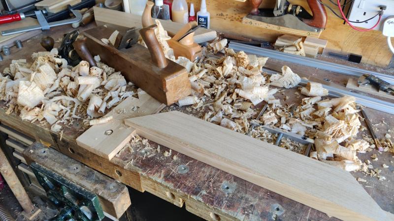
There isn't much to say for this afternoon's activities (partly because some of the afternoon was spent with a glass of cider in the sunshine in the garden!), but I've now got two replacement boards to make up for the two that were used for bridle joint practice. A few photos of the process and the tools used:

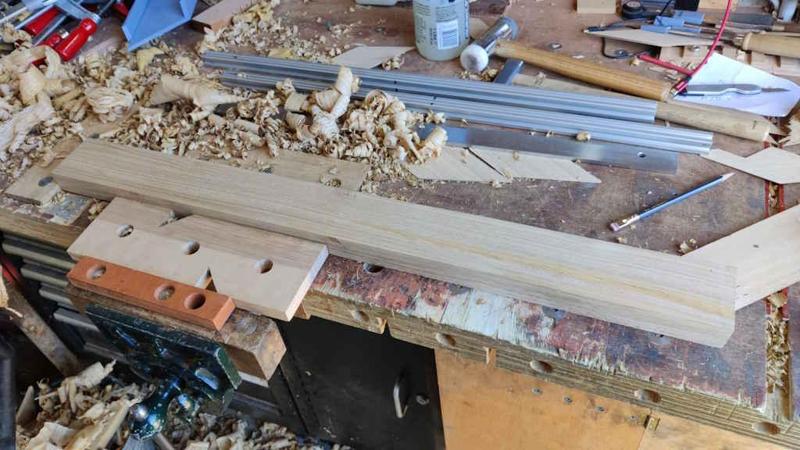
2025-03-30-21-new-boards_800.jpg


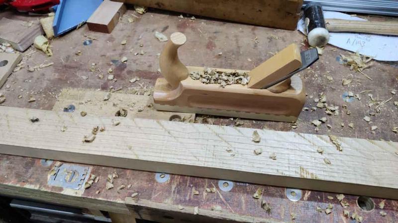
2025-03-30-22-planing-wood-plane_800.jpg


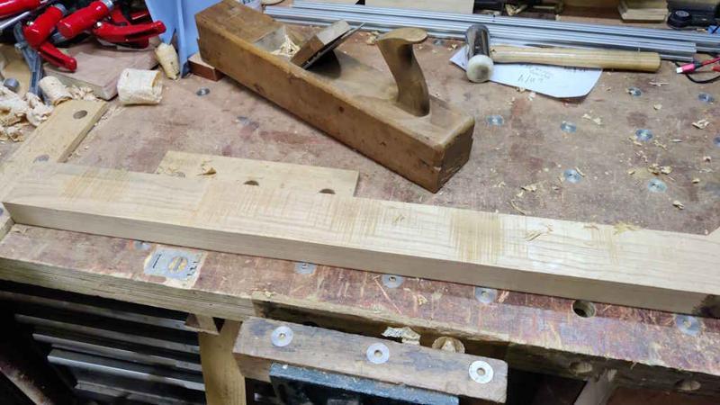
2025-03-30-23-more-planing_800.jpg


2025-03-30-25-shavings_800.jpg


2025-03-30-26-shavings-2_800.jpg


2025-03-30-27-edge-planing_800.jpg
 
Ah, I missed your 4 o'clock post and only saw the 7 o'clock one.

I'll just add that, if you do want to level the tenon part with a router, there are a couple of things that might help.

One is to extend the effective length of the router by adding an extra wooden base. This needs to be thin, but stiff. A bit of ash or chestnut would be ideal.

The other is to line up a bit of the full thickness stock beside the end of the tenon so that the router is supported at both ends.
 
Just thought I'd mention, since you're tooled up in the metalworking department...

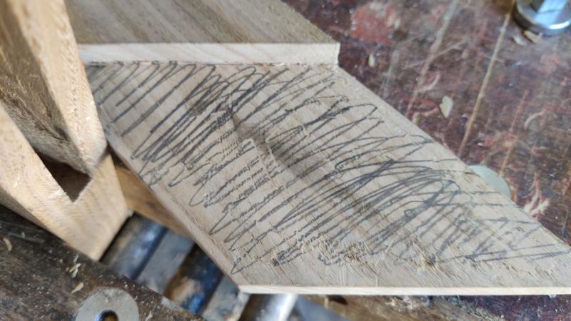
I find using a plate of aluminium with some graphite scribbled on works great for paring walls,
though if you had some cast iron, it probably would be far better, since the graphite would remain,
instead of having to load it on constantly. (an artists stick what resembles a large allen key being neseccaury for ali)
use sparingly if using cast iron, as it would be likely messy if not, though a pencil would do the trick there instead.

Another thing I find, a marking gauge leaves the edges very delicate and tending to chip.
Likely quite slow work compared to other methods... (as seen underneath), but sureworthy all the same,
as you can sneak up on the fit, until the gap between plate and mortise wall disappears.

Enjoying the thread Al

SAM_3900.JPG
 
bridal joints really are tricky to do by hand, I'd argue probably the hardest joint of them all, it's a real test of sawing skills
 
You planely enjoyed your afternoon! :)

Groan. But yes, it was very pleasant. Sweet chestnut is a lovely wood to work with and I really enjoy planing, especially when the weather's good enough that I can have the garage door open. It isn't quite as wonderful to work with as American Black Walnut but it's definitely up there.

I think its your pairing that's causing the gaps, be brave and cut to the line.

That sounds scary! Watch this space...

Ah, I missed your 4 o'clock post and only saw the 7 o'clock one.

I'll just add that, if you do want to level the tenon part with a router, there are a couple of things that might help.

One is to extend the effective length of the router by adding an extra wooden base. This needs to be thin, but stiff. A bit of ash or chestnut would be ideal.

The other is to line up a bit of the full thickness stock beside the end of the tenon so that the router is supported at both ends.

Thanks Andy.

Just thought I'd mention, since you're tooled up in the metalworking department...

I find using a plate of aluminium with some graphite scribbled on works great for paring walls,
though if you had some cast iron, it probably would be far better, since the graphite would remain,
instead of having to load it on constantly. (an artists stick what resembles a large allen key being neseccaury for ali)
use sparingly if using cast iron, as it would be likely messy if not, though a pencil would do the trick there instead.

Another thing I find, a marking gauge leaves the edges very delicate and tending to chip.
Likely quite slow work compared to other methods... (as seen underneath), but sureworthy all the same,
as you can sneak up on the fit, until the gap between plate and mortise wall disappears.

Enjoying the thread Al

View attachment 32729

That's a great tip, thank you.

bridal joints really are tricky to do by hand, I'd argue probably the hardest joint of them all, it's a real test of sawing skills

I'm glad you think so too! "Bridal" joints sounds like it could be something a bit different to what I'm aiming for though 🤣 😜 (sorry, couldn't resist)
 
bridal joints really are tricky to do by hand, I'd argue probably the hardest joint of them all, it's a real test of sawing skills

Window frames I made years ago were done with bridal joints (easy once I got my mindset right) , cut using the radial arm saw (blade swings from vertical to horizontal) and joined with epoxy glue and dowels, exposure to rain minimal. The rebate for the glass was routed first.
 
After a thoroughly enjoyable little "side-quest" on Sunday afternoon preparing some more blanks for the edge pieces, I needed to make a decision on what to do about the troublesome joinery. I could ditch the idea of bridle joints completely (which would make my life a lot easier) or I could sacrifice some more bits of wood and keep practising.

I'd wondered about having a go at some simpler versions of the joint (with the boards joining at 90° and with narrower boards and hence a much smaller lap area), but at the end of the day I'm going to have to master the joint in the big and angled form if I'm going to use it on the table.

Looking at the remains of the two boards that I've been practising with, I realised that there was **just** enough material left to have one more go. Workholding might be a bit awkward, but I can possibly manage if I put a bit of scrap in the gap from a previous attempt.

I felt it was important that I work in a slightly different way this time (what with the previous attempts not working) so the first thing I did differently this time was to shoot the ends at the correct angle as the first operation:

2025-04-01-01-shooting-ends_800.jpg


That's not a big change (or much work), but it means that the knife marks I make on the end grain will be in the right place when the joint goes together. Leaving a few millimetres overhanging as I did on the previous attempts means I have to pair (or saw) very accurately for at least the first few millimetres.

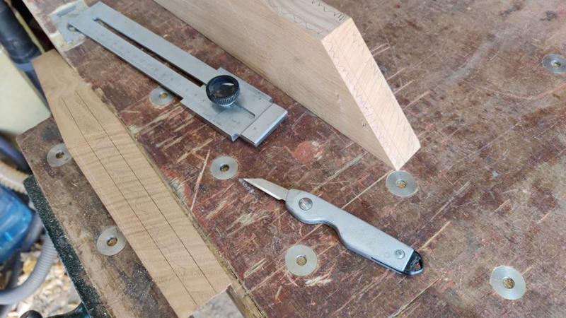
I used a different approach to marking this time as well, using my edge gauge marking thing and a knife:

2025-04-01-02-edge-gauge_800.jpg


This can obviously only be used for one setting at a time (as I only have one of them), but that's fine as I can mark one edge on all (both in this case) of the boards at the same time and then move onto the other edge. The advantage of it is that it gives a lot more control while not slowing down the process much (as long as the board can be clamped as you need two hands). The knife gets pressed against the side of the gauge and then both are moved along the board together, resulting in a line getting cut.

I find it a lot easier to mark different depths of cut using this method than I do with a marking gauge. On the side (different on each board) where the waste was on the free side of the gauge, I used the knife to make a fairly deep line. On the side where the waste was hidden under the gauge (and hence I was cutting on the "keep" side of the line), I marked a very faint knife line:

2025-04-01-03-light-and-dark-line_800.jpg


I could then remove the gauge and deepen the faint line but with the bevel hanging over the waste side.

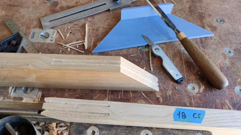
The next change to the process was to cut some "knife walls" with a chisel (and, in some places, an extra pass with the knife):

2025-04-01-04-chiselling-knife-wall_800.jpg


These knife walls result in the knife marked position being quite deep in the boards, but with the chiselled bit being on the waste side:

2025-04-01-05-knife-walls-in-both-parts_800.jpg


The knife wall serves two purposes. Firstly, if I'm brave enough to saw to the line, the knife wall guides the saw as it starts. Secondly (and arguably more importantly), it means that I have a well-defined edge and any paring away that happens starts safely inside the line and hopefully doesn't have a negative effect on what the closed joint looks like.

For the first saw cut (down one of the sides of the socket), I decided to be brave and try sawing to the line (with the knife wall hopefully helping me saw in the right place):

2025-04-02-01-sawing-to-line_800.jpg


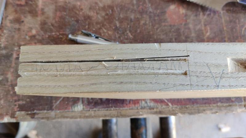
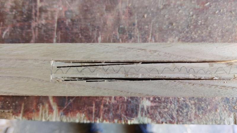
That seemed to go mostly okay, but on the third saw cut (where I tried to remove the triangle left by the two cuts following the three knife walls), the saw wandered at the end of the cut on the side that I couldn't see while sawing:

2025-04-02-02-wandering-saw-cut_800.jpg


It's not the end of the world as there are a couple of mitigating factors here: firstly this is only a practice piece, but also that face will be hidden inside the joint (hence choosing it as the one I wouldn't be able to see when doing that final cut), so the damage should be hidden when the joint goes together.

Nevertheless, I decided to saw away from the line when cutting the other side of the socket:

2025-04-02-03-sawn-away-from-line_800.jpg


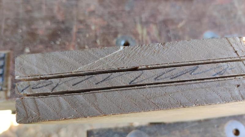
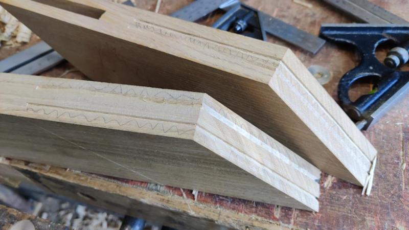
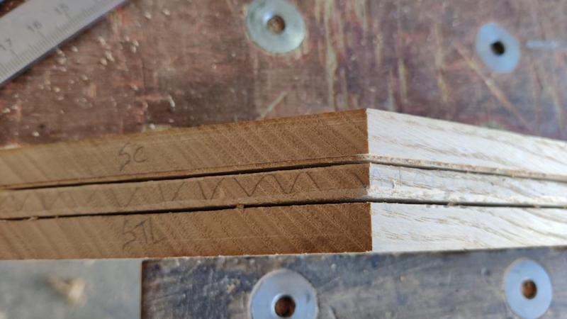
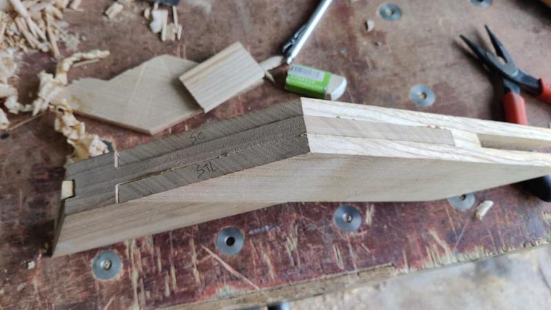
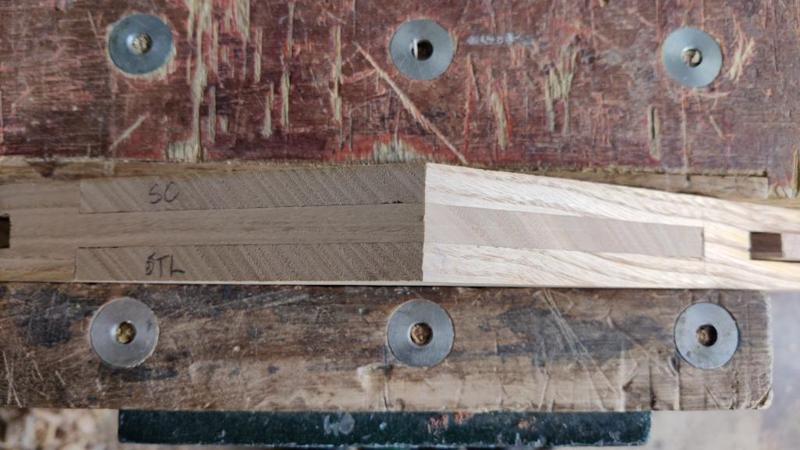
You'll notice in that image that I've also marked the two sides as "STL" for "sawn to line" and "SC" for "sawn clear [of the line]". That was so that I could inspect the resulting joins after assembly and see which one produced a better result.

The hidden face also gained a wandering saw kerf on that third cut, but this time it wandered into the waste:

2025-04-02-04-also-wandered-but-okay_800.jpg


The next job was to pare away the waste in the socket. Through blind luck careful planning (ahem), the side that I'd sawn away from the line (and hence which had more material to remove) was also the side that had the grain direction oriented such that paring from the end was nice and easy. That does of course mean that the comparison between the "to line" and "clear of the line" faces isn't entirely fair.

2025-04-02-05-pared-inside_800.jpg


A bit of paring needed to be done on the other face, despite having tried to saw right on the line, but the amount of paring was minimal.

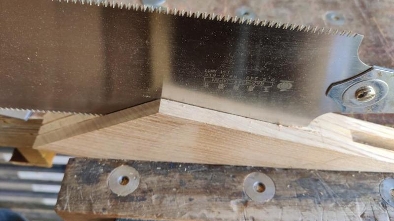
The cheeks of the tenon were sawn off in much the same way as before, keeping a millimetre or so clear of the lines and using the Ryoba for the rip cuts and the cross-cut Dozuki for the cross-cuts:

2025-04-02-06-sawn-off-cheek_800.jpg


To remove the waste in between the knife walls, I decided to just do it by paring rather than trying to use a shoulder, rebate or router plane. I figured it was good practice with the chisel if nothing else. One side had to be pared from the end in and the other from the shoulder out, but in this case the 45° angle helped as for the outward paring I could start at the acute angled point (top-right of the photo below) and easily work out.
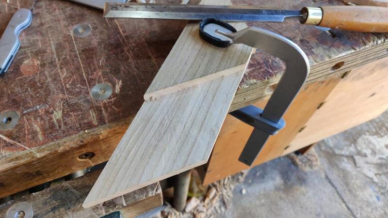
2025-04-02-07-paring-cheek_800.jpg


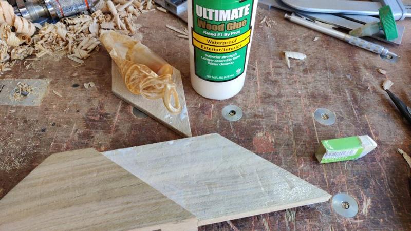
Given that there was definitely not enough material left to use this test piece for another attempt (there's only about 20 mm of solid wood between the previous joint attempt and this one), I figured I might as well glue the joint together and see how it will look "for real" rather than just clamping the faces together and planing them. I dug out my old bottle of waterproof glue (as this will be an outdoor project in the end and I might as well do the tests with the same glue), dug out the rather impressive crust that had formed over the sides of the bottle (you can see the removed crust sitting on the off-cut to the left of the bottle in the next photo) and applied glue with a brush to both big faces of the tenon and both big faces of the socket:

2025-04-02-08-glue-and-crust_800.jpg


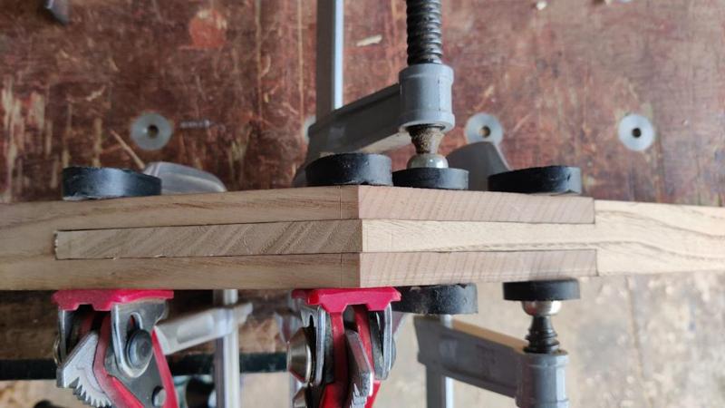
I then did the normal thing of throwing as many clamps as I could fit onto the joint:

2025-04-02-09-clamped_800.jpg


It came out of the clamps today and this is what it looked like:

2025-04-04-01-out-of-the-clamps_800.jpg


Holding it for planing the faces was rather awkward given how small the pieces are and how they've got great big slots cut in the ends from previous attempts, but I managed to get there (using a 50° blade in a bevel-up plane giving a 62° cutting angle as the grains were opposing on the two pieces). The face side looked okay to me (if you ignore the dirty mark from where I clamped it in the vice afterwards to plane the edge - note to self: clean your vice!)

2025-04-04-02-planed-face-side_800.jpg


For convenience I used the same high angle plane to do the edges and then I remarked the sawn-to-line and sawn-clear sides:

2025-04-04-03-planed-edge_800.jpg


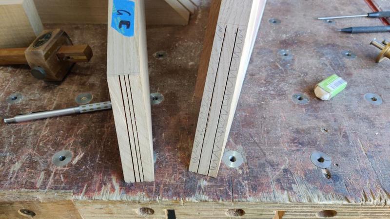
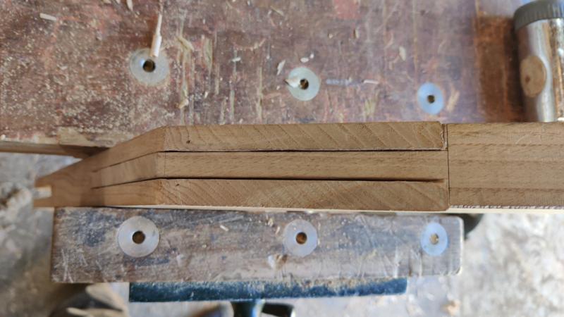
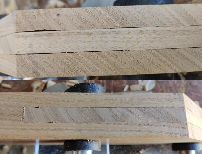
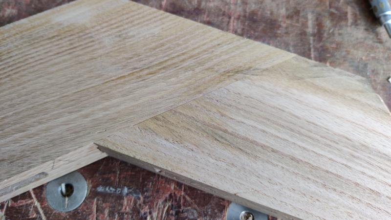
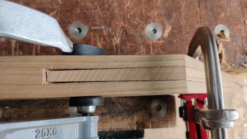
That is miles better than my previous attempts so I'm really pleased with that. It's not perfect, especially down in the corner...

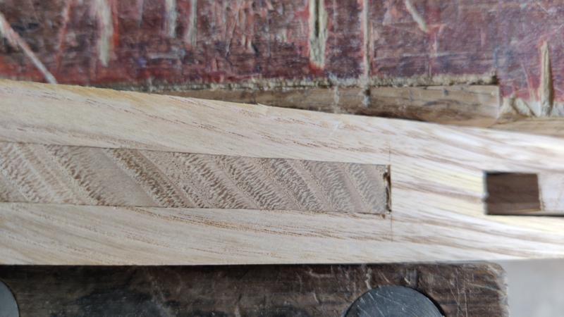
2025-04-04-04-planed-edge-corner_800.jpg


... but that should be easy enough to deal with if it happens on any of the real parts. I'm pretty sure the reason for that is bad marking up: it's a little awkward ensuring that the two shoulder lines on either side of the tenon piece are along the same line and I got it a bit wrong this time, as you can see by the shoulder line on the non-face side:

2025-04-04-05-planed-underside_800.jpg


Nevertheless, that's fairly easy to sort out (I already have a simple plan for doing that better in future).

Overall, it feels like the knife wall thing makes enough of a difference for bridle joints to be viable. As for sawing to the line, I'm a little on the fence at the moment but I'll ponder it over the next few days (as I won't have much workshop time for a while). The "sawn clear" side looks marginally better than the "sawn-to-line" side, but there's not much in it. For the tenons, I'll definitely saw clear (as I did on both parts of this test piece) as it's relatively easy (and quite enjoyable) to clear up the excess with a chisel. For the sockets it's quite a lot quicker (and quite a lot less hassle) to saw to the line so I can see an advantage there. Knowing that the third face will be hidden in the joint also gives me a bit more confidence as I can see the other two faces clearly when doing the two saw cuts that could affect them.
 
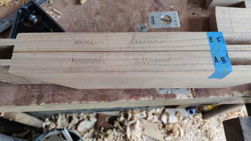
During a few evenings this week, I spent a bit of time preparing the rim planks, including the new two. The first thing I did was plane all of the faces and edges again to remove all the knife lines I put in the wrong place a week or so ago. I then re-labelled them all, with the labels on the inner edge this time so I can use the outside edge as the reference edge without the tape getting in the way.

2025-04-11-01-new-set-of-planks_800.jpg


To keep things as simple as possible, I also shot all the planks down to the same length and with a nice clean 45° angle on the end:

2025-04-11-02-shooting-45_800.jpg


That gave me a little pile of planks, all exactly the same length (which should help produce a regular octagon rather than a wonky one) and approximately the same thickness and width (but with up to a millimetre variation as I didn't think it was that critical at this point).

2025-04-11-03-all-the-same-length_800.jpg


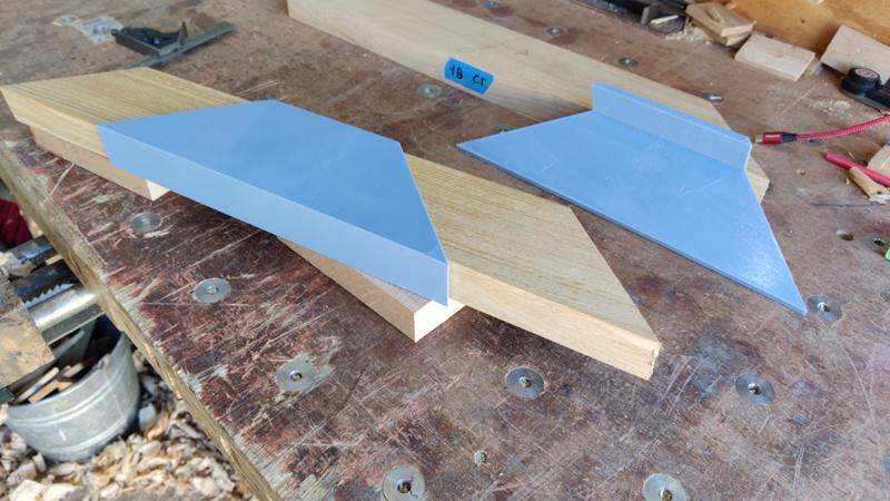
I (well, the 3D-printer) had made a gauge to help mark these long mitres and ensure that when I go round the corner (on both sides) I'm in exactly the right place, so I used that on the first board...

2025-04-11-04-3d-printed-gauge_800.jpg


... and then used the other similar one to transfer the mitre lines down onto the other edge:

2025-04-11-05-second-gauge_800.jpg


As on the last attempt, I used my edge distance gauge thing (referenced off the face side) to mark the thickness of the bridle joint. This time I didn't bother doing just a light mark on the side where the waste was under the gauge (and deepening it when the gauge was removed), I just trusted in the fact that the knife has a thin blade and it'd probably be okay.

2025-04-11-06-edge-distance-gauge_800.jpg


Knife walls were prepared as before:

2025-04-11-07-knife-walls_800.jpg


On the socket piece, I sawed straight to the line:

2025-04-11-08-sawing-to-line_800.jpg


As before, on the edge I can't see when doing the third cut, the saw wandered a little bit (but it's not the end of the world as that edge will be hidden inside the joint):

2025-04-11-09-saw-wandering-on-hidden-side_800.jpg


On the tenon, I sawed away from the line and pared to fit. Paring to fit took a long time as I had to keep tweaking things. When it finally went together as well as I thought it was ever going to, I put some clamps on it and took this photo:

2025-04-11-10-far-from-perfect_800.jpg


It's far from perfect, but I think I'm going to call it good enough. It'll end up being a very expensive table if I keep having to make new planks to replace each pair after every attempt at a bridle joint!

I'm still not really happy with the process of cutting the joint. It took me most of the afternoon to cut a single bridle joint and even then it wasn't that good. I'm tempted to have another go with the bandsaw for the rip cuts: if I can get that cutting accurately enough then it'd hopefully not require as much time spent paring and tweaking. The risk is, of course, that I give myself a very quick and efficient method of creating more firewood!

I'm beginning to regret learning how to cut bridle joints on a 45° angle and with such a big mating area. Now which woodworking cricketer had the bright idea of using bridle joints on this table? You can really go off people you know... ;)
 
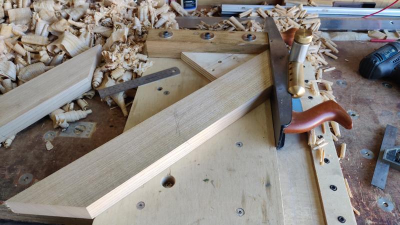
Following the attempt described in the last post, I decided to go back to the bandsaw, but to keep the knife walls as a reference and to pare with chisels and router plane as appropriate.

I used the same jig as seen earlier (although it's gained a little fence on the side now, purely to move the workpieces out a bit so the saw blade won't be going anywhere near the nails holding the jig together).

2025-04-13-01-knife-walls-on-bandsaw-jig_800.jpg


I sawed fairly close to the line (and in one case, too close to the line):

2025-04-13-02-bandsawing-close-to-line_800.jpg


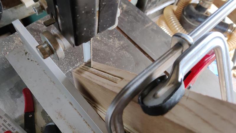
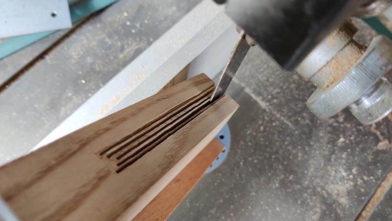
While on the bandsaw, I decided to chop the waste on the socket into little slivers to make it nice and easy to remove:

2025-04-13-03-hogging-out-waste_800.jpg


There was then lots of paring of sockets:

2025-04-13-04-lots-of-paring_800.jpg


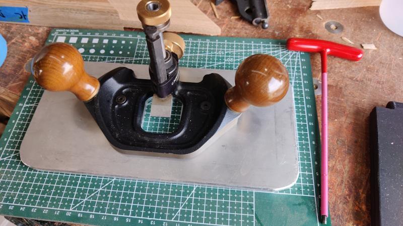
In a short aside, I rummaged in my drawer of aluminium bits and bobs and found this plate:

2025-04-13-05-aluminium-plate_800.jpg


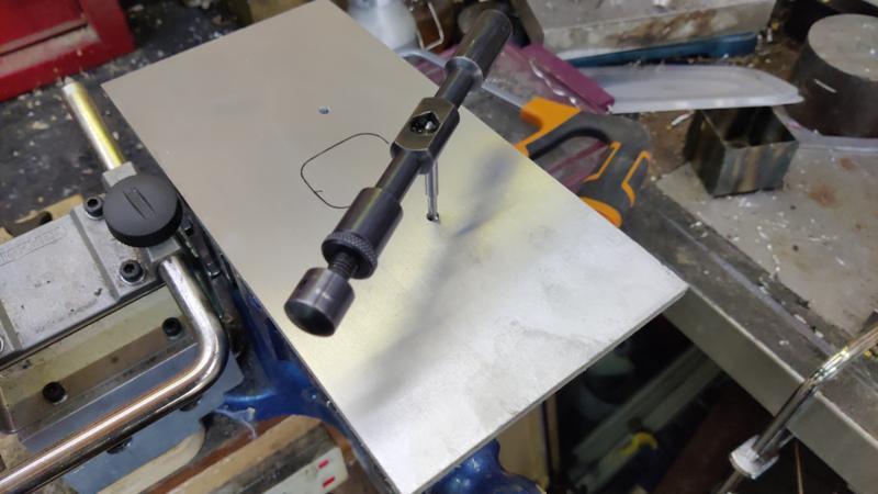
After marking it up, I drilled and tapped a couple of M5 holes:

2025-04-13-06-tapping-holes_800.jpg


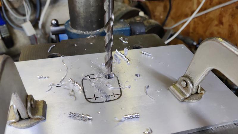
To make the hole in the middle, I started with a small spotting drill, then drilled through 8 mm:

2025-04-13-07-drilling_800.jpg


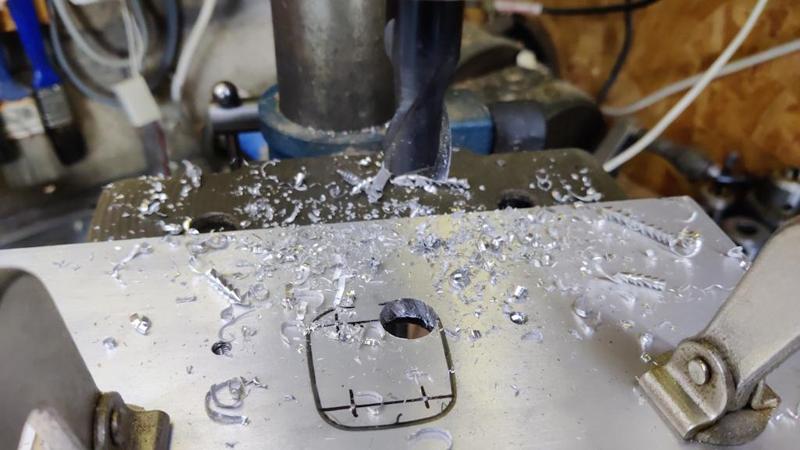
I then drilled through 12 mm (with a spotting drill as it saved moving the pillar drill's table down and losing alignment) and finished off with a 16 mm slot drill. The slot drill isn't really a good tool to use in the pillar drill (it's not especially good for either the slot drill or the pillar drill), but it did the job:

2025-04-13-08-spot-drill_800.jpg


You can see the rough finish you get off the slot drill (on the right) compared to the finish from the 12 mm spotting drill on the left:

2025-04-13-09-spot-drill-rough-finish_800.jpg


If I'd used the milling machine that probably wouldn't have been a problem.
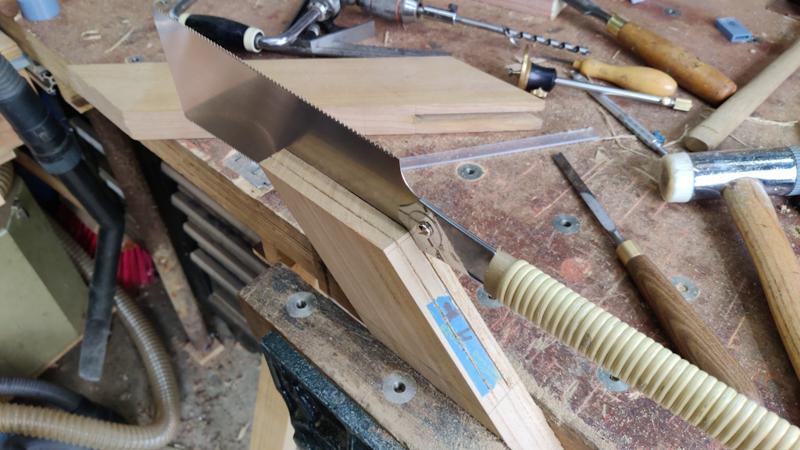
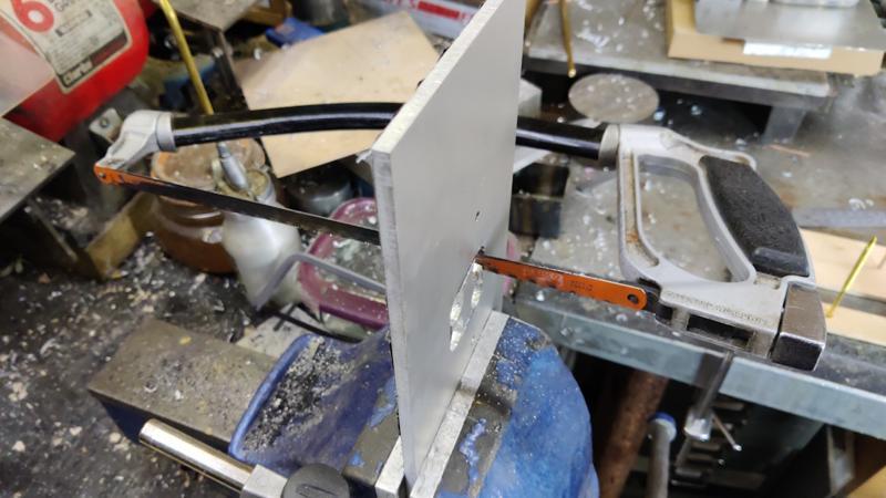
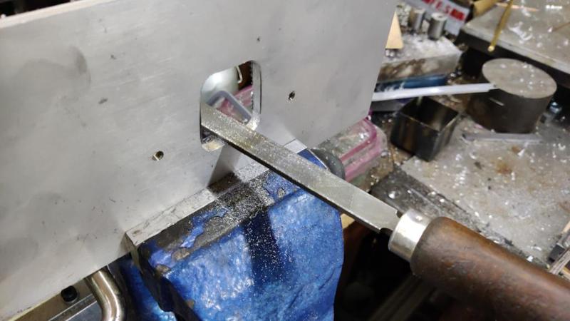
I used my so-called "3D" hacksaw to join the holes together:

2025-04-13-10-hacksawing_800.jpg


There was then an awful lot of filing (and a bit of wondering why I didn't just set up the milling machine and do the job properly!)

2025-04-13-11-filing_800.jpg


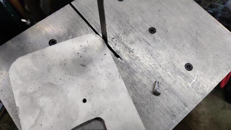
The corners got roughly rounded using the home-made vertical table for my metal-cutting bandsaw:

2025-04-13-12-rounding-corners_800.jpg


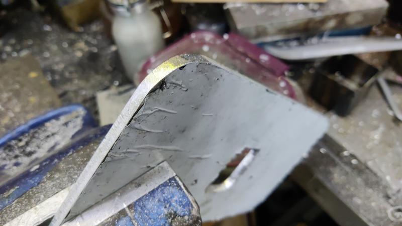
They also got filed:

2025-04-13-13-filed-corners_800.jpg


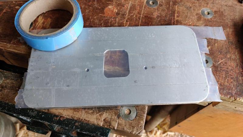
After chamfering all the edges, I laid some strips of UHMW-PE tape across the bottom surface:

2025-04-13-14-uhmw-pe-tape_800.jpg


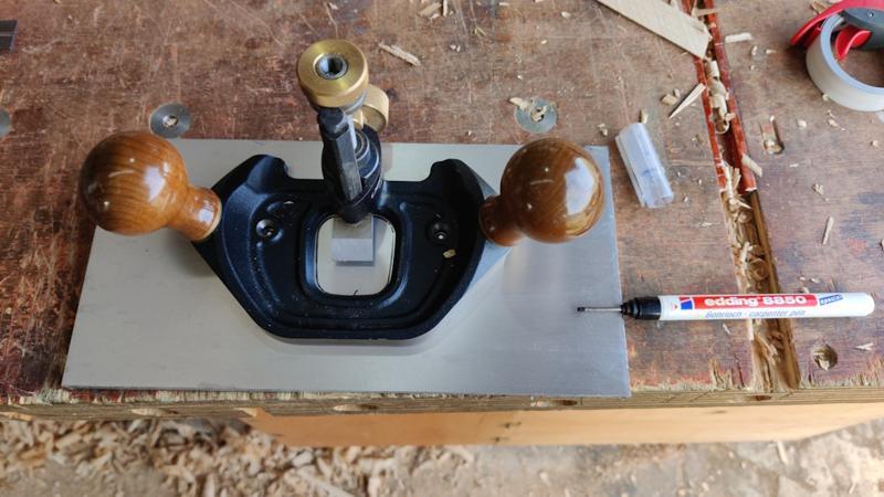
That tape is super slippery, so will allow me to press down hard on the plate (to stop it tipping) but still move it back and forth. It'll also stop any aluminium dust getting on the wood. Once the tape was trimmed to match the shape of the aluminium plate, I could mount the router plane:

2025-04-13-15-trimmed-and-mounted_800.jpg


It works very well:

2025-04-13-16-router-plane-tenon_800.jpg


It doesn't have quite enough reach to get to the very tip of the tenon, but it gets close enough to make it easy to sort the rest out with a chisel. I had wondered about making the plate lop-sided: i.e. mount the router plane at one end so that there's a lot more support hanging out but only one side. The disadvantage of that would have been that it's quite useful to be able to attack in different directions and to be able to do so would require the ability to mount the router plane in either orientation and would also mean that I was constantly mounting and dismounting it. I figured it would be more pleasant to use if I just accepted that it couldn't go all the way to the tip.

The first joint that was cut on the bandsaw and then finished with chisels and router plane looked good (and took about an hour and a half to cut in total, including marking up, sawing, paring and final tweaking to fit):

2025-04-13-17-first-bandsaw-router-joint_800.jpg


I mentioned earlier that I messed up one of them on the bandsaw cut. This is what it looked like when fitted:

2025-04-13-18-worst-joint_800.jpg


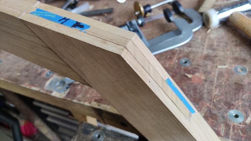
I didn't pay enough attention to making sure the jig was standing upright and the saw was cutting in the right place at the bottom of the joint (which isn't easy to see while cutting). It was the last joint I did in the day and I think I was getting a bit tired; I should have stopped earlier. Hopefully I'll be able to fill that gap in. Worst case I think I can get away with just remaking one piece (the one with the tenon here), although that would mean cutting a socket to fit the piece that engages at the other end, which isn't ideal (as it's easier to tweak a tenon to fit a socket than vice versa).

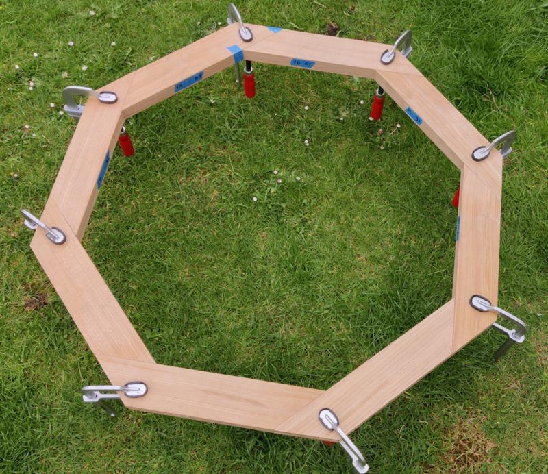
Nevertheless, over the course of the last couple of days, I've worked my way through all the pieces and it was quite satisfying to put them all together for a trial assembly:

2025-04-13-19-eight-joints-done_800.jpg


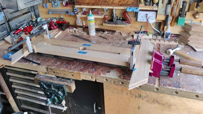
The next job will be to prepare the wood for the two long cross bars and then to cut the mortice and tenon joints that will hold them in place.
 
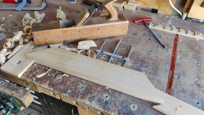
I haven't had a lot of time since the last post, but I have had the odd evening of wood preparation and I've managed to spend a decent amount of time on the table today. The evenings of wood preparation involved a bit of scrub-planing...

2025-04-20-01-scrubbing-cross-bars_800.jpg


... and quite a lot of roughing out...

2025-04-20-02-roughing-out-cross-bars_800.jpg


... and then finishing off with a smoothing plane to give some planks for the cross bars:

2025-04-20-03-planed-plank_800.jpg


I also planed the edges square with a #7, but didn't take any photos of that (there are plenty of them elsewhere on this thread though!). After finishing the second cross bar, I dropped my plane on it and made a sizeable dent in the middle. Much swearing ensued. I considered chopping the piece in half and using it elsewhere, but I decided to try steaming it with an iron and see what it looked like. After a couple of goes with a damp tea towel and a hot iron, it looked like this (pencil marks added by me to show the affected area before and after steaming):

2025-04-20-04-dent_800.jpg


That was a lot better than the "before" photo (which I didn't take so you'll have to imagine it). It's still not ideal, but it occurred to me that it was conveniently right in the middle of the plank and close to an edge, so I can use that location for where the parasol hole will be drilled and hopefully the dent will disappear completely.

While I was planing, I decided to make another rim plank to replace the one with the shoddy joinery shown in the previous post. Here it is next to the one it will replace...

2025-04-20-05-new-rim-plank_800.jpg


... and here it is with the joints on both ends cut and pared to fit:

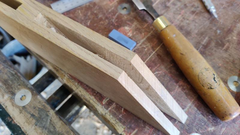
2025-04-20-06-fitted-both-ends_800.jpg


The process was the same as before so I didn't bother taking any photos. I'm much happier with that than with the other one. The only downside is the grain direction on the face is different, so that means there will be even more grain direction changes around the rim. Hopefully if I just plane it with a high angle plane it'll come out okay, but worst case I'll resort to a card scraper, cabinet scraper or scraper plane (anything but sandpaper!)
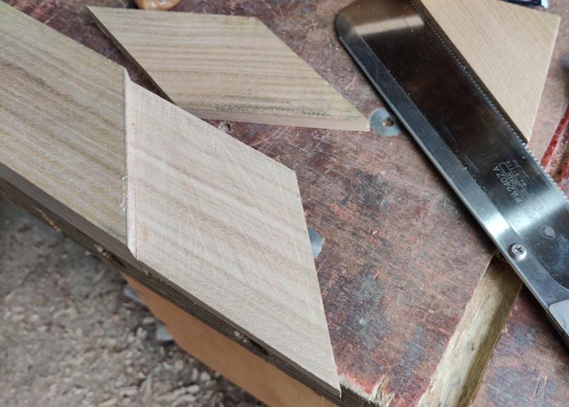
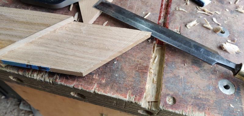
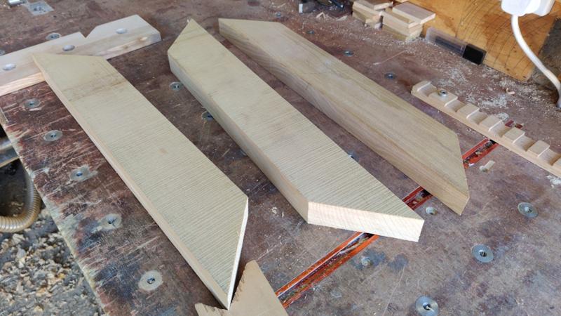
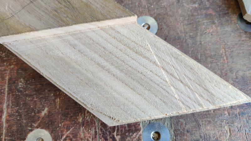
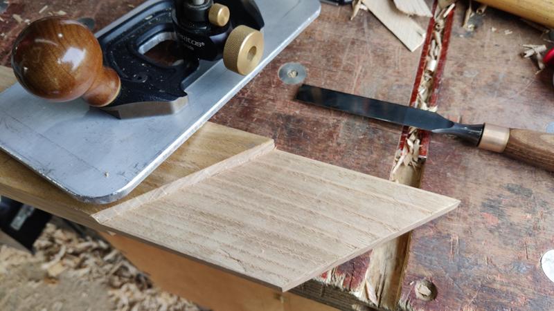
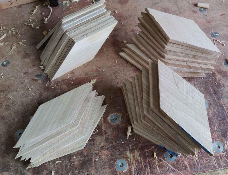
Does anyone have an urgent need for a lot of sweet chestnut parallelograms?!

2025-04-20-07-parallelograms_800.jpg


The grain on the two cross bar planks I prepared are quite different from one another, but it would be very wasteful of wood to try to get a perfect match so I decided not to worry about it. With a few years of sitting outside, they'll all fade to grey anyway. Here are the two cross bars positioned with the corresponding rim planks to give an idea of how they'll (hopefully) go together:
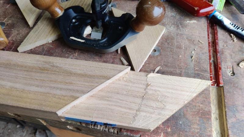
2025-04-20-08-different-grain_800.jpg


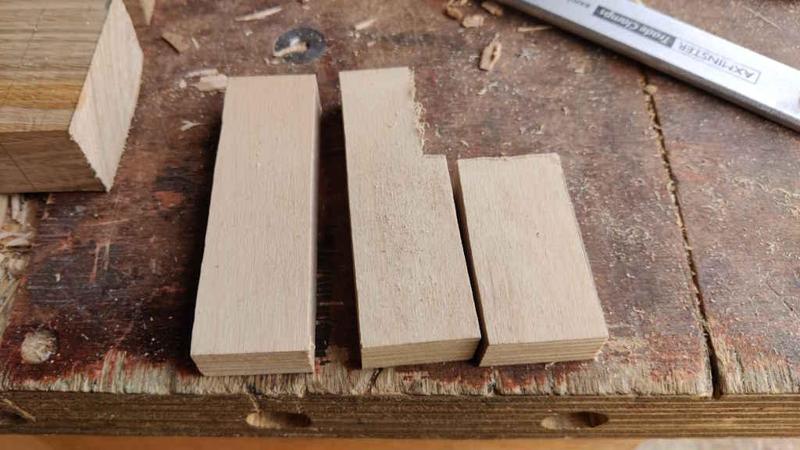
I rummaged around and found a little off-cut of 18 mm plywood. That got chopped into three pieces:

2025-04-20-09-chopped-up-plywood_800.jpg


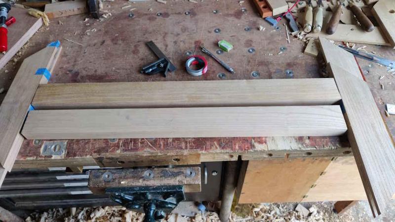
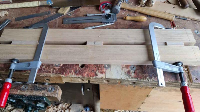
The pieces then got clamped in between the two cross-bars and a centre point marked:

2025-04-20-10-shoulder-marked-and-plywood-clamped_800.jpg


You can also see in that photo that I've marked the position of the shoulder line (I think it was just in pencil for that photo, but I've since gone round with a knife). The distance between the two centre lines was based on a measurement I took when the frame was assembled (but has since been taken apart). Ideally it would probably be based on holding the bars up to the assembled frame, but with so little space in the workshop, I was quite keen to dismantle the rim frame as soon as possible so I decided to just risk working off a measured dimension.

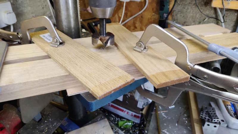
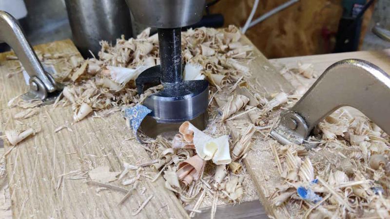
The clamped-together bars were taken over to the pillar drill, placed on a sacrificial bit of scrap plywood and clamped in place with some C-clamps (my preferred option for pillar drill work as they're so quick to fit):

2025-04-20-11-big-forstner-and-c-clamps_800.jpg


A 50 mm Forstner then worked its way through the middle; I stopped when I saw bits of plywood coming out:

2025-04-20-12-forstner-drilled_800.jpg


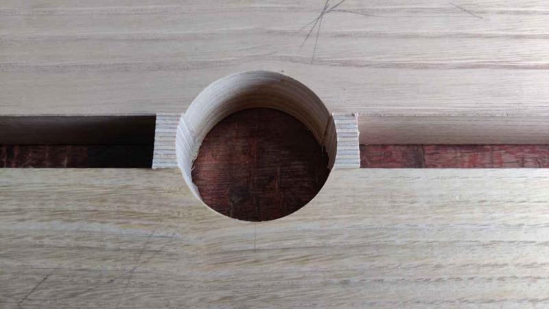
That's given me a fairly neat (and very oversize) hole for the parasol shaft to come up through. I had been planning to do a somewhat smaller hole, but decided to go with my biggest decent quality Forstner bit as it gave the best chance of getting rid of that dent from when I dropped the plane.

2025-04-20-13-parasol-hole_800.jpg


The next job was to decided where the mortices were going to go. I decided to have a 10 mm-ish shoulder all round on the tenon (leaving a 10 mm by 50 mm tenon). With the cross bars still clamped together, I could take some measurements of where the tenons would be relative to the centre line and then mark those positions on the two rim planks:

2025-04-20-14-positioning-of-mortices_800.jpg


The width of the tenons was marked using a pair of marking gauges, one for each line:

2025-04-20-15-marked-out-with-two-gauges_800.jpg


As is my current preferred practice, I'm going to use a smaller mortice chisel than the size of the hole that I'm aiming for:

2025-04-20-16-smaller-mortice-chisel_800.jpg


I do have a 10 mm mortice chisel, which would cut the mortice to size, but I don't really see the benefit of doing so. Paring an undersize mortice only takes about 30 seconds or so. Working to the size of the mortice chisel means I have to be a lot more careful when chopping the mortice (to make sure the chisel doesn't twist at all) and that means that the chopping bit of cutting the mortice takes a bit longer, so overall the total time ends up being about the same.

Paring is just a case of dropping a bench chisel into the marking gauge lines and pushing down (hand force is plenty):

2025-04-20-17-paring_800.jpg


As well as allowing me to do the chopping bit of the mortice preparation a lot quicker (as I don't have to pay as much attention), the chop-small-and-pare method leaves a lovely finish on the glue surface of the mortice:

2025-04-20-18-clean-pared-edge_800.jpg


I'd be interested to hear if anyone can explain any other reasons I'm missing why working to the size of the mortice chisel is better. I know it's the recommended method in a lot of books I've read, but there's no explanation of why it's recommended and given it doesn't seem to save any time I'm struggling to understand the benefit.

Anyway, in not very long at all, I've got four mortices chopped and paired:

2025-04-20-19-all-mortices-done_800.jpg


I'll cut the tenons to match tomorrow and then I think I'll be pretty much ready to glue these bits together (although I might go round all the bridle joints again and just check whether any would benefit from a bit of tweaking).
 
Cutting the tenons was a fairly quick process. After marking the thickness with the two gauges I used yesterday, it was just a case of lots more sawing and paring. For the first one, I sawed a little way away from the line:

2025-04-21-01-sawing-away-from-line_800.jpg


I also sawed away from the line on the shoulder, so I had to pare both the shoulder and the face, but that was pretty quick:

2025-04-21-02-paring_800.jpg


For the second one, I decided to make a knife wall and try sawing directly to the line:

2025-04-21-03-sawing-to-line-in-knife-wall_800.jpg


That worked okay, but I think the process of creating the knife wall was slower than just cutting a little way from the line and then paring, so I went back to the first method on the other ones. The fit was better on the ones where I cut a little away from the line as well (although the one where I cut to the line was okay).

I didn't take any photos of the 90° saw cuts to remove the ends of the tenons, but you can see the pencil lines in the other photos so I'm sure you can imagine what that entailed. I didn't use knife lines for those (I just cut along the pencil line) as I don't think the position is that critical.

With the tenons cut, I thought it was a good time for a test fit:

2025-04-21-04-test-fit_800.jpg


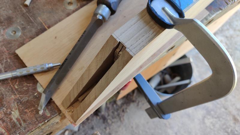
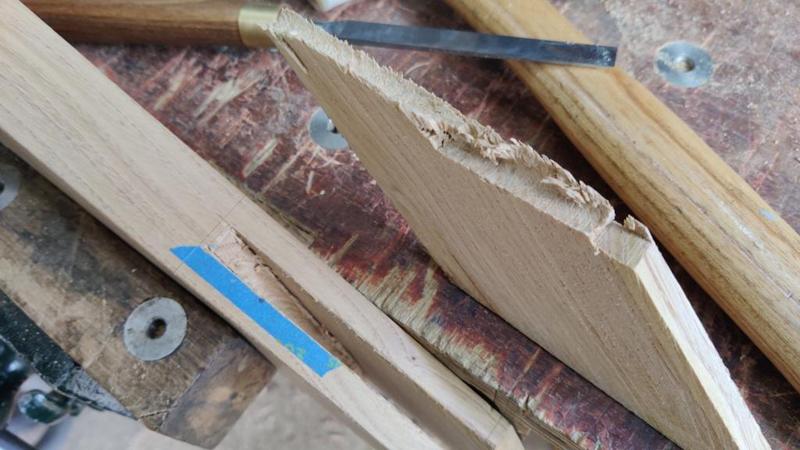
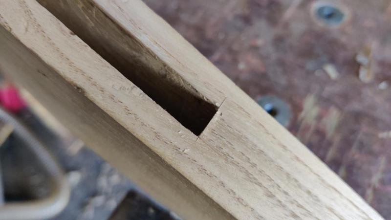
Irritatingly, when I was chiselling the shoulder line on one of the pieces (on the face side), the air compressor pump kicked in and made me jump, resulting in the chisel jumping just as the mallet was coming down. Hopefully I'll be able to fill the little gap in after it's all glued together:

2025-04-21-05-oops_800.jpg


With the mortice and tenons assembled, I thought I might as well push all the bridle joints together as well and see how it's looking:

2025-04-21-06-test-fit_800.jpg


I still want to go back round all those bridle joints and check I'm happy with the fit: I think I got better at gauging how good the joints were as I did more of them so the earlier ones might benefit from a little bit of extra tweaking. With that done I need to make a decision about whether to chamfer all the edges before gluing it together. If chamfering, I also need to decide whether to chamfer the joints (which would make planing the top a heck of a lot easier but might give little channels for water to sit in). The chamfering might also expose any gaps where I've undercut shoulders I guess.

I'd very much welcome any thoughts anyway.

This is what I mean by chamfering the joints:

2025-03-25-03-latest-design-detail_800.jpg
 
By chamfering the joints like that are you not just encouraging somewhere for water to sit?
That's exactly what I was worrying about:

whether to chamfer the joints (which would make planing the top a heck of a lot easier but might give little channels for water to sit in)

It might well be better not to do it. Not doing it will make planing the top much more difficult (having to be careful about blowing edges out when planing near a joint), but as you say, it'll probably be better from a water-protection point of view.
 
Sorry Al, I'm guilty of not reading your posts properly. Maybe this is when powered sanding, random orbital sander, might be a better option than planing if there are slight height differences after glue up. Goes against the hand tool ethos though.
 
Sorry Al, I'm guilty of not reading your posts properly.

No problem, we all do it! The more I think about, the more I think you're right though: the chamfers are just asking for trouble. I still chamfer the bits that aren't in the joints (so there aren't sharp edges).

Maybe this is when powered sanding, random orbital sander, might be a better option than planing if there are slight height differences after glue up.

True, but I loathe sanding so I'd rather do it with plane if possible. I generally prefer the look of a planed finish (on the occasions I do it right!) as well.

Goes against the hand tool ethos though.

I'm not sure I really have a "hand tool ethos", although I definitely gravitate towards them these days. You'll have seen plenty of bandsaw & pillar drill use in this thread. For me, the hand tool thing is a combination of liking learning skills & hating noisy & dusty tools. Sanding is a dust mask & ear defenders type of job and I'd rather avoid them if I can. Planing requires no PPE!
 
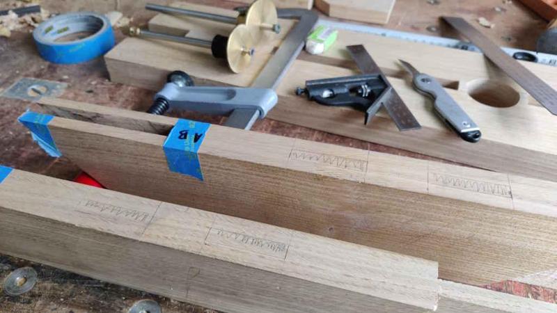
Just before lunch, I'd gone round all the bridle joints once more and was feeling like it was time to glue the frame together. I got everything I could think of I might need together (including those parallelogram bits of sweet chestnut to act as clamping pads):

2025-04-21-07-get-everything-together_800.jpg


I started by gluing the mortice and tenon-joints together and getting them clamped in place. I shoved the bits of plywood from earlier in between them and clamped them together as well as having clamps along the length. The plywood bits will make sure that any gaps along the length of the tenon (which was just marked up with a pencil) won't result in the bars being off-parallel and will also ensure the spacing is right such that the central circle is still circular. Probably unnecessary, but I figured it can't hurt.

2025-04-21-08-glue-mortices_800.jpg


After that, there was a lot of gluing, using more glue in a single glue-up than I ever have before. Each bridle joint got a generous dousing of glue on both the outside surfaces of the tenon (which were easy)...

2025-04-21-09-gluing-bridle_800.jpg


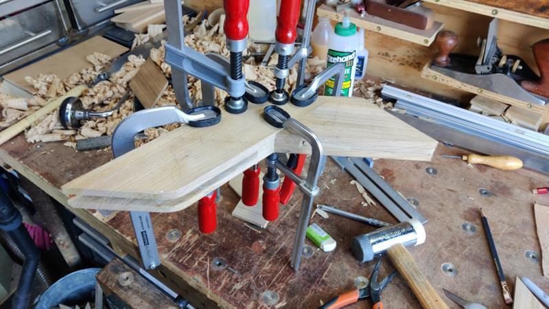
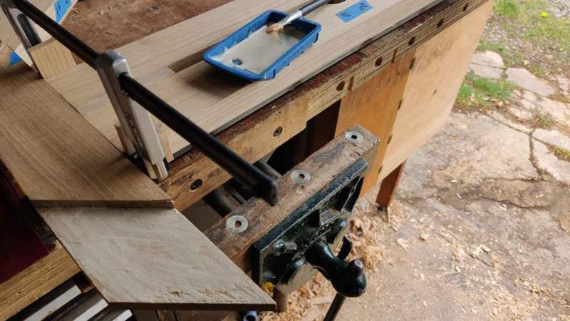
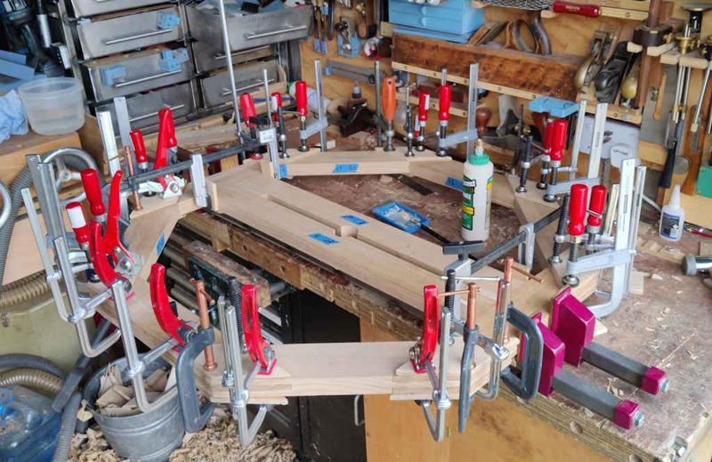
... and the inside surfaces of the socket, which were a bit more awkward and didn't do my (cheap Lidl) paintbrush much good! As each half went together, I put one clamp on each corner of the parallelogram clamping pads (which, conveniently, each had one nice smooth planed surface to press against the table). I suspect that 36 clamps in one go is probably a record for me:

2025-04-21-10-lots-of-clamps_800.jpg


I'll leave that now to dry fully. I could probably un-clamp it all by now (three-ish hours after the glue-up), but I think it's better to just leave it until fully dry. I probably won't get much more time on the project until the next bank holiday in a couple of weeks' time so you'll have to wait until then to see how it came out.

I need to plane the faces and the edges of the assembly, but I'll probably leave that until I've fitted all the slats (which I'm intending to do with dovetail half-lap joints, hence being able to do them after gluing the rest of the frame together). The next job will therefore be lots and lots of planing of rough sawn timber to give me something to use to make those slats.
 
I really like how you got rid of that ding in the centre hole. It's the sort of minor blemish that nags if you don't deal with it. (y)
Thanks Steve. In a lot of ways I was quite lucky: the plank was sufficiently over-length that I could move the shoulder lines sideways (enough to get the ding in the centre) and still have enough left at the ends for some decent tenons. If the ding hadn't been near the edge it also would have been impossible to cover it up.
 
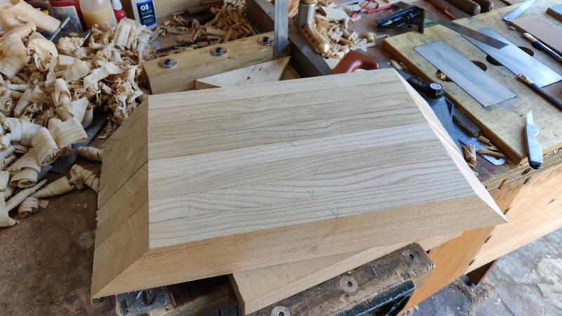
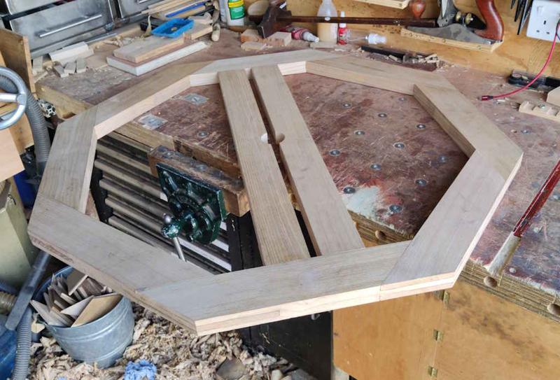
I had a little bit of time this evening and I couldn't resist having a quick look at the table with the clamps removed (removing all the clamps and putting them away took a surprisingly long time!)

2025-04-22-01-out-of-clamps_800.jpg


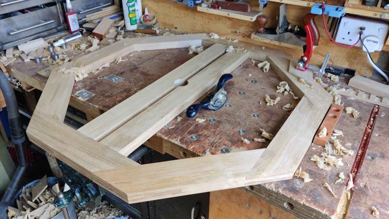
The size of the table-top is extremely conveniently (and by pure coincidence) just right to go between a couple of stops on the bench. That meant that I could place it on the bench top and have it well supported on three sides (two with stops and one with the wall). A single hold-down held it in place firmly enough that I could have a go at cleaning up the top. I started with a 62° angle plane (50° blade in a low-angle smoothing plane) but quickly concluded that the #80 cabinet scraper was the tool for the job. When I do the final clean-up I think I'll need to use a card scraper in some places, but the cabinet scraper worked well for the bulk of the job.

2025-04-22-02-quick-plane-and-scrape_800.jpg


It's far from perfect, but it'll do for now. I also need to deal with the bottom, which I didn't have time for today. That'll involve a bit more aggressive stock removal (with a plane of some sort) as the boards weren't all the same thickness and hence some stick out the back further than others. It's not critical I do that before fitting the intermediate slats (as I'll be referencing off the top surface for any dimensions), but I think it'll make the job a bit easier so I'll probably do that next.
 
Back
Top