Dr.Al
Old Oak
Thanks Scott
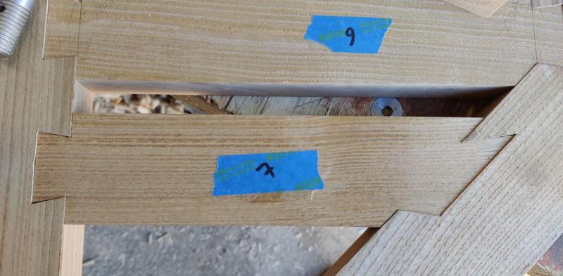
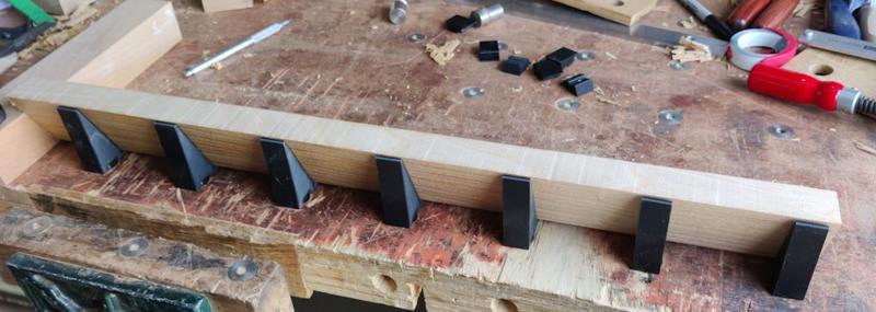
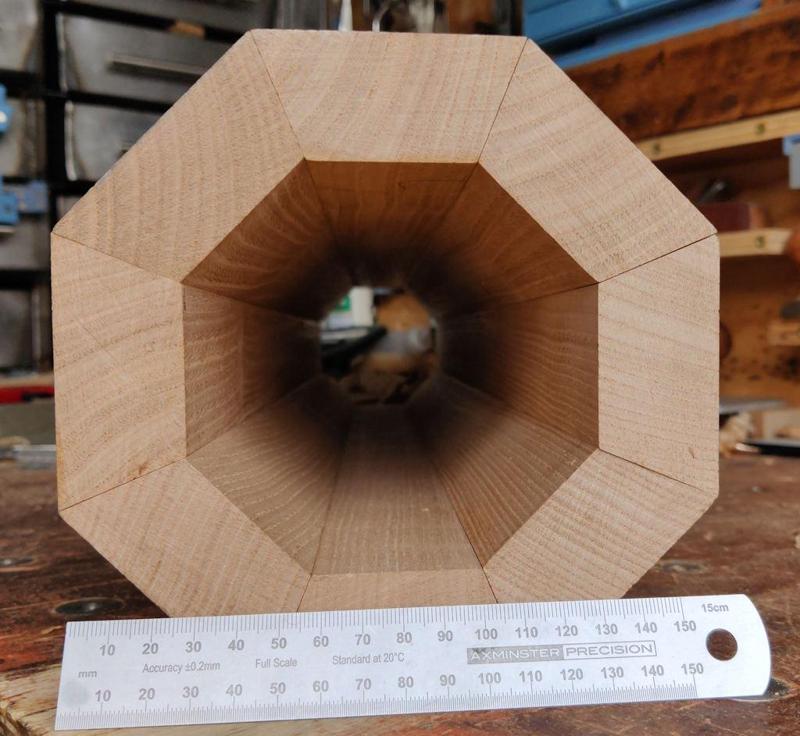
The accuracy and precision of those joints is something to behold but, sorry there is a but, there is no mechanical strength, only the glue holding them in place. If/when the wood moves and the glue detoriates what stops them from just falling out?
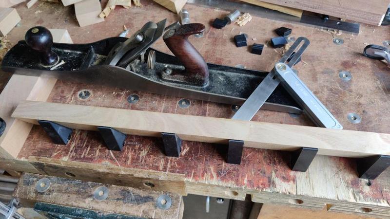
Add a screw up through the dovetail, maybe angled towards the table's perimeter to maximise screw length and downward force resistance, preferably stainless steel. Slainte.It's the same point that Richard made earlier in the thread & it's a fair comment. Too late to do anything about it now though.
Add a screw up through the dovetail, maybe angled towards the table's perimeter to maximise screw length and downward force resistance, preferably stainless steel. Slainte.
Sorry, Al, I've been busy.....
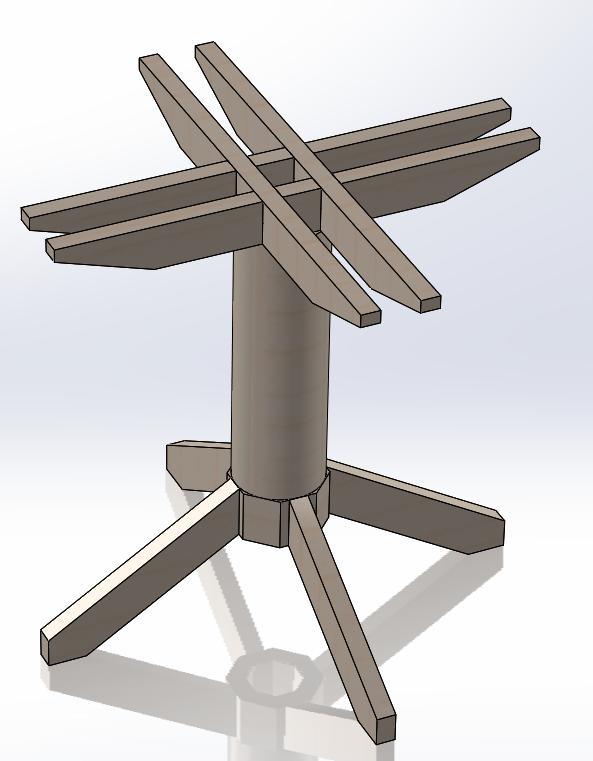
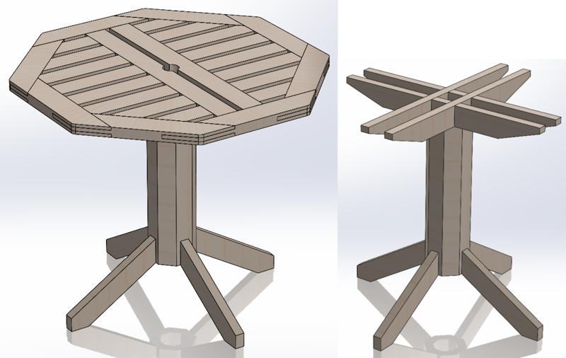
Personally, I'd go for the octagon. The rectilinear feet look a bit incongrous with a cylindrical stem. If you were to shape the legs/ feet in a more traditional manner, then I think the round would be OK......although, again, it might look better shaped/ tapered.
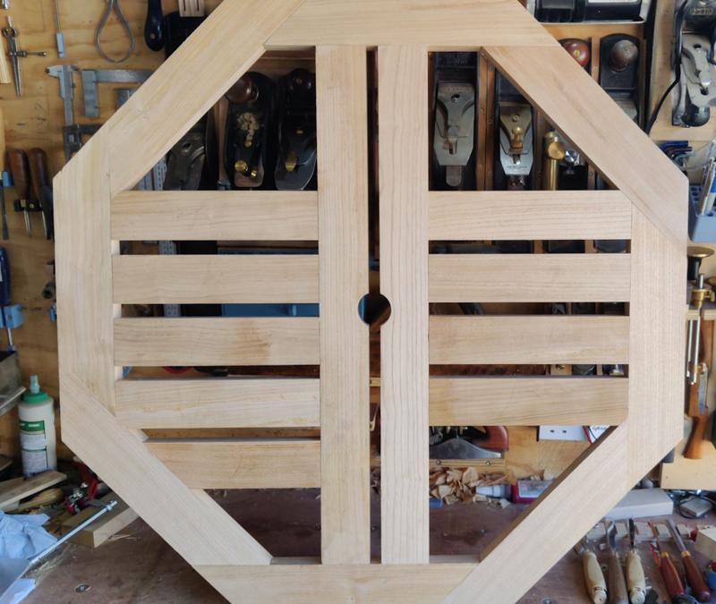
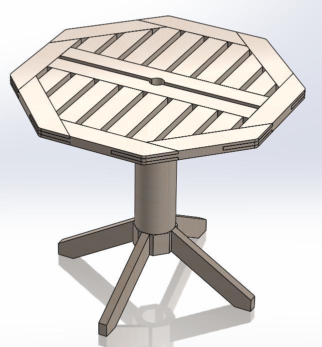
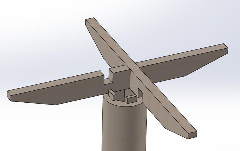
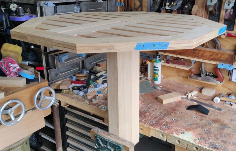
My next question would be why the need for double cross-support-thingies at the top. It's that complication which is making the joint design difficult. You're clearly seeking to align them with the slats in the table-top, but how about just rotating the top 45 degrees? That way you'd be giving support to those weaker parts of the table top, and helping hold the dovetails in their housing.....and of course, you'd only need a single cross piece in each direction, which could just drop into a housing at the top of the octagonal column.
I'd glue up the octagon in 2 halves, and then do your final adjustment planing when mating those two together.
There's absolutely no need for any splines, dowels, dominoes, or anything else, for those joins.
")
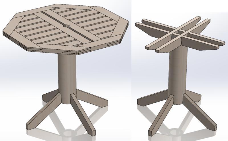
To my mind, a cylindrical turned pedestal goes with curved, rounded feet with optional carved details, but that's also something I wouldn't expect to see outdoors. For a garden table, I'd expect the aesthetic to be more solid than slender and graceful, and the octagon works much better.Sorry for asking stupid questions, but what do you mean by "a more traditional manner"? I'm not averse to changing the foot design at all; the feet were designed purely as the first way I thought of doing them.
Something like this.
To my mind, a cylindrical turned pedestal goes with curved, rounded feet with optional carved details, but that's also something I wouldn't expect to see outdoors. For a garden table, I'd expect the aesthetic to be more solid than slender and graceful, and the octagon works much better.


I also like the octagonal column , here is a thought. Feel free to discard it.View attachment 33710
Now I really don't think I would have thought of that! I'll model it & see how it looks; thanks!You could just off-set the cross to miss the hole.
") .
.I did suggest the placing the parasol in the middle of the table was a bad idea.
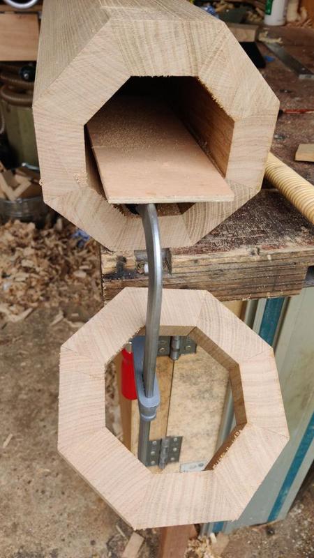
A thought has just occurred to me, probably daft. The parasol will go down through the centre of the column. Is there room between the legs for an additional stand or weight to stop the whole thing toppling over in the wind? Or will you just retreat indoors if a breeze picks up?


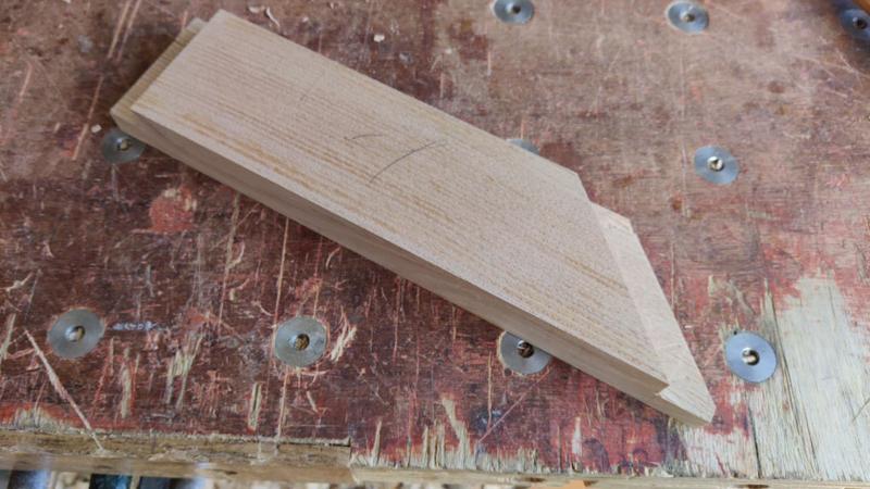
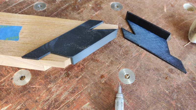
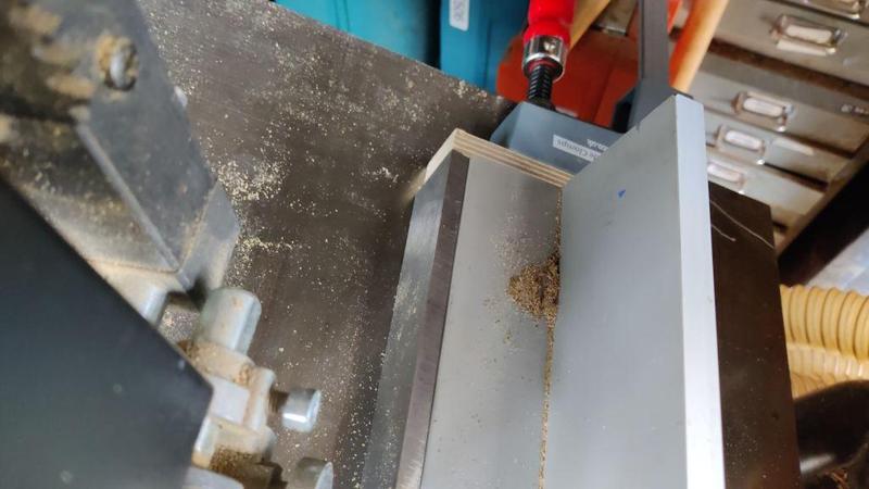
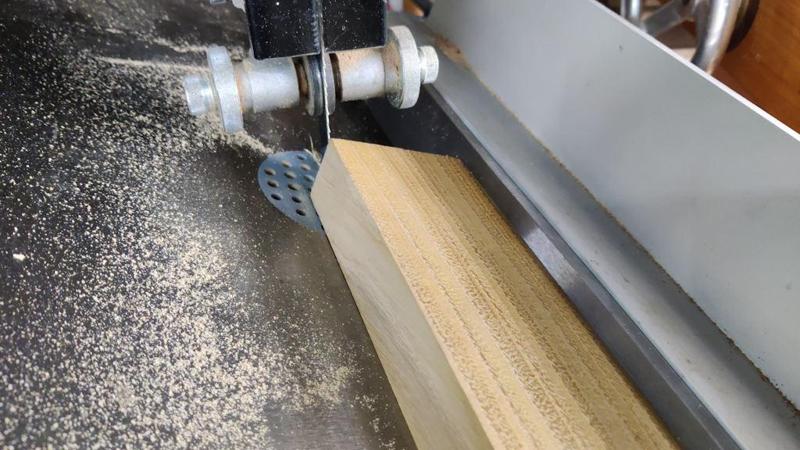
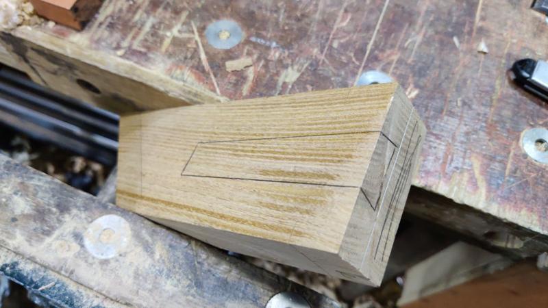
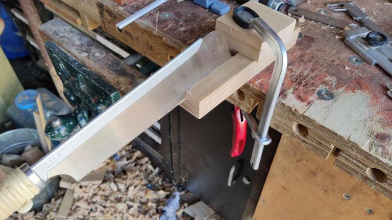
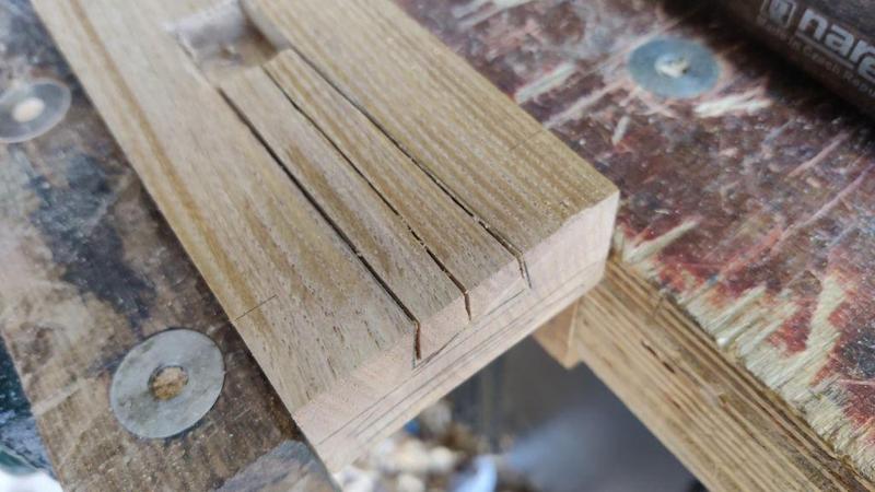
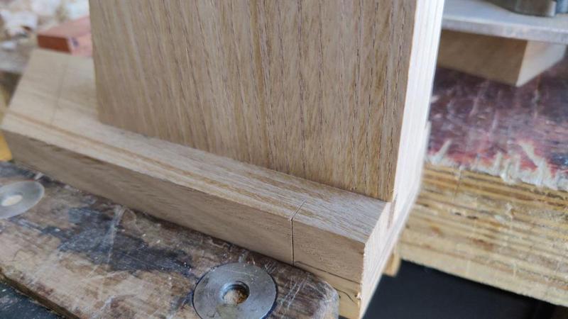
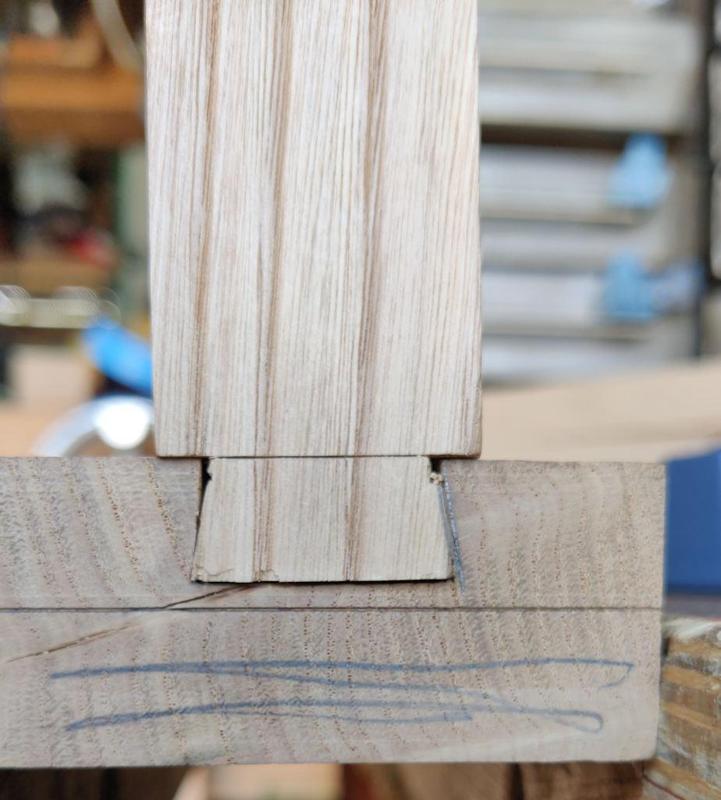
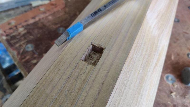
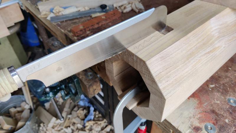
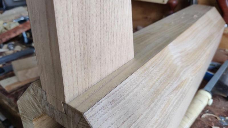
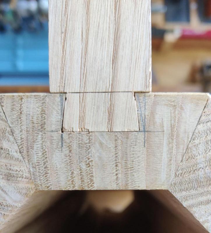
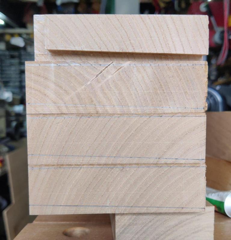
I see some sliding dovetails in your future, Al:
View attachment 33720
They'll need to be quite deep at the octagon to be strong enough.....and the complication is that the female side of the joint is with the grain.
I think you are asking a great deal of those feet-to-column joints, TBH. Looks fab, I agree, but I'm not convinced it will stand up to prolonged use, especially outside.
Sorry
S
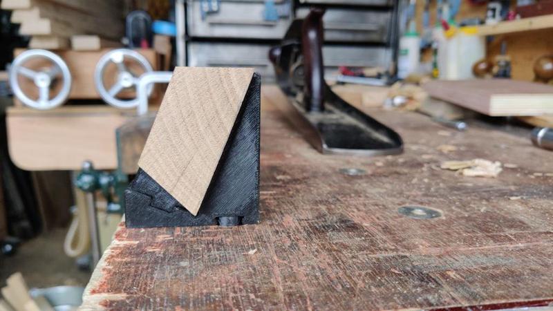
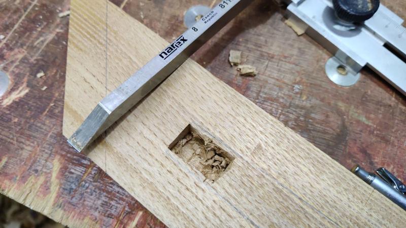
....I guess the advantage is that they're stronger than a mortice and tenon would be?.....

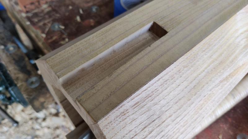
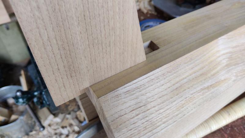
Well, you could do wedged through M&Ts....multiple per bracket/ support......but you'd have to do them before gluing the octagon together, obviously, to be able to get the wedges in. And ordinary (un-wedged) M&Ts would be relying solely on the glue.View attachment 33721


Well personally I'd have four straight legs and rails. Strong as an ox and no complex joinery. The one I made a gazillion years ago (still in use, I understand) was made like a gate-leg table so that it could be folded away for winter storage.Don't be sorry: I'm much happier with people raising concerns when I share the CAD model rather than waiting until I later share the photos of the finished joints!
What would you suggest instead for attaching the feet?

Weld up some stainless for the base, a socket to hold the column with some nice curved legs.
Well personally I'd have four straight legs and rails. Strong as an ox and no complex joinery. The one I made a gazillion years ago (still in use, I understand) was made like a gate-leg table so that it could be folded away for winter storage.
There was still a square hole down the centre to accommodate the umbrella.
View attachment 33722
I'd do the same again, but maybe not bother about making it foldable. I don't think we ever took it down, we just covered it over for the winter.
S
Are you sure you really need that cross arrangement at the top of the column? The table top looks like it will be a pretty strong item.
Why not just fit a short horizontal block say 300mm long and the width of the 2 middle cross bars to the column and screw the top on through that. have a matching pole hole in the middle of it.
I'm thinking those arms you have will be a nuisance when sitting at the table if you cross your legs and bang your knee on them.
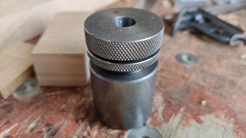
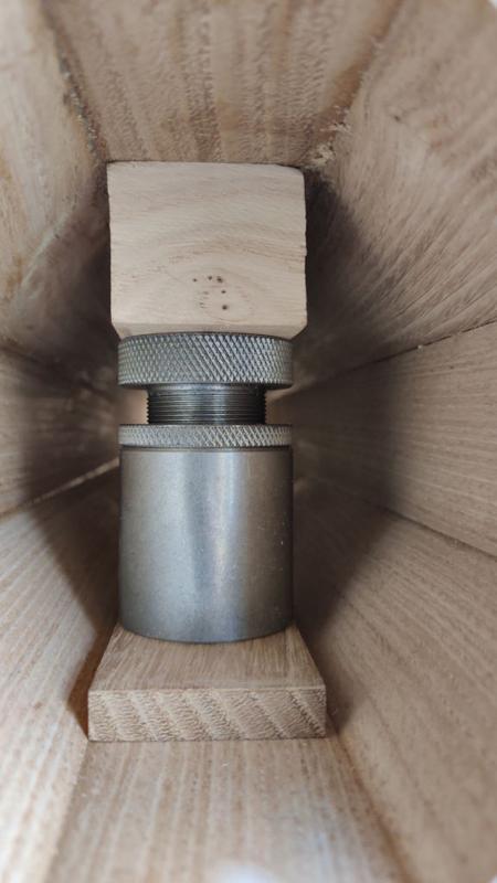
Oh and how do you secure the parasol to the cast base with its clamp screw inside the column - do you need a base? just infil the bottom of the column with a piece with a hole in it.
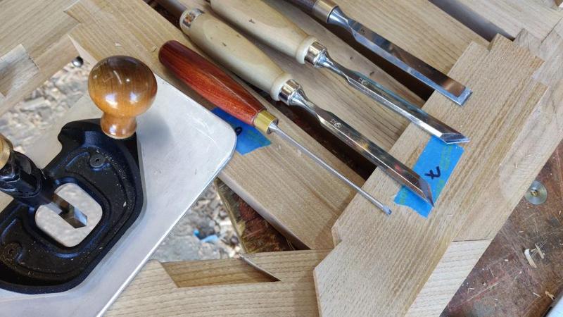
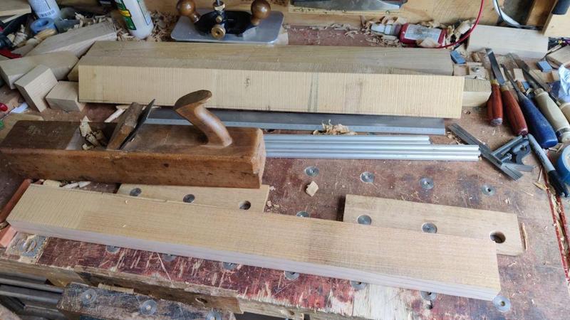
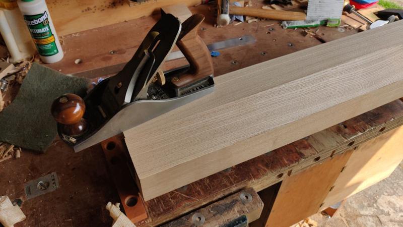
My table took ages using machines - couldn't imagine doing it with hand tools. keep going
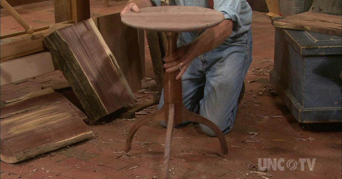
Thanks Andy, I'll give it a watch. At the moment, I'm leaning towards @Mike G's suggestion of sliding dovetails for the rails at the top, but it'll be interesting to see what he used for the legs.Al, if you do decide to go for splayed legs jointed into your very tidy column, have a look at Roy Underhill's demonstration of how to cut suitable joints using hand tools here
The Woodwright's Shop | Hancock Pedestal Table | Season 29 | Episode 10
With its turned top and dovetailed legs, this walnut tripod table is a American design.video.pbsnc.org
He uses a template (cut from tin as he seems not to have a 3D printer!) and his table is on a smaller scale than yours, but I'm sure you could beef it up suitably and make a neat job of it.
I'm still enjoying the way that youfindcreate problems, like chopping into a hollow column, thenimmediately work out a solutionscrabble around frantically trying to dig yourself back out of the hole you've put yourself in.
