NickM
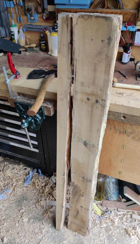
Old Oak
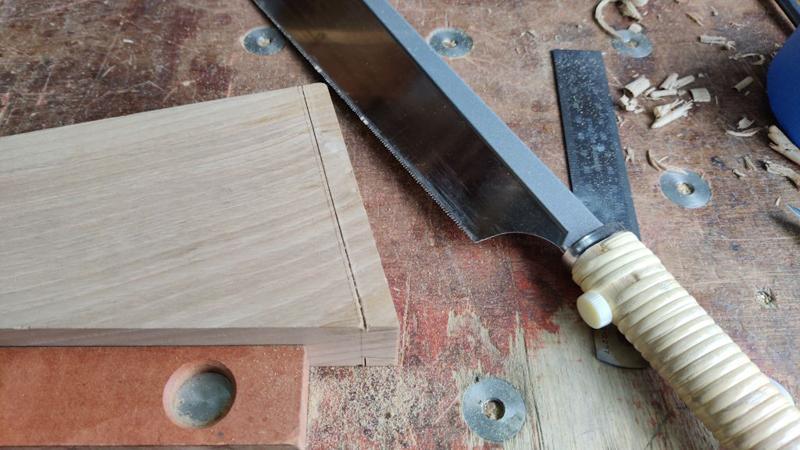
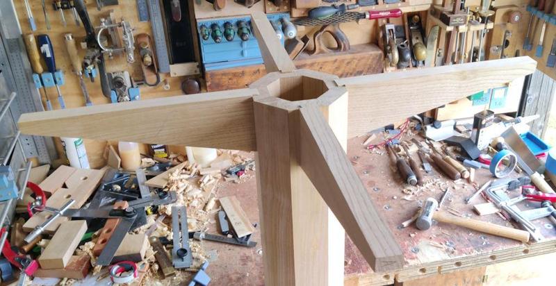
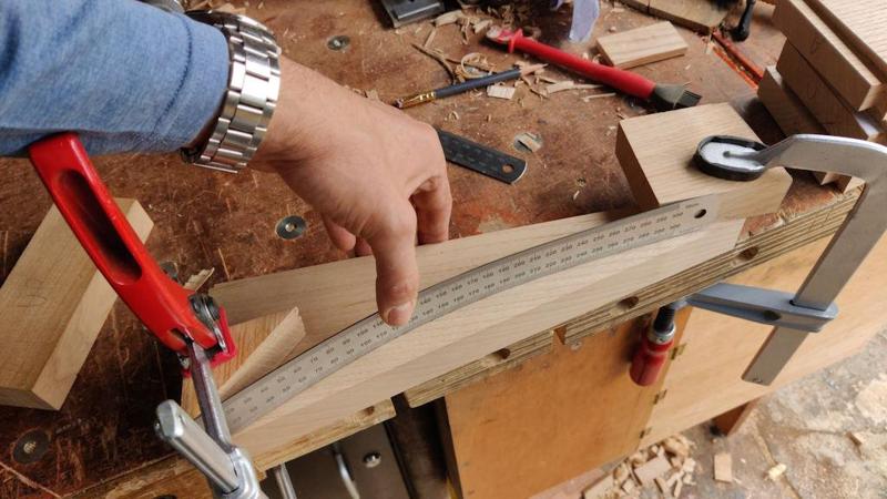
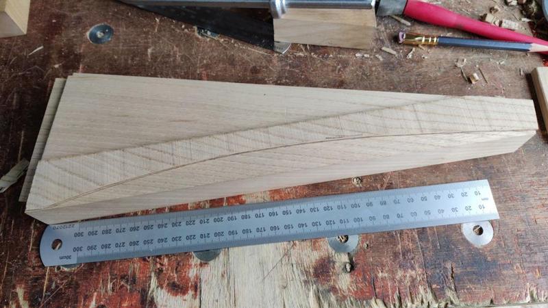
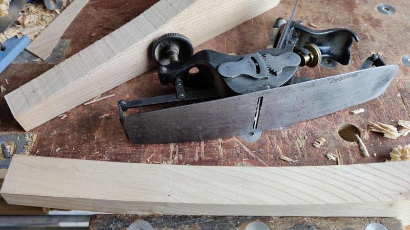
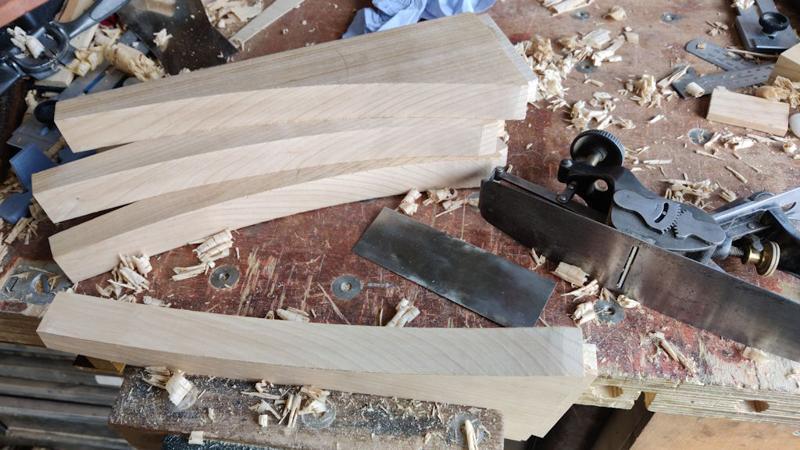
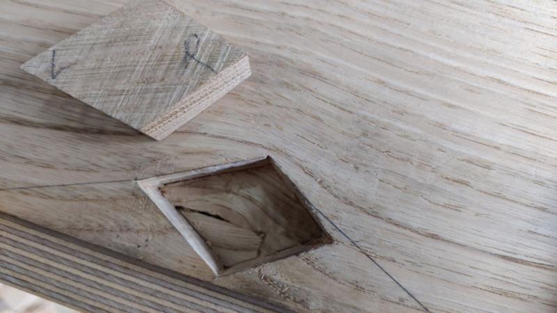
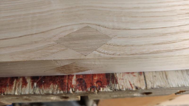
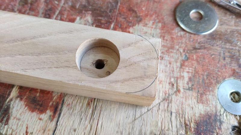
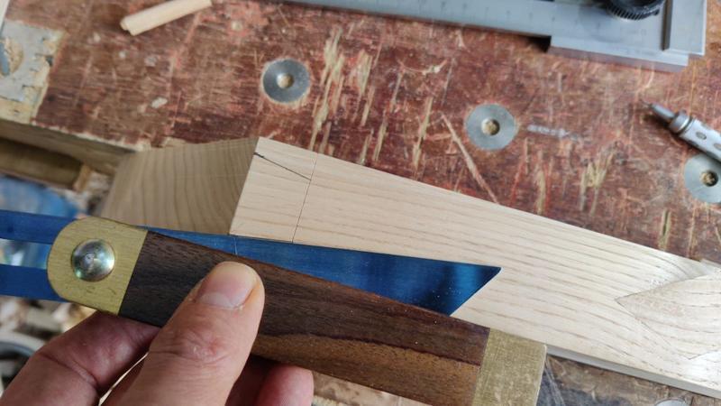
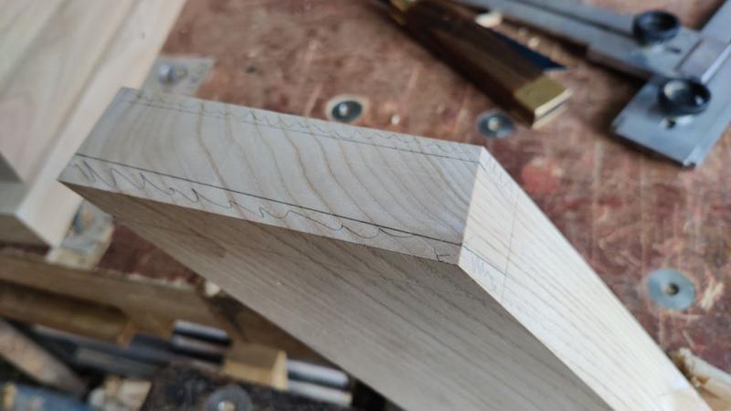
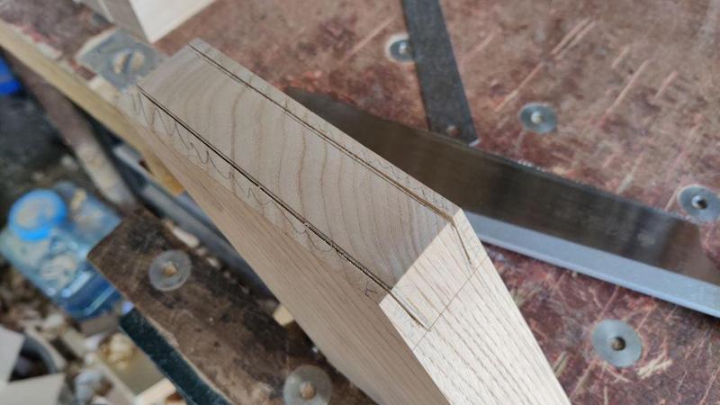
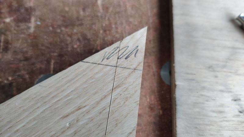
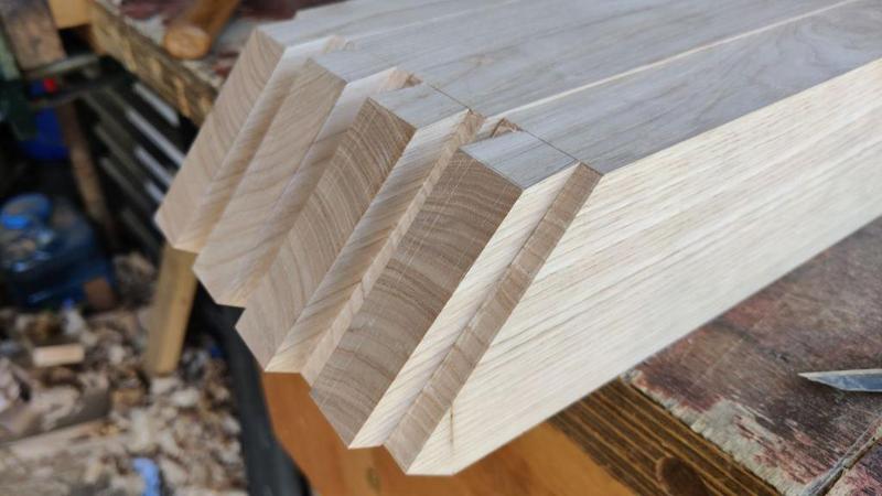
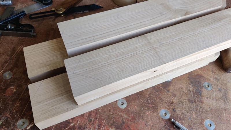
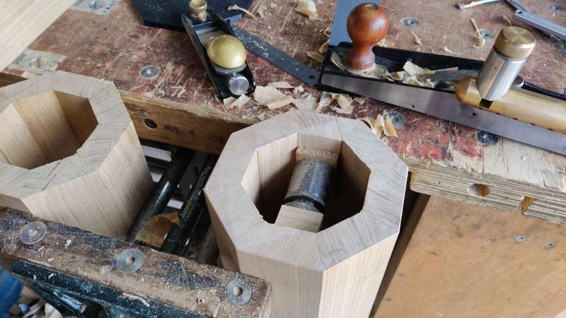
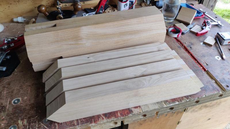
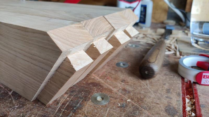
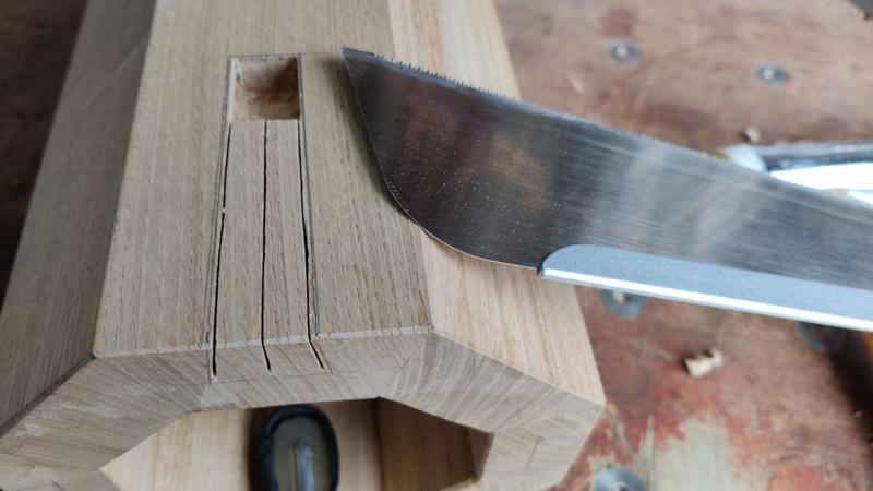
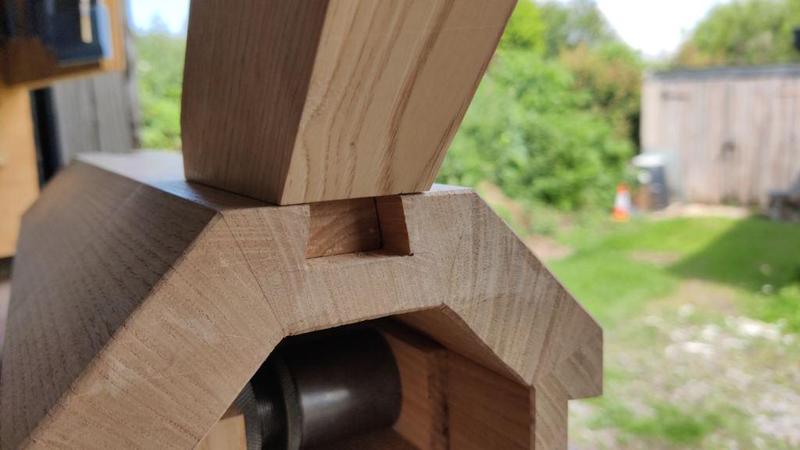
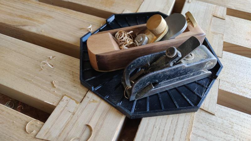
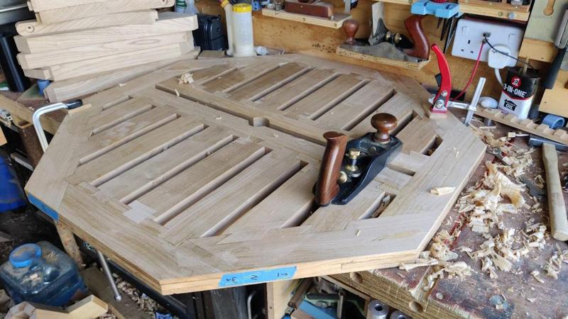
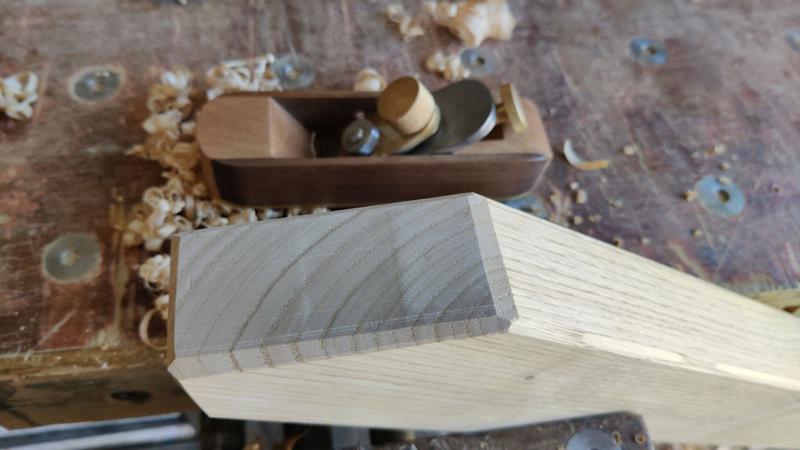
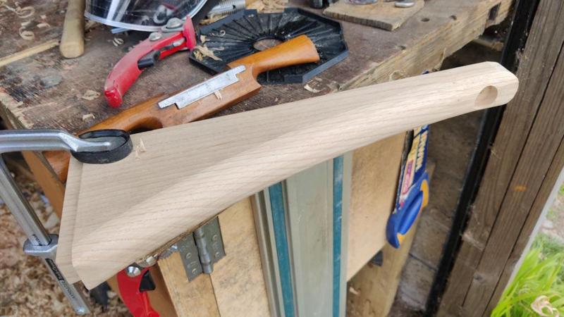
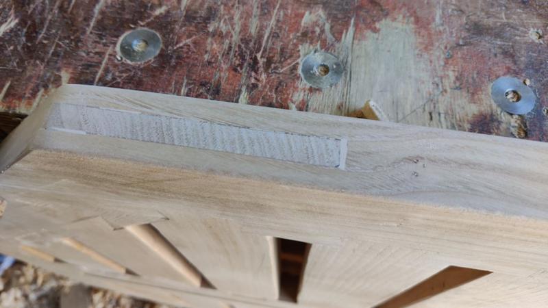
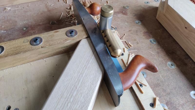
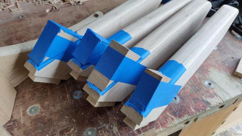
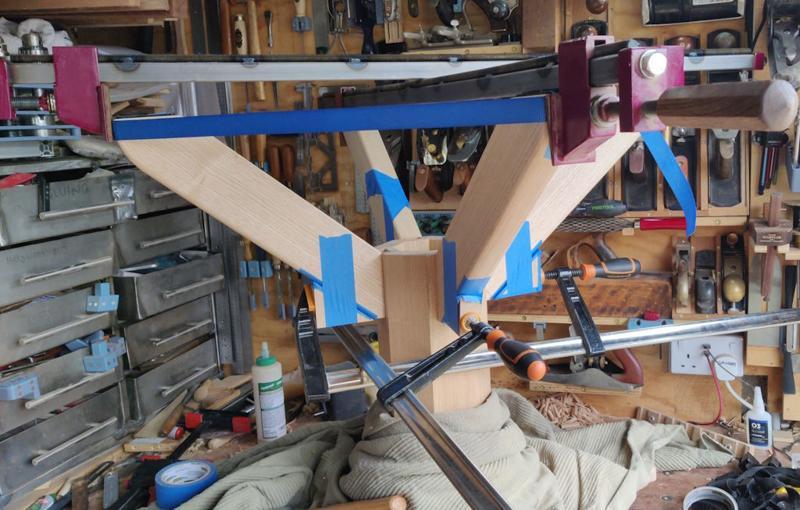
The coopered joints on the column look absolutely perfect as you can see from the bit you cut off.
I'm noting some themes here that feel very familiar... the untidy background...

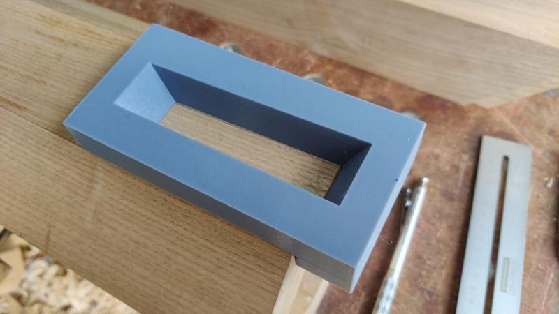
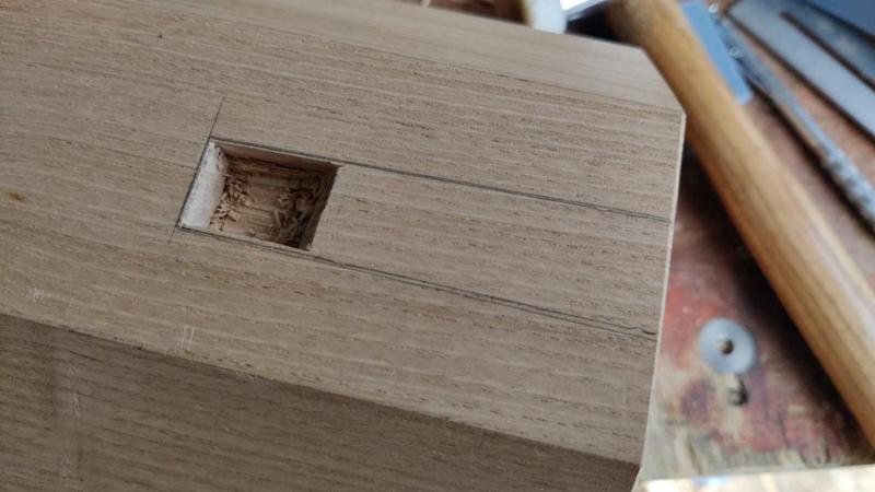
changing the design a bit so you can use a specialist tool and find out what it's good at...
Now I just need to find my own reasons why I too need a 3D printer!
")

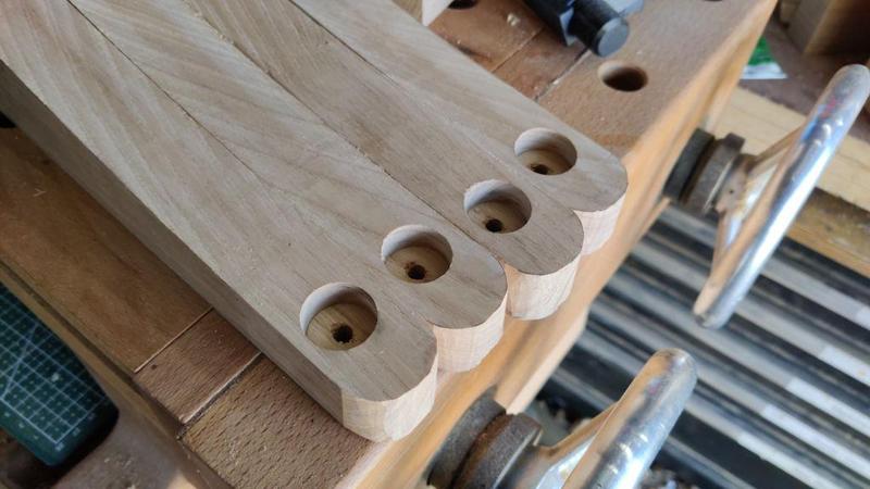
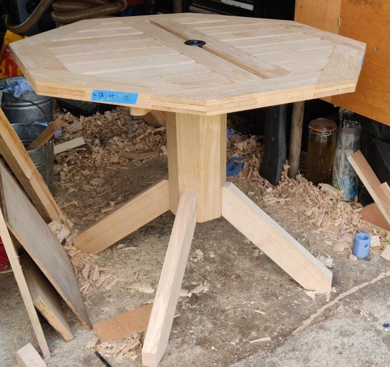
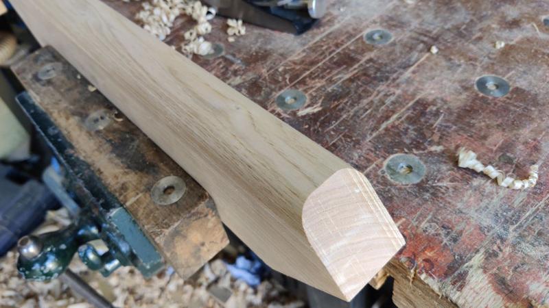
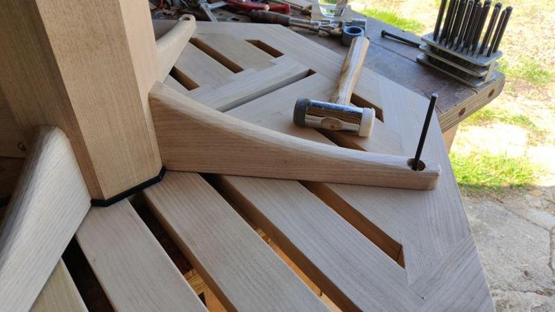
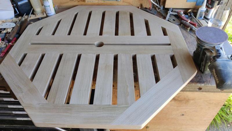
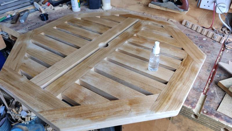
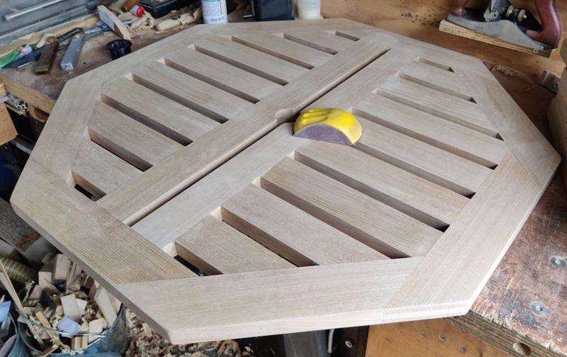
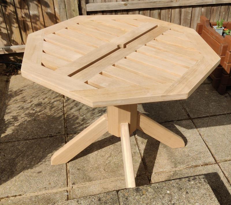
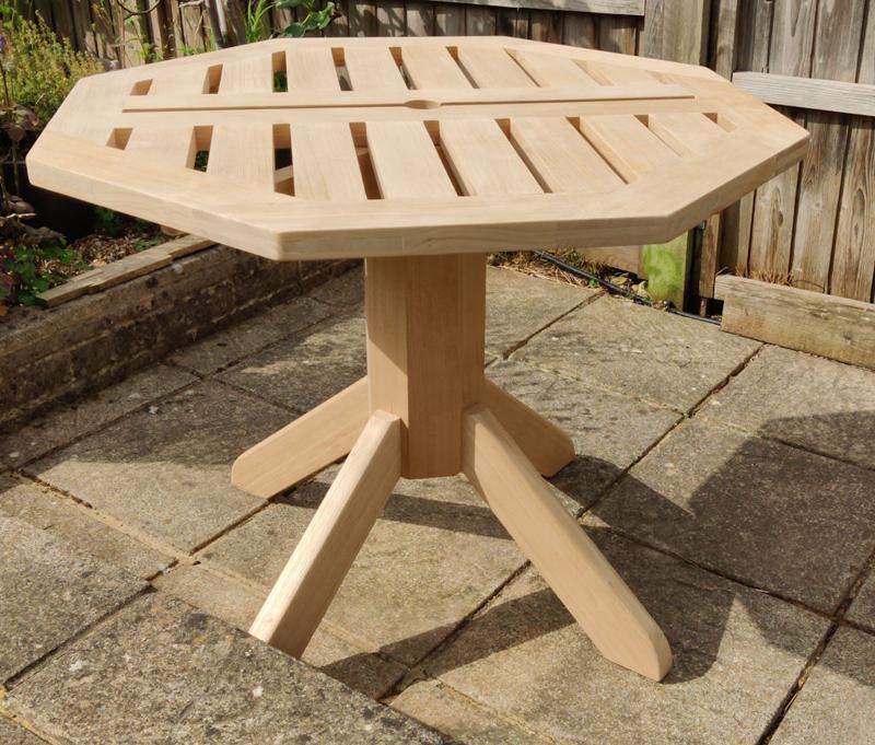
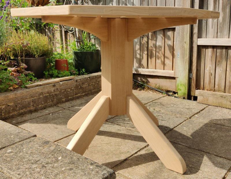
Thanks Ian. Apart from the rounding over of the top of the legs (which I've obviously already done), I'd be interested in your thoughts on what you'd do to the ends of the feet. I think they look a lot better than they did before the round-over (this photo taken before I also slightly chamfered all the edges):The only thing I can see could do with some work is the ends of the feet but as you say you want to confirm the height.
A very nice piece of work Al, you are entitled to feel proud of it.


Hmmm... let me think...I reckon you'd enjoy carving a ball and claw on each end, or maybe the sort of lion's foot pad you see on a posh cast iron bath...")
3D printing them then?Hmmm... let me think...
No.
D'ya reckon that'd look good?3D printing them then?
I think if it were me just rounding over - a bit ball like.Thanks Ian. Apart from the rounding over of the top of the legs (which I've obviously already done), I'd be interested in your thoughts on what you'd do to the ends of the feet. I think they look a lot better than they did before the round-over (this photo taken before I also slightly chamfered all the edges):
but that's not to say I think they're perfect by any means and I'm very open to suggestions for further improvements.
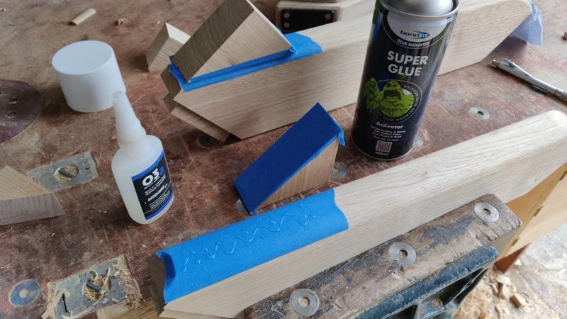
I'm contemplating adding a thin (probably 3 mm thick) plastic piece to the underside of the feet (to help stop water soaking up from the ground), but that won't really change the look of them much I think.

Thanks AndyLooks excellent Al.
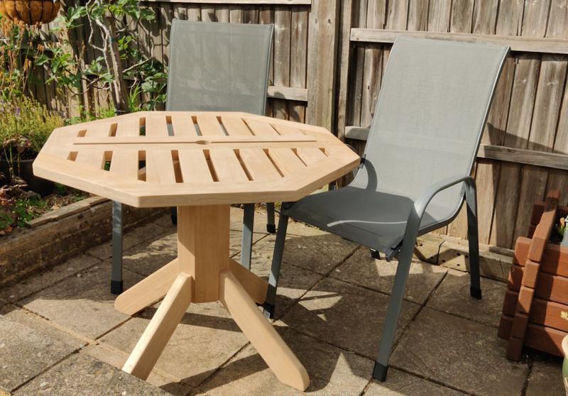
How long? Educated guess? Somewhere between 25 years & eternity.How long will it be before you start work on a couple of chairs to match.
If your pidgeons are like those up here, seconds!How long do you think I'll have to wait before a bird poos on it?!
")
It has lasted one night at least! I doubt it'll make it through the day though...If your pigeons are like those up here, seconds!
S.
Very well done Dr.Al, sturdy and pleasing on the eyes.
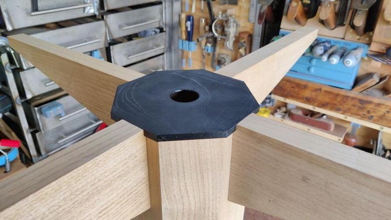
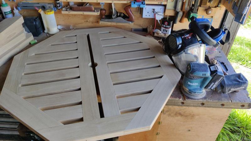
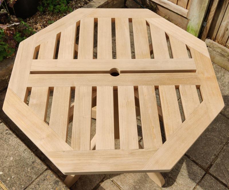
Looks really good particularly like the octagonal column, very pleasing colour too. Bet her indoors is pleased too.
Thanks Mike.Fantastic Al, well done. That's a great result, a nice project, and as always, a really good write-up.
I'm glad you rounded over the end of the feet, which softened up the look quite a lot. It's too late now, but a gentle curve out of the underside of the leg might have helped too. I'm thinking maybe 15mm deep at the mid-point, so nothing too bold.
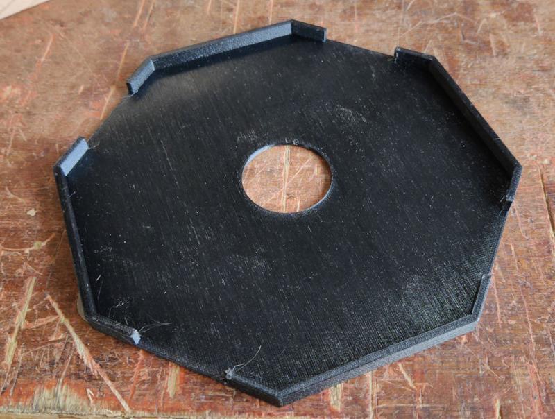
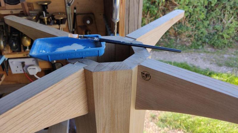
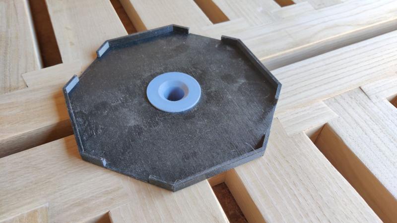
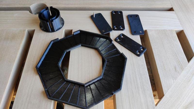
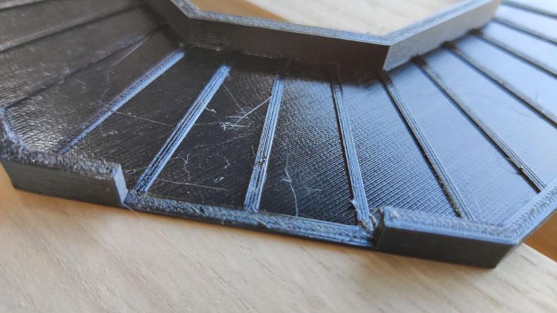
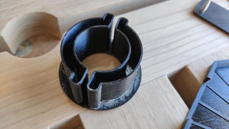
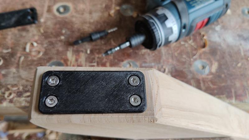
The ability to make plastic pieces adds an extra dimension, too. I've always been a bit sniffy about plastic in my projects, but it's interesting how often I'm getting DaveL to make little bits for me on one of his 3 printers.
I recognise that feeling only too well!....and just wanting to get the damn thing finished!
Indeed which is why Al’s comment about making multiples ( chairs) resonates so well with me and why I am in awe of the chair builders around here.I recognise that feeling only too well!
S
It looks great, well done. I've also been looking at the plastic pieces you printed and how you've integrated it as an invaluable tool. I guess there is a shift in mindset needed, beyond making replacements when things break, to actually use it over other materials and tools.
That's interesting about being able to be creative in limited time. I'm a designer but don't use CAD much so my skills are limited but I think I could pick it up relatively easily.
I think it will be my next tool purchase for the workshop. Interesting that you leave it running overnight, is that in the workshop or house? It needs no supervision then, not like leaving a CNC running!?


