• Hi all and welcome to TheWoodHaven2 brought into the 21st Century, kicking and screaming! We all have Alasdair to thank for the vast bulk of the heavy lifting to get us here, no more so than me because he's taken away a huge burden of responsibility from my shoulders and brought us to this new shiny home, with all your previous content (hopefully) still intact! Please peruse and feed back. There is still plenty to do, like changing the colour scheme, adding the banner graphic, tweaking the odd setting here and there so I have added a new thread in the 'Technical Issues, Bugs and Feature Requests' forum for you to add any issues you find, any missing settings or just anything you'd like to see added/removed from the feature set that Xenforo offers. We will get to everything over the coming weeks so please be patient, but add anything at all to the thread I mention above and we promise to get to them over the next few days/weeks/months. In the meantime, please enjoy!

Holiday Toolchest

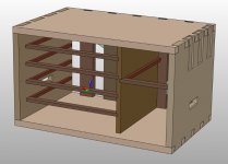
Following the conversations on the other thread, I've been thinking about drawer contents. The original plan was to make a two-part tool chest. The bottom part would have 10 drawers for small stuff and the top half would essentially be one big tote thing for planes and such-like.

I've since tried to make my life simpler by reducing the number of big tools (e.g. no planes bigger than a smoother) and to try to get everything into the one chest. There will be some things that don't go into the chest (more on that later), but they'll be restricted to stuff that can get battered around in a tool bag without me worrying about damage.

To start thinking about things, I measured (in the CAD model, which I've tried to keep up to date with actual dimensions) the inside dimensions of the drawers (left side 265×304 mm; right side 265×149 mm) and inside heights of the left-hand drawers (the right hand ones were still very much in flux).

I drew the inside dimensions out on a bit of plywood to give me something to play with:
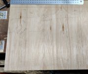
drawer_sizes.jpg

I could then lay out the drawers. I started with the left-hand side as that was a bit better defined. Five drawers, starting from the top.

The first (top) drawer would house some saws. I probably don't need three saws, but I'd be keen to take the Kataba and at least one of the Dozukis. I'm not sure what I'd use the space for if I didn't take the second Dozuki, so for now I've just allocated it some space. The saws are 20 mm thick, so they should fit easily into a shallow drawer:
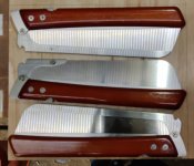
drawer_l1_saws.jpg

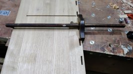
The next drawer was for measuring and marking tools. I'm not sure whether I'd bother with a sliding bevel (I rarely use it), but I've included it for now. I picked the marking gauge with interchangeable heads as it is most flexible (it has a pin head, a pencil-mounting head, a fixed wheel head and a bearing-mounted wheel head, although I've no idea what the last one of those would be good for, cutting paper maybe?).

Although the drawer is 304 mm wide, a 300 mm rule wouldn't quite fit in this drawer due to the bit at the end where the hanging hole is. I don't see that as the end of the world: although I've got enough 300 mm rules that it wouldn't be the end of the world to cut one down, rules are thin, so I can just mount it on the shooting board at the front of the chest.
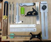
drawer_l2_marking_measuring.jpg

There's a little bit of space left in that drawer if I need to squeeze anything extra in.

The main issue is that the marking gauge I've picked is 60 mm diameter, which is taller than the highest drawer in the current plan. Given it's just this one thing that is a problem, I think the easiest solution is just to make a low-profile body for it (probably out of 30 mm brass bar with a flat on one side to stop it rolling around). Ignoring the marking gauge, the highest thing in this drawer is 28 mm.

Drawer 3 would hold a selection of chisels (exact choices to be determined, but definitely a few sizes biased towards the small ones and at least one skewed-end chisel). Chisel handle diameter is maximum 37 mm (rounded up!).
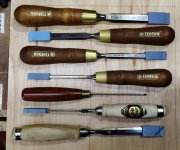
drawer_l3_chisels.jpg

Drawer 4 gets sharpening gubbins and card scrapers (highest piece is the atomiser bottle at 39 mm, followed by the honing guide at 35 mm):
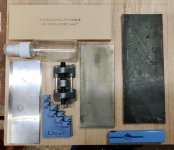
drawer_l4_sharpening.jpg

and drawer 5 (the bottom drawer) gets a bit of a miscellany of left-overs. Neither my fret-saw nor my coping saw would fit in any of the drawers (well, the coping saw might if I stuck it diagonally, but it would take up most of a drawer all on its own), so my plan is to make a smaller one - hence the reserved space. I've already got a reasonable idea of what it would look like, so it was straightforward to allocate some space for it.
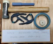
drawer_l5_mallet_fretsaw_etc.jpg

Then onto the right-hand side. With the plan to try to cram everything into the chest, I need to have space for planes in here. These are obviously way too tall for the shallow drawers of the left-hand side, but I think I can get away with an arrangement like this:
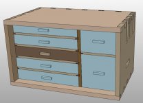
with_right_hand_drawers.jpg

I'm not absolutely convinced the bottom-right drawer is viable (partly as the length is a bit touch-and-go and partly as getting planes in and out of that drawer might be awkward), so it might instead look like this:
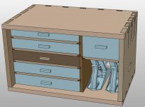
with_planes_mounted_on_base.jpg

Anyway, the bottom-right drawer has just enough space for a couple of smoothing planes, maybe..
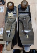
drawer_r2_shooting_planes.jpg

There are two reasons I say maybe. Firstly, that #4½ is only has about a millimetre of clearance, so it might not fit once the real drawer is made if the drawer depth is slightly off. Secondly, I've done a bit of a squander and ordered a Veritas BU smoothing plane. I'm pondering on taking a Stanley #4 and the Veritas one, but until it arrives (sometime this week probably) I won't know for certain the envelope of that plane. I suspect it will be getting very close to (or possibly going over) the 265 mm length limit of the inside of the drawer. If I get rid of the drawer and just have the planes loose in the bottom (as shown in the second CAD image above) then that'll gain a bit of extra length and also mean I can just pick them up by their handle rather than digging into a deep drawer and probably lifting them up by the blade (at least for the #4).

The remaining space in the top-right of the chest is enough for this lot (with some strategic rotating through 90° of the router-plane's blade clamp!)
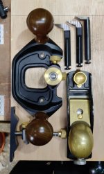
drawer_r1_planes.jpg

Having the fence for the router plane included in the kit means I can use it as a grooving plane (with, e.g., a 3 mm cutter) when making box bases.

The things that I haven't fitted into the box are (excluding all the things I haven't thought of :lol: )

  • Glue
  • Clamps: for clamping stuff down to the chest, for clamping stuff while gluing and for holding the chest down to a table or whatever
  • Cloths / paper towels
  • Finish of some sort
  • Screwdriver(s)
  • Any sort of drilling apparatus

Glue, clamps, cloths and such-like can just go in a canvas tool bag (the one you can see on the ground in the image at this link). Finish could also go in there, but it's more likely I'd just sort that out when I get home.

I've got a screwdriver bit handle, so that and some bits will probably squeeze in somewhere (e.g. with the mallet & fret saw). I'm not sure how likely it is that I'd use a drill, but I've got another plan for that anyway, so more on that later.
 
One thought - each drawer wastes some height with the space taken up by the thickness of the bottom and clearance gaps. So instead of two shallow drawers, could you do better with one deeper drawer? It could take your marking gauge as it is, the three saws stood on edge and the rules on edge. They could be further controlled by adding some thin wooden dividers, or even more economically by suitably sized/adapted open topped cardboard boxes. I think you'd have space for more tools too.
 
AndyT":1a33kz2c said:
One thought - each drawer wastes some height with the space taken up by the thickness of the bottom and clearance gaps. So instead of two shallow drawers, could you do better with one deeper drawer? It could take your marking gauge as it is, the three saws stood on edge and the rules on edge. They could be further controlled by adding some thin wooden dividers, or even more economically by suitably sized/adapted open topped cardboard boxes. I think you'd have space for more tools too.

Interesting thought; I'll have a play
 
It looks plausible. The combined inside height of the two top drawers (where the marking gauges and saws are currently allocated) is 74 mm, but add the 9 mm from losing a drawer bottom (that's what I'd allocated assuming a grooved base) and the 10 mm from the drawer divider and we're up to 93 mm. The saws are 90 mm high stood on edge. There might be a little more to gain by tweaking the sizes of the other drawers and/or setting the bottoms into rebates instead of grooves as discussed on the other thread.

saws_standing_up.jpg

(the block of wood at the back isn't intended to be in the drawer; it's just to stop the saws from falling over)
 
While all the drawer pondering carries on, I thought I'd do a bit of work on tenon wedging.

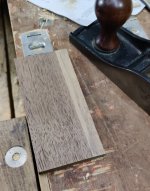
I started by digging in one of my offcut piles and pulling out this bit of American Black Walnut. I planed it down to be a very tight fit in the mortices. I'll probably skim a little off the sides with a block plane as I fit them, but I didn't want it to be a loose fit as the mortices probably won't all be exactly the same size.

01_walnut_offcut.jpg

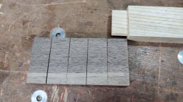
I then chopped it into lengths, each a little longer than the tenon:

02_walnut_sliced.jpg

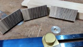
I used a sliding bevel and a square to mark them up at three different completely arbitrary and unmeasured angles:

03_walnut_marked.jpg

and them sawed them up with the Dozuki:

04_chopping_wedges.jpg

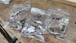
I then picked one at random from each batch and measured it and bagged them up assuming the angles of all were the same. I don't know which one I'll use yet, but I thought it best to have a few to hand (there are spares of each size as well):

05_measured_wedges.jpg

I then marked all the tenons about 5 mm from the each side:

06_marked_tenons.jpg

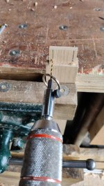
After marking the bottom of that line with an awl, I drilled a 2.5 mm hole through:

07_drilling_tenons.jpg

and then used the Kataba (as it has a thicker kerf than the Dozuki so it'll be easier to get the wedges started) to cut the slot:

08_sawing_tenons.jpg

I then got the base board out and marked a line outside of the mortices. I used one of my home-made plough plane blades as a 3 mm reference (it was made from 3 mm gauge plate). As discussed above, it seems the distance isn't too critical, but I thought that 3 mm reference would at least make them look relatively consistent.

09_marking_mortices.jpg

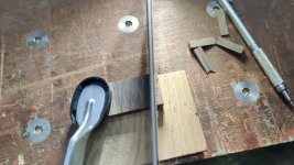
I then set up an angle gauge (set to 10° to match the 3 mm offset) to use as something to sight along when paring down the ends of the mortices:

10_chopping_guide.jpg

I've only cut the angled ends in the base board mortices so far. They won't be visible when it's assembled, so they're relatively low risk. I'm now pondering whether it's practical / sensible to fit the tenons into the base board mortices as a trial run, even though it'll be a while before I assemble the rest of the case. Probably more sensible to wait and do everything at the same time, but if I've messed up this part of the process, I'm guaranteed to mess up the top if I don't change anything!
 
Well, your deeper drawer does look like a possibility.

One word of warning though - you say this is all for a minimal, portable tool kit, but you also confess to picking up nice tools in junkshops and even ordering extra planes (new ones!) - and once you have made a place to put tools, they are likely to multiply until they fill it...

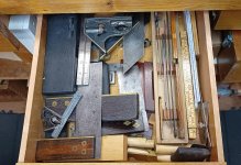
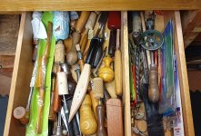
These are two of the drawers under my workbench. One is mostly squares and rules, the other is mostly knives, awls and little handy things.

IMG_20230312_134356048.jpg

IMG_20230312_134425862.jpg


On the bright side, they don't move about much ;)
 
I get your point, but remember this tool box will only be filled when I travel. There plenty of other (more accessible) places that tools will live most of the time, so any new acquisitions (which I've no doubt there will be :oops: ) can find space in the garage & don't necessarily have to come on holiday with me.
I can always remake the chest from scratch if necessary anyway - it'll keep me amused for a while doing so!
 
Dr.Al":2m6xx2d8 said:
and drawer 5 (the bottom drawer) gets a bit of a miscellany of left-overs. Neither my fret-saw nor my coping saw would fit in any of the drawers (well, the coping saw might if I stuck it diagonally, but it would take up most of a drawer all on its own), so my plan is to make a smaller one - hence the reserved space. I've already got a reasonable idea of what it would look like, so it was straightforward to allocate some space for it.

View attachment 5

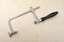
Have you considered one of these as a fret/coping saw?

jewellers saw.jpg

I've a couple of these, and they work rather well for light stuff, within the limitations of the depth of the frame. The design also lets them slide down to a smaller size when the blade is removed.
But on your past record, no doubt you will prefer to make your own.
 
Tiresias":39ulzj8i said:
Dr.Al":39ulzj8i said:
and drawer 5 (the bottom drawer) gets a bit of a miscellany of left-overs. Neither my fret-saw nor my coping saw would fit in any of the drawers (well, the coping saw might if I stuck it diagonally, but it would take up most of a drawer all on its own), so my plan is to make a smaller one - hence the reserved space. I've already got a reasonable idea of what it would look like, so it was straightforward to allocate some space for it.
View attachment 5

Have you considered one of these as a fret/coping saw?


I've a couple of these, and they work rather well for light stuff, within the limitations of the depth of the frame. The design also lets them slide down to a smaller size when the blade is removed.

But on your past record, no doubt you will prefer to make your own.

Thanks, yes: I'd seen that sort and that's basically what I was planning to make (with what I hope will be a couple of minor improvements). Part of the reason I was going to make my own rather than buying one of those is that I thought it would be an interesting challenge.
 
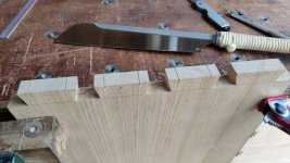
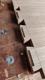
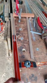
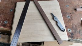
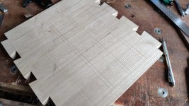
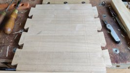
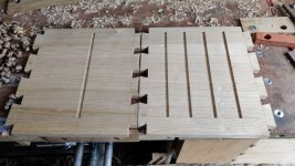
Minor update tonight. I worked out which of the big panels was narrowest (front-to-back on the toolchest) and set the panel gauge up to that size (if you remember, I hadn't bothered to do this before cutting the dovetails). I then used the panel gauge to mark the fronts of all the panels (referencing off the back as I have throughout the build):

marking_front_of_panels.jpg

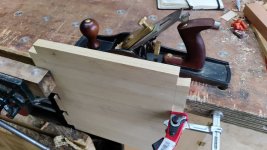
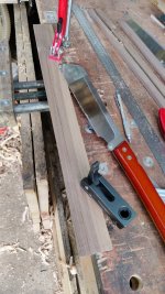
Then I planed them down to (just above) the line:

planing_front_of_panels.jpg

Not the most interesting update I'll admit, but I'm trying to get photos of everything I do on the chest.
 
I started the weekend by resawing (with the bandsaw) a lump of walnut that was 50% sap-wood. I sliced it up into circa 10 mm pieces and then planed each piece just enough to get rid of the saw marks on the dark bits of wood. I think there's enough heart wood here to cut up into strips to form the drawer runners.

01_sappy_walnut_bits.jpg

While I was at it, I also hand sawed up and planed a length of sweet chestnut to act as the anti-racking piece on the back. I didn't bother to take any photos of this as they would have looked identical to all the dimensioning sweet chestnut photos I took earlier.

At this point it started raining, which makes it much less pleasant to stand outside the workshop while sighting along the winding sticks and having the garage door shut to keep the rain out gives me much less space to comfortably plane, so I thought I'd get on with something else.

A few posts ago I made a planing stop. The design as it is at the moment calls for three of these to better support different widths of wood (and also to support the shooting board when its mounted on top). As the first planing stop looked okay to me (and I'd tried it out by clamping it in the vice of my portable workbench), I thought I'd get on and make the other two.

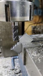
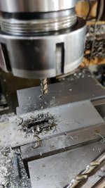
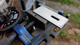
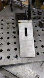
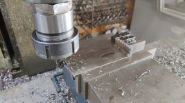
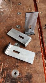
I started by using a digital angle meter thing to mount a 20 mm long bit of 5 mm thick stainless steel in the milling vice. The steel is 40 mm wide, so some simple trigonometry told me that the other two sides of the triangle formed with it an angle in the vice were each just over 28 mm long. That divides nicely by 4, so I moved the mill axes in 4 mm steps to make the teeth:

02_milling_teeth.jpg

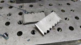
The two pieces done, each with a rough side where the end mill entered and a scruffy side where it left:

03_milled_teeth.jpg

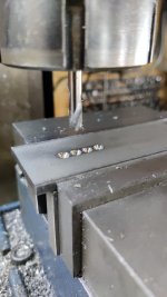
I then got a longer length of the same steel and squared up the end with the same 12 mm carbide end mill I'd used for cutting the teeth. I then swapped to a 6 mm spot drill and laid out some holes:

04_spot_drill.jpg

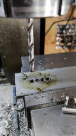
Then a 6 mm drill went all the way through:

05_drill.jpg

and a 6 mm end mill got rid of the bit in the middle and then opened the slot up to about 6.8 mm to give a bit of clearance and tidy up the sides of the slot:

06_milling_slot.jpg

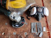
The sun had come out again by then, so I could take the parts out to the garage door and clean then up with an 80 grit flap wheel in the angle grinder. While doing this, I also added a chamfer to the squared-edge:

07_flap_disk.jpg

With that, all the parts were ready for welding:

08_all_cleaned_up.jpg
 
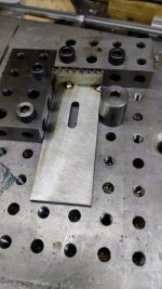
To weld the bits together, I started by holding them on a little fixture plate I made a few years ago and tacking the inside corner in a couple of places:

09_jig_for_tacking.jpg

I then flipped it over and supported it with my "welder's third hand". The chamfer is visible here: that helps get a decent level of penetration when welding:

10_held_for_welding.jpg

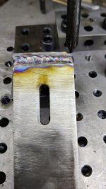
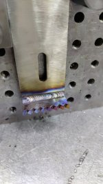
I then welded along the outside. My welding isn't going to win any awards any time soon, but I think it'll do the job:

11_welded_outside.jpg

For the sake of belt-and-braces, I also welded along the inside corner:

12_welded_inside.jpg

After a quick clean up with the angry grinder & flap disc, I put a stop on the milling machine vice and milled all three to the same length. This was completely unnecessary, but didn't take long, so what the heck:

13_mill_to_length.jpg

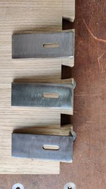
With that, I had three stops all ready to go:

14_all_done.jpg

These stops will be fitted in such a way that they can be pushed down and left flush with the top and, less importantly, the side, as you can see in this out-of-date CAD model image:

file.php


In practice, they won't be flush with the side as there'll be thumb-screws holding them in place and those will stick out. I'd originally intended to make them with countersunk slots, but stainless steel is really unpleasant to mill and the idea of milling a deep countersunk slot didn't fill me with much joy, so I went with the simple slot & will have a protruding screw.

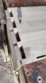
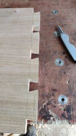
It felt like making the cut out in the end of the side panel would be a lot easier before the box is assembled. As the tails are over length, this isn't quite as trivial as you might think, so I started by marking the length that the tails were likely to end up:

15_marking_end_point.jpg

I then used the stops as a reference for marking the inside face of the side panel:

16_marking_inside_face.jpg

I could then mark out the bit that would be cut out of the end grain (note the loss of concentration where I marked the tail nearest to the front of the box, which won't get a planing stop):

17_marked_cutout.jpg

I could then put the side in the vice and saw 5 mm down:

18_sawing_cutouts.jpg

For now, I've just chiselled out a bit on the inside face:

19_chiselled_a_bit_out.jpg

I'll probably do the rest of the chiselling after the box is assembled as that'll make it easy to see exactly which bits need to be removed, but the sawing and the bit I've chiselled out will make it easier (I think) to make it all look tidy when I do that.
 
The sun was back out again this afternoon so I opened the garage door and got on with a bit more wood bothering. I started by taking those walnut pieces and slicing the heartwood bits into strips. Where they were nice and wide, I did it like this:

01_sawing_wide_pieces.jpg

Once things got more narrow (which wasn't on many pieces as there was so much sapwood), I used a different approach:

sawing_narrower_pieces.jpg

That left me with a pile of strips that were planed on three sides but inconsistent thicknesses:

rough_sawn.jpg

This felt like a good time to cut them to (approximate) length and shoot the ends square. Given they're only approximate length, shooting the ends square is probably pointless at this stage, but I like using the shooting board and it didn't take long:

cut_to_length_and_shot_square.jpg

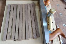
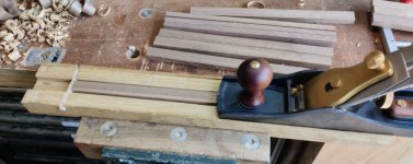
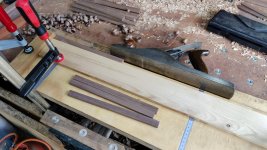
I then resurrected a jig that I made for making Kumiko. It has a slot sized for making 16 m × 3 mm strips, so I used a router plane to make that more like 22 mm × 9 mm (I didn't actually measure the dimension, I just made it wide enough for the widest strip and thinner than the thinnest strip). It was then a quick job to bring all the strips to the same thickness:

thickness_jig.jpg

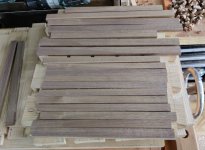
Et voila:

thicknessed.jpg

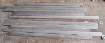
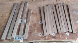
The ones on the left (which are about 22 mm wide at the moment) are intended to be the strips across the front between the drawers. The ones on the right (which are about 16 mm thick at the moment) will be the drawer runners.

I've made enough for four sets of runners (and hence 5 drawers) on the left hand side and one set of runners on the right hand side. Now I find myself at the crunch point: I need to decide how many left-hand side drawers to make: whether to put the saws in with the measuring tools and have four drawers or separate them and have five. Every time I think about it I change my mind, but I'm going to have to commit soon!

I also need to decide what to do about joinery for the front strips. I'm very tempted to have a go at the mini blind mortice suggested by AndyT. Alternatively, I could do the half-lap joint shown in this CAD model:

file.php


The big advantage of the half-lap joints is that I could size and fit the strips across the front (drawer dividers) after I've assembled the chest frame. Also, the drawer runners could be fitted into their housings before assembling the chest. That would probably make the chest glue-up much less stressful.

Doing it with blind mortices would look better (assuming I don't make a mess of what would probably end up being a circa 3 mm mortice & tenon!). However, I'd have to get the length of the drawer dividers right in advance and the glue-up would involve dovetails, the middle upright's housing joints, the wedged mortice and tenon joints, the blind mortices in the drawer dividers and the housings for the drawer dividers. I'd then be reaching into fairly narrow slot to do up the screws at the back of the drawer runners. That all sounds fairly stressful!

Making that decision is less pressing than deciding on the drawer heights (as I think the next job is to cut the housings for the drawer runners), but it's definitely something I need to decide very soon.
 
It's looking good and you are clearly enjoying solving the problems you are finding in such an original piece.

One hint, if I may. What I did on mine, to make the tiny mortises in the front side-to-side piece, was to plough a 3mm groove all the way along. The front to back runners are constrained by being fixed to the sides of the box, so it doesn't matter that there's a long gap along the groove, and the tenons only need to be tiny 3mm stubs.

In really high grade work you would groove the front to back runners as well, and then insert thin dust boards between the drawers, slid into the grooves.

But as ever, there are many right answers to choose from.

Also, I noticed that you didn't measure those little strips, but just sized them by the material.You're definitely leaving off your engineer's hat and thinking like a woodworker !
 
AndyT":36f77onz said:
It's looking good and you are clearly enjoying solving the problems you are finding in such an original piece.

One hint, if I may. What I did on mine, to make the tiny mortises in the front side-to-side piece, was to plough a 3mm groove all the way along. The front to back runners are constrained by being fixed to the sides of the box, so it doesn't matter that there's a long gap along the groove, and the tenons only need to be tiny 3mm stubs.

That's a really good idea and I don't think I would have thought of it, so thank you!

AndyT":36f77onz said:
In really high grade work you would groove the front to back runners as well, and then insert thin dust boards between the drawers, slid into the grooves.

Ah, that's quite cunning. I don't think I'll do this on the chest as it would restrict access for clamps going into the back of the chest, but it's nice to know what others would do.

AndyT":36f77onz said:
Also, I noticed that you didn't measure those little strips, but just sized them by the material. You're definitely leaving off your engineer's hat and thinking like a woodworker !

It's definitely a change in the way I naturally work! :)
 
Another thing I'm thinking about while pondering on the drawer count is all the various types of workholding this chest needs to handle. When I originally came up with the concept, it had an array of holes on the top and the back and those holes would handle most of the cases I wanted to deal with.

The cases I want to be able to handle are (all with relatively thin bits of wood):

  1. Planing a surface against a stop
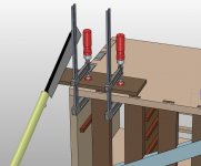
  2. Clamping a workpiece to the top so that I can (e.g.) saw a bit off the end or the side
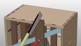
  3. Clamping a workpiece to the back so that I can saw or mark up dovetails
  4. Clamping a workpiece to the top with full access to the top surface for grooving / routing

The first one's nice and easy: that's what the planing stops are for:

planing.jpg

The second one might be okay. The anti-racking thing on the back might get in the way of clamping stuff on the right-hand side of the back, but I can either hang it off the left or spin the box round and clamp it from the front:

left_handed_sawing.jpg

Ideally, there would be a way to clamp stuff leaving the whole of one long edge clear, but for relatively narrow workpieces, that would require a very deep jawed clamp (about 300 mm from jaw pad to shaft). That's one disadvantage of losing the holes in the top, although I do like the fact that the top is actually sealed and stops stuff falling into the drawers (although there will still be a bit of a route in from the back due to the gap where the drawer runners are).

The third one should be fine:

dovetail_sawing.jpg

The last one I currently have no solution for. My dog hole tail vice would have worked (for stuff over 12 mm thick) if the holes were there in the top, but it obviously won't help without those holes.

I'd wondered about something akin to a machinist's low profile clamp, but bearing on a dovetail groove rather than a t-slot (as I suspect I have a little more chance of cutting a dovetail groove with hand tools than doing a t-slot), but the groove sounds very difficult to get right and I'm not sure it's a very good answer anyway. An easy option would be to plough a 19 mm wide groove in the top and set some t-slot extrusion into the top (which could then be used with some sort of low-profile clamp), but that seems a bit naff...

Needs more thought.
 
Hi Al, lovely clear drawings, can’t seem to understand what the significance of over 12mm is, what would a dog hole vice enable you to do particularly pls? I’m thinking that stuff against your planing stops plus a Doe's foot and cramp would work for most situations.
Ian
 
Cabinetman":epz0mdoh said:
Hi Al, lovely clear drawings, can’t seem to understand what the significance of over 12mm is, what would a dog hole vice enable you to do particularly pls? I’m thinking that stuff against your planing stops plus a Doe's foot and cramp would work for most situations.
Ian

A doe's foot might work, yes. I hadn't considered that (which is a bit daft given that I was using one on Friday!). Even if it wouldn't work I guess a few bits of thin wood clamped around the workpiece would stop it moving laterally and if the wood pieces were long enough they wouldn't restrict access to the top.

The significance of the 12 mm is that my dog hole tail vice is 12 mm thick so if I used it to clamp (say) 8 mm stock and tried to use a router plane on the top surface, the router plane would hit the tail vice.
 
Dr.Al":plzpwvqu said:
The significance of the 12 mm is that my dog hole tail vice is 12 mm thick so if I used it to clamp (say) 8 mm stock and tried to use a router plane on the top surface, the router plane would hit the tail vice.

You could get round that by slipping one or two bits of 6mm wood underneath the bit you are planing, to raise it up above the tail vice. Easy enough in the workshop if you keep a handy box of useful scraps by the bench, but not so easy when travelling.
Could some removable component do double duty perhaps? Maybe a couple of drawer dividers or something similar?
 
AndyT":3kbcvnfm said:
Dr.Al":3kbcvnfm said:
The significance of the 12 mm is that my dog hole tail vice is 12 mm thick so if I used it to clamp (say) 8 mm stock and tried to use a router plane on the top surface, the router plane would hit the tail vice.

You could get round that by slipping one or two bits of 6mm wood underneath the bit you are planing, to raise it up above the tail vice. Easy enough in the workshop if you keep a handy box of useful scraps by the bench, but not so easy when travelling.
Could some removable component do double duty perhaps? Maybe a couple of drawer dividers or something similar?

Yes, possibly, but then I'd have to go back to having holes in the top :( ;)

Andyp":3kbcvnfm said:
Just a thought, a rotating head mini vise maybe food for thought. Something like this but a bit smaller

https://garrettwade.com/product/ultimate-versatile-vise

I've got a vice of a similar sort of style to that, although I donated it to the other half to use for leatherwork jobs as I was never using it. I'm not sure how useful it would be though as I'm envisaging things like carving into wooden box tops and ploughing grooves with a router plane and the parts for those probably wouldn't fit into a vice.
 
Fair enough. I was thinking about the ability to hold a board vertical for sawing dovetails as in your 3rd image above. Emptying the box in order to pass a g-clamp through the back seems a little awkward to me
 
Andyp":14u1kg1a said:
Fair enough. I was thinking about the ability to hold a board vertical for sawing dovetails as in your 3rd image above. Emptying the box in order to pass a g-clamp through the back seems a little awkward to me

True, but there are always going to be compromises in trying to make something be a workbench and a tool chest at the same time. The top drawers will probably have to be removed to clamp stuff to the top. I might be able to just slide the drawers forward rather than completely removing them if I want to clamp stuff to the back.
 
First a bit of serendipity, then I'll come on to what I've been doing this morning.

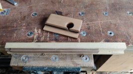
I thought I'd do a bit of playing with some of the offcuts from the walnut drawer runners. I got a bit of scrap sweet chestnut and ploughed a rebate into one corner. I then screwed a small piece of walnut into the end:

01_ploughed_groove_in_scrap.jpg

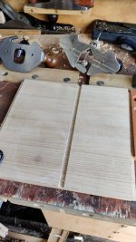
The wood strips turned out to be 9 mm thick. Making a 3 mm wide groove in the middle of the strips thus means making a groove 3 mm from the edge. A year or two ago I made a simple set of grooving planes and one pair of those were designed to make a groove 3 mm deep, 3 mm wide and 3 mm from the bottom of a box. That worked perfectly for these pieces, so will save the faff of setting up a combination plane:

02_ploughed_groove_in_test_piece.jpg

I've only used it in an offcut at the moment as I'm still pondering on the somewhat daunting assembly implications of doing this, but it's nice to know that the groove making will at least be straightforward.
 
I decided I couldn't put it off any longer and it was time to make some decisions and cut some housings. I've done one so far and it hasn't gone perfectly, but it could be worse. I've decided to go with 5 drawers on the left and one on the right with an opening at the bottom right for the smoothing planes (as shown in most of the recent CAD models). Hopefully I won't regret that later!

I started by marking the positions of the tops of the drawer runners on the middle upright piece (measured from the bottom of the chest):

03_marking_tops_of_shelves.jpg

I then put the middle shelf on the side piece and transferred the marks across.

04_transferring_marks.jpg

The top marks could be extended all the way across the middle upright:

05_extend_top_lines.jpg

and I used one of the "thicknessed" pieces of walnut as a reference to mark the bottoms of the housing joints:

06_marking_bottoms_of_shelves.jpg

A similar method was used for the two outside side pieces, but marking them as stopped housings, with the distance from the back gauged with one of the tenoned uprights and the distance from the front gauged from the back with one of the tenoned uprights and the middle support piece.

07_marking_stopped_housings.jpg

These housing joints could be open at the back, but I thought it would look slightly better to have them end at the same point that the middle support housings will end. I obviously need to think about wood movement here and leave a bit of a gap when fitting the runners.

After a little bit of chiselling to start the cuts, I then used two router planes again: the Veritas one with a 6 mm cutter to get rid of most of the waste and the Stanley one with a 5 mm cutter to remove the last little bit. This combination seems to work well. The Veritas one has the excellent depth stop which makes it easy to work gradually down to an approximate depth, but the Stanley one has a much, much, much better clamp so once you've locked a depth in, it doesn't move. At some point I'll probably machine a new clamp screw for the Veritas one as it seems far too prone to loosening in use.

08_first_housing.jpg

This first housing didn't go perfectly. After cutting down a millimetre or so, I did a test fit and found that the runner was a really good fit at the front edge of the support but very loose at the back. I don't know how this happened, but I re-marked the width of the housing (essentially a tapering knife cut at the bottom of the housing-joint-to-be) and carried on. That left a bit of a step at the back:

09_step_at_back.jpg

It's now a tight fit with the drawer runner, but with a gap underneath the back of the drawer runner:

10_with_test_piece_fitted.jpg

That gap only goes 60 mm or thereabouts along the rear end of the housing joint (which will be hidden by one of the back upright pieces), so I'll probably just live with it. I'll double check all the other housing widths before cutting them ("measure twice" and all that :D ). I'm pleased I started with that one as it's the only one where the back of the joint will be completely invisible :)

Somewhere in the process, something obviously got caught under the router plane and ploughed an extra little groove in the surface of the upright:

11_scored_top.jpg

It's not especially deep, so I'll first try a damp towel and an iron and see what that does. Failing that I can just thin the side down slightly with a smoothing plane.

Hopefully the other housings will go more smoothly...
 
The iron & damp tea towel trick worked very well. You can still see the score mark if you look closely, but I think it'll take very little effort with a smoothing plane to make it look immaculate.

Before:

file.php


After:

post_ironing.jpg
 
The housings on the other side of the middle support went the same way. I checked the line positions before starting to cut and they looked to be slightly on the tight side so I thought that was a safer bet than the alternative and got on with the chiselling and router planing:

upright_second_set_of_housings.jpg

They were indeed a bit too tight to fit the runners in, but that gave me an excuse to get this side rebate plane out, which I've played with in the past but never used in anger. I only took material away from the side of the joint that would be against the bottom of the runner as I'd used the side that forms the top as the reference when transferring marks between pieces.

side_rebate.jpg

The fence was handy for making sure I didn't tunnel into the corner, although I didn't bother with it when doing the far end of the joint (which I did in the reverse direction using the other blade to avoid breaking out the end):

side_rebate_fence.jpg

This is fairly typical of the fit. It's a very snug fit that needs a little bit of persuasion with a mallet, but really not much at all: a couple of light taps and it goes in:

fit.jpg
 
Another small bit of progress this weekend in between sociable stuff.

First of all, I double checked the thicknesses of the knife marks for the remaining housing joints: I wanted to get them right first time this time rather than needing to clean them up with the side rebate plane.

01_double_checking_marks.jpg

Everything looked right, so I got on with the housings using the same method as before: knife and chisel to get started, then two router planes (one with the depth stop just above bottom depth and one fixed at bottom depth) to remove the rest of the waste. The new screw for the Veritas plane worked really well: it didn't come loose once during the whole process (previously it was coming loose about a third of the time, so that's a big improvement).

All the housings are now cut ready for their walnut drawer runner inserts.

02_all_housings_cut.jpg

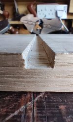
I'd already thicknessed (by hand but with a jig) all the walnut pieces, but they were still rough cut on one edge. I could have carefully planed them down to the scribed line, but it seemed easier to use my along-the-bench shooting board. Generally I don't get on with this shooting board: I prefer my fancy one, but to be honest I prefer every other type I've tried so far as well. However, one thing this board is really good for is clamping a bit of scrap wood to it and using that as a back stop and planing lots of pieces down to the same width:

03_widthing_walnut.jpg

With that, I have a pile of bits of American black walnut in two different widths: 16 mm for the (front-to-back) drawer runners and 20 mm for the ones that go across the front between the drawers.

04_withed_walnut.jpg

I think the next job is probably to cut the grooves in the back of the 20 mm front pieces (as per AndyT's suggestion) and the matching tenons in the 16 mm front-to-back pieces. I think I'll then be able to fix the front-to-back pieces in place (with a screw in a slot at the back and a bit of glue at the front) ahead of assembling the rest of the chest frame.

I also need to cut the hand-hold slots in the two side pieces.

latest_model.jpg

It's starting to feel like I'm probably getting close to the scary bit where I glue all these bits together :eusa-shifty:
 
I bet you're learning an awful lot at the moment, Al, by doing this project. I certainly didn't attempt anything as complicated as this until I'd been woodworking for quite a few years.
 
Mike G":2bhxjg1o said:
I bet you're learning an awful lot at the moment, Al, by doing this project. I certainly didn't attempt anything as complicated as this until I'd been woodworking for quite a few years.

I certainly am, yes!

It was part of the appeal of the project. At the end of the day, if it looks a bit shabby it won't matter too much (it's a tool chest, not a piece of furniture on display in the lounge), but it's great to have an opportunity to really stretch my skills and experience and try things I haven't tried before. I've no doubt there will be mistakes and things that aren't quite right that'll bug me a bit when I've finished, but I can always make another one with what I've learnt! It's more about the process than the end product for me and I'm enjoying the challenges associated with doing new types of joints and figuring all this stuff out.
 
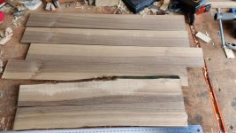
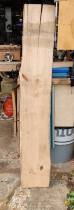
In the spirit of putting off the big scary glue-up for as long as I can, I thought I'd use my first free day since feeling properly better after covid to do some more stock preparation. I need quite a lot of thin-ish, preferably quarter-sawn, pieces of sweet chestnut to make the sides and backs of the drawers. This plank is destined to become those drawer pieces:

01_plank.jpg

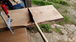
I started by chopping it into what I think are sections of the right lengths for the various drawer pieces:

02_chopping_to_length.jpg

The end bit had a big crack down the middle, so I just pulled it apart.

03_chopped_and_split.jpg

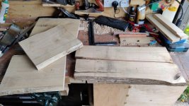
One side of the end bit had a crack at an awkward angle and my first thought was that the piece would just end up as firewood, but then it occurred to me that I might be able to get a couple of drawer sides out of it, so I put it back with the other bits:

04_cracked_piece.jpg

The shorter pieces got marked up so that the side pieces (which are somewhere near quarter-sawn) can get used and the middle bit discarded:

05_marked_up.jpg

After extensive use of my big Ryoba, I now have a big pile of bits:

06_pile_of_bits.jpg

This afternoon I'll start planing the faces of these. I think I'll plane each face until it's flat and twist-free, without worrying about the relationship between the two faces. I'll then resaw them twice on the bandsaw, with each face against the fence and hopefully that will give me two 8–10 mm thick pieces from each of the little planks.
 
You are clearly having a lot of fun with this. I can see the difference between "oh no, I've got all this work still to do" and "great, I can carry on doing more of the same, getting better and more confident at sawing and planing" .

And I still admire the idea that you'll take some woodworking away on holiday with you, when others would be dully idle on a beach.
 
AndyT":jvoevmiz said:
You are clearly having a lot of fun with this. I can see the difference between "oh no, I've got all this work still to do" and "great, I can carry on doing more of the same, getting better and more confident at sawing and planing" .

To be honest, I am starting to get the "got all this work to do" feeling, but only because I'm running out of time before I go on my next self-catering holiday. Including this one, I have 5 free weekends left and it feels like there's a heck of a lot more work to get through (I haven't even begun to think about how I'm going to hold the tools in their drawers, although I'm sure some inspiration will come from looking at Derek Cohen's photos). I'm still trying to keep the power-tool stuff to just resawing with the bandsaw, but we'll see how long my resolve lasts as the pressure builds!

AndyT":jvoevmiz said:
And I still admire the idea that you'll take some woodworking away on holiday with you, when others would be dully idle on a beach.

I'd go spare sitting idle on a beach for more than an hour or two a year! Definitely not my thing. Before Carolyn got M.E., most of our holidays would be spent walking up mountains and such-like. Since that's no longer really an option, it's nice to have something to occupy myself while Carolyn rests.
 
Dr.Al":2i4fkcaz said:
......I think I'll plane each face until it's flat and twist-free, without worrying about the relationship between the two faces. I'll then resaw them twice on the bandsaw, with each face against the fence and hopefully that will give me two 8–10 mm thick pieces from each of the little planks.

There are two approaches to this, but the principle of not running a bandsawn face against the fence is the same. If you are working in from the outside of your stock, plane both faces first. If working from one side, then saw a face off, re-plane the remaining stock, and saw again. Forgive me if you already knew how to suck that particular egg.
 
Mike G":rxhem85b said:
Dr.Al":rxhem85b said:
......I think I'll plane each face until it's flat and twist-free, without worrying about the relationship between the two faces. I'll then resaw them twice on the bandsaw, with each face against the fence and hopefully that will give me two 8–10 mm thick pieces from each of the little planks.

There are two approaches to this, but the principle of not running a bandsawn face against the fence is the same. If you are working in from the outside of your stock, plane both faces first. If working from one side, then saw a face off, re-plane the remaining stock, and saw again. Forgive me if you already knew how to suck that particular egg.

I did realise that, but it never it hurts to be told stuff - there's no way you could no that I knew it! Thanks.
 
Right everyone, psyche yourself up for yet more photos of bits of sweet chestnut with planes sitting on top of them! :lol:

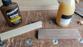
However, before we get onto that, I thought I'd do a quick test of some protein glues. I like the idea of using "traditional" (ish) glue on this project, partly because I've never used them before and this project is partly about practising new techniques, but also partly because they're supposedly reversible and that might be useful if I mess something up later!

Having never used them before, I thought I'd do a very simple first test just to see what they were like. I got a few offcuts, cut them up into short strips and glued them together, one pair with TB hide glue and one pair with fish glue.

glue_test.jpg

Both seem to have stuck very well and cleaned up nicely. The fish glue was much nicer to spread: the TB hide glue was very gloopy. I might do another test with them both after dunking the bottles in some warm water for a bit to see if that makes them a bit more spreadable.

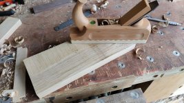
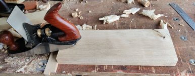
Anyway, back to the chestnut. The pieces I sawed up yesterday had one (machine) planed (by Wentwood timber) side and one very rough sawn side. For the rough sawn side I decided to do a quick pass with a (relatively) lightly set scrub plane. I'm not sure this saved any time, but it's quite fun and the scrub plane is nice to use as it's so much lighter than my metal planes.

scrub.jpg

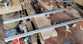
After that, it was back to old faithful (my Axminster #5) to plane the faces until they were flat and twist free (using a couple of bits of skip-found aluminium extrusion as winding sticks as usual):

winding.jpg

For most of the faces of most of the pieces, that was it. However, a few of the faces had some reversing grain, so I treated them either to a skim with a 40° bevelled (so 52° cutting angle) BU smoothing plane...

bu_smoothing.jpg

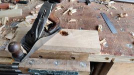
... or to a pass with a #4 with a back bevel of some angle I can't remember:

back_bevel_smoother.jpg

There were also a couple of faces that were really gnarly (I'm not sure whether these will make it into drawers yet given how messy the grain was) and they were treated to the wonderful get-out-of-jail-free card that is the scraper plane I bought from Mike Jordan of this parish:

scraper.jpg

Since I bought that from Mike, I've hardly touched the #80 cabinet scraper: the scraper plane is so easy to adjust for depth of cut and produces beautiful shavings and a lovely finish on pretty much anything I've thrown at it. Thanks for selling that to me Mike!

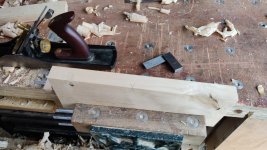
Once the two faces were flat and free of twist, I squared up one or both edges. The approach I took was to get one edge flat and square to one of the faces, then see whether it was also square to the other face. In some cases it was, in most cases it wasn't. On the ones where the edge wasn't square to the second face, I flipped the board over and planed the second edge square to the second face.

square_edge.jpg

Everything was marked accordingly so that when a face goes against the bandsaw fence, the edge that is square to that face can go against the bandsaw table. I'm sure I could just push hard against the fence and not worry too much about the edge on the table, but it felt like this would make things easier / safer.

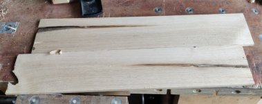
With that done, the last thing to do is mark thickness and then plane the sawn sides of each piece to thickness. I've done one plank's worth so far (the one with the big crack in it), so that leaves me 14 more pieces to plane to thickness. Once that's done, I'll figure out whether I've made enough pieces to do all the drawer sides and backs and then perhaps start planing the (thicker) pieces that will form the drawer fronts.

thin_strips.jpg
 
Back
Top