
-
Hi all and welcome to TheWoodHaven2 brought into the 21st Century, kicking and screaming! We all have Alasdair to thank for the vast bulk of the heavy lifting to get us here, no more so than me because he's taken away a huge burden of responsibility from my shoulders and brought us to this new shiny home, with all your previous content (hopefully) still intact! Please peruse and feed back. There is still plenty to do, like changing the colour scheme, adding the banner graphic, tweaking the odd setting here and there so I have added a new thread in the 'Technical Issues, Bugs and Feature Requests' forum for you to add any issues you find, any missing settings or just anything you'd like to see added/removed from the feature set that Xenforo offers. We will get to everything over the coming weeks so please be patient, but add anything at all to the thread I mention above and we promise to get to them over the next few days/weeks/months. In the meantime, please enjoy!
You are using an out of date browser. It may not display this or other websites correctly.
You should upgrade or use an alternative browser.
You should upgrade or use an alternative browser.
WIP for the New Year (Dun)
- Thread starter Woodbloke
- Start date

Woodbloke
Sequoia
Correct, but it's more than enough to just hold the door in position so that all that's required gentle pressure to open the door - RobMike G":1f9fv7qy said:If I've followed along correctly it's not a positive catch so much as a pressure plate pushing gently on the underside of the door. Is that right?
Cabinetman
Sequoia
- Joined
- Oct 11, 2020
- Messages
- 5,687
- Reaction score
- 1,367
- Location
- Lincolnshire Wolds + Massachusetts
- Name
- Ian
And as someone who has had a little play with previous iterations, I can say they are perfect for the job they have to do, as well as being really attractive. They also appeal to my "make something novel and better than you can buy" philosophy.
Ian
Ian
Cabinetman
Sequoia
- Joined
- Oct 11, 2020
- Messages
- 5,687
- Reaction score
- 1,367
- Location
- Lincolnshire Wolds + Massachusetts
- Name
- Ian
Without the elegance, and just wouldn’t feel right, it wouldn’t have the wood sliding on wood feel.
Woodbloke
Sequoia
Indeed, but to coin a term, t'would be 'fugly!' - RobMike G":qnyhkb0g said:So a magnet let into the underside of the door, and one let into the "floor" would achieve the same thing, but without the elegance.

Mike G
Petrified Pine
You could make it invisible by letting the floor magnet in from the underside of the floor to just under the surface of the wood, or let it in from the top and make a show off it with a contrasting plug. They hadn't yet discovered rare earth magnets in the 1950s.
GaryR
Nordic Pine
I just read through the thread and have really enjoyed seeing your techniques. I've file away several in my brain. Whether I can retrieve them when I need them is another matter.
Looking forward to the final reveal.
Looking forward to the final reveal.
Woodbloke
Sequoia
That's still an unnecessary faff IMO. There is a more helegant way of using magnets though. This is an elm cabinet I made some years ago, now home some of SWIMBO's stuff:Mike G":3bcsy5v0 said:You could make it invisible by letting the floor magnet in from the underside of the floor to just under the surface of the wood, or let it in from the top and make a show off it with a contrasting plug. They hadn't yet discovered rare earth magnets in the 1950s.

...where there are a set of drawers behind the doors; it was impossible to fit a catch of any sort to hold them, so I used a pair 8mm rare earth magnets:

...set just below the surface and covered with a patch of very, very thin, fine glove leather - Rob
Woodbloke
Sequoia
Having done all the necessary stuff on the interior of the cabinet, it needs to be finished prior to gluing. There are loads of different options which are all good, but firstly the joints were masked off:

I decided to apply several thin coats of Liberon Finishing Oil (simply as I had a new can of the stuff) using a rag as I can control how much is applied to the surface without getting any in the 3mm grooves. When the shelve assemblies are completed it'll also be much easier to finish them with oil before they're glued into the cabinet:
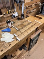
Four thin coats should do it which will be allowed to harden off overnight before the big glue up. Eventually, a coat of Chestnut Wood Wax will go over the top to finish - Rob
I decided to apply several thin coats of Liberon Finishing Oil (simply as I had a new can of the stuff) using a rag as I can control how much is applied to the surface without getting any in the 3mm grooves. When the shelve assemblies are completed it'll also be much easier to finish them with oil before they're glued into the cabinet:
Four thin coats should do it which will be allowed to harden off overnight before the big glue up. Eventually, a coat of Chestnut Wood Wax will go over the top to finish - Rob
Cabinetman
Sequoia
- Joined
- Oct 11, 2020
- Messages
- 5,687
- Reaction score
- 1,367
- Location
- Lincolnshire Wolds + Massachusetts
- Name
- Ian
Not being an oiler, I’m presuming that as you haven’t masked off the grooves the oil isn’t rubbed in much? So do you dab/wipe it on and wait for it to sink in, then start again?
Woodbloke
Sequoia
Correct Ian; just a thin rag applied coat which is easy to control. Downside is that it takes a while to dry before the next coat and definitely overnight before it's fully cured - RobCabinetman":3hmrvxte said:Not being an oiler, I’m presuming that as you haven’t masked off the grooves the oil isn’t rubbed in much? So do you dab/wipe it on and wait for it to sink in, then start again?
Woodbloke
Sequoia
The cabinet was glued this morning; thankfully not too irksome a task. The first thing to was use a small bit of ds tape to secure:

....some ply gluing blocks in place. I usually use hardwood if possible for this as pine tends to crush and disintegrate under the cramping pressure. Stuff was then assembled on the bench for cleaning; a kettle for very hot water, tub for said hot water, a stencil brush (an old cut down glue brush), clean rag and a knife bladed acrylic tool to get into corners if needed:

Glueing stuff was then assembled, a small paint brush for glue application, a silicone tray to hold said glue, a sash cramp and a couple of saddles to hold it steady:
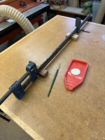
The pic shows the amount of glue used, which was very little. If the joints fit, you don't actually need a huge amount and using less rather than more makes removing any 'squeeze out' a doddle. Far too often I see YouToobers etc troweling the stuff on and it really isn't necessary, partly 'cos it's too damned expensive to waste:
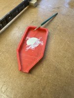
What remains in the tray was scooped up and put back into the D4 Everbuild bottle With just a smear of glue on the tails (none needed on the shoulder line sockets), the job was initially tapped together with a rubber maul and the cramp (singular) used to pull the joints together:

There's always a bit of squeaking and groaning as the joints pulls up, but as steady pressure is wound on the tails pulled right into the bottom of the sockets. As is sometimes seen, a large hammer is used to drive dovetails together; in my very 'umble opinion, a very poor way to do it as the joint is just subjected to a huge amount of shock. Much better to use a slow and steady squeeze with a sash cramp. This was the amount of 'squeeze out':
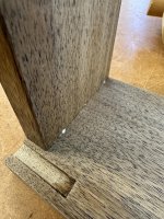
...on the inside and on the outside:
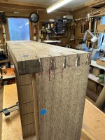
...there was a little more; the work of a few seconds to remove with hot water and a barely damp brush. The diagonals were then checked across the back (spot on):
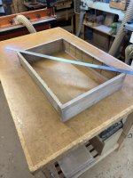
...and finally the long internal sides checked for 'wind'

...as this is eventually where the door will locate against the cabinet. Again, all good with no twist. Back next - Rob
....some ply gluing blocks in place. I usually use hardwood if possible for this as pine tends to crush and disintegrate under the cramping pressure. Stuff was then assembled on the bench for cleaning; a kettle for very hot water, tub for said hot water, a stencil brush (an old cut down glue brush), clean rag and a knife bladed acrylic tool to get into corners if needed:
Glueing stuff was then assembled, a small paint brush for glue application, a silicone tray to hold said glue, a sash cramp and a couple of saddles to hold it steady:
The pic shows the amount of glue used, which was very little. If the joints fit, you don't actually need a huge amount and using less rather than more makes removing any 'squeeze out' a doddle. Far too often I see YouToobers etc troweling the stuff on and it really isn't necessary, partly 'cos it's too damned expensive to waste:
What remains in the tray was scooped up and put back into the D4 Everbuild bottle
With just a smear of glue on the tails (none needed on the shoulder line sockets), the job was initially tapped together with a rubber maul and the cramp (singular) used to pull the joints together:There's always a bit of squeaking and groaning as the joints pulls up, but as steady pressure is wound on the tails pulled right into the bottom of the sockets. As is sometimes seen, a large hammer is used to drive dovetails together; in my very 'umble opinion, a very poor way to do it as the joint is just subjected to a huge amount of shock. Much better to use a slow and steady squeeze with a sash cramp. This was the amount of 'squeeze out':
...on the inside and on the outside:
...there was a little more; the work of a few seconds to remove with hot water and a barely damp brush. The diagonals were then checked across the back (spot on
):...and finally the long internal sides checked for 'wind'
...as this is eventually where the door will locate against the cabinet. Again, all good with no twist. Back next - Rob
Cabinetman
Sequoia
- Joined
- Oct 11, 2020
- Messages
- 5,687
- Reaction score
- 1,367
- Location
- Lincolnshire Wolds + Massachusetts
- Name
- Ian
That’s a good idea, I’ve used blocks on sash cramps before but not to keep the metal away from the joint like that. Last thing you want on the wood is a black mark, and spoils good Record cramps as well.
Now contention! I was trained not to use water when cleaning up as it will be taken into the joint by capillary action, so I never have, can’t say I’ve ever missed the water, but also can’t say if the capillary thing is true or not. Suspect it was just him being fussy, also would water displace thicker glue?
Ian
Now contention! I was trained not to use water when cleaning up as it will be taken into the joint by capillary action, so I never have, can’t say I’ve ever missed the water, but also can’t say if the capillary thing is true or not. Suspect it was just him being fussy, also would water displace thicker glue?
Ian


Dr.Al
Old Oak
AndyT":72vjawzq said:I certainly approve of the 'just enough' approach to glueing up.
Me too. I used to daub it on every surface when gluing up and then had loads of squeeze-out to deal with. Then I watched a David Charlesworth video where he advocated putting it just on the side grain (obvious when you think about it) and also only putting glue on the outer 50% (might have been 2/3rds) of the sides of the pins. The glue on the tails tends to get pushed to the outside of the joint whereas the glue on the pins gets pushed to the inside. By putting it only on the outer 50% of the pin, there's no squeeze-out at all on the inside of the box where it's hard to clean up; any squeeze-out on the outside is easy to clean (I usually rub plane shavings over it, which works rather well).
Edit: this isn't the video I was referring to, but he does a similar thing here: https://youtu.be/S0Nq58mYDBs?si=5Yhy6iyDOodTfVCB&t=126 (that link starts as he's gluing the pins for a secret mitre dovetail).
Woodbloke
Sequoia
You missed the salient point Ian. If you scroll back through wot I said, I mentioned writ bold that the brush is barely damp. The technique is to use scalding hot water, dip yonder brush into it and then remove most of the water with the clean rag. The clean up is then miraculous (most glue removed with the cloth) and was shown to me in a 'shop that made for Linely. Try it, it worksCabinetman":3s7lvun0 said:Now contention! I was trained not to use water when cleaning up as it will be taken into the joint by capillary action, so I never have, can’t say I’ve ever missed the water, but also can’t say if the capillary thing is true or not. Suspect it was just him being fussy, also would water displace thicker glue?
Ian
- RobCabinetman
Sequoia
- Joined
- Oct 11, 2020
- Messages
- 5,687
- Reaction score
- 1,367
- Location
- Lincolnshire Wolds + Massachusetts
- Name
- Ian
Yep missed that little detail. Good
Woodbloke
Sequoia
Yesterday I took the big LV try and trued up the back:

...and then used a half decent 600mm edge to check it for straightness:
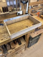
I can use the proper winding strips to check if it's true across the corners, but:

...I usually plonk these things down on the ci router table top and if it sits flat without wobbling, 'tis good enough. I then needed to work out the depth of the rebate; I had 2mm thick walnut, 4mm ply and some odds n'sods of 2mm thick ash as a backer and if my sums were correct, that made 8mm. The plan though, is to use some of these No.4 brass screws:
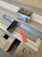
...to go through the back and into the centre of each shelf assembly to support it. The pic shows that 10mm of the thread will go into the shelf backs, which seems about right. Just to check to see if the thread would go into something 6mm thick I did a little trial...not the same screws but the same dia:

A 2mm pilot drill seemed to do the job and I always lube the threads with a smear of Vaseline. The big Festool router was set up with bearing guided cutter for a doc of 8mm (using the brass gauge blocks) and my super wide pine base bolted onto the underside:

This means that making a rebate in a cabinet back is a walk in the park, provided that the extended base is always in contact with the cabinet each side of the router; if it's not there's big trouble!
It took about five minutes to machine the rebate and once done, the corners needed to be squared out with a large chisel:
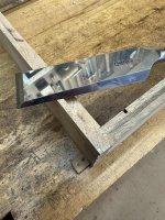
....which is a job for tomorrow - Rob
...and then used a half decent 600mm edge to check it for straightness:
I can use the proper winding strips to check if it's true across the corners, but:
...I usually plonk these things down on the ci router table top and if it sits flat without wobbling, 'tis good enough. I then needed to work out the depth of the rebate; I had 2mm thick walnut, 4mm ply and some odds n'sods of 2mm thick ash as a backer and if my sums were correct, that made 8mm. The plan though, is to use some of these No.4 brass screws:
...to go through the back and into the centre of each shelf assembly to support it. The pic shows that 10mm of the thread will go into the shelf backs, which seems about right. Just to check to see if the thread would go into something 6mm thick I did a little trial...not the same screws but the same dia:
A 2mm pilot drill seemed to do the job and I always lube the threads with a smear of Vaseline. The big Festool router was set up with bearing guided cutter for a doc of 8mm (using the brass gauge blocks) and my super wide pine base bolted onto the underside:
This means that making a rebate in a cabinet back is a walk in the park, provided that the extended base is always in contact with the cabinet each side of the router; if it's not there's big trouble!
It took about five minutes to machine the rebate and once done, the corners needed to be squared out with a large chisel:
....which is a job for tomorrow - Rob

Blackswanwood
Old Oak
As ever, a great thread Rob. That method of routing the rebate is a really neat way of doing it ... and obvious now it's been pointed out!
Cabinetman
Sequoia
- Joined
- Oct 11, 2020
- Messages
- 5,687
- Reaction score
- 1,367
- Location
- Lincolnshire Wolds + Massachusetts
- Name
- Ian
Yes that long base trick is a goody, Ian
Woodbloke
Sequoia
Having squared out the corners on the cabinet rebate, the ply back was roughly cut to about 10mm oversize, then I started on the veneer 'lay-ups' (technical term for joining the veneers together ) First up was to cramp my dedicated veneer shooter to the assembly bench:

...onto which 'Big Woody' runs. The veneer shoot is nothing super accurate, just two bits of Contiboard screwed together, with a runway for the plane. Any plane with a decent length sole will do but obviously the longer, the better. Big Woody has a greenheart sole (with adjustable mouth) much longer than a No.8 with a 6mm thick iron supplied by our very own Philly Planes :eusa-dance:
I started on the Walnut by shooting one end square as it prevents wobbling as the edge is shot in:

I should add at this point that all the veneers were cut on the bandsaw and thicknessed on the Jet drum sander down to 2mm. It's not absolutely necessary for a sander, but once you've got one, it's a complete game changer for this sort of malarky and makes the whole job much easier and far more predictable for a decent outcome. All the veneers (show face and back) were shot in with one side reversed so that any slight deviations from square in BW's blade would be cancelled out. When they're offered up together, they should fit together snugly; any high spot will make the joint 'rock' so a shaving or two is taken until they fit. Tape is then used to pull the joint(s) together; it's absolutely essential that a really, top drawer tape is used such as Scotch or Tesa. Don't even think about using your bog standard el cheapo 'shop masking tape 'cos that way lies doom!
I start the taping on:

...one side only of the joint and using a SS roller to make sure it's really, really stuck; note that the veneer is held firmly against the shooting board. Then the other half can be stretched quite a lot (at least 4-6mm here) to pull up the joint, after which it's rolled. Then I work my way all the way along the joint placing a bit of tape every 100mm or so:
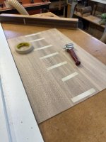
The joint is finished with a strip of proper 'licky' paper veneer tape which is good stuff as it shrinks as it drys and pulls the joint even tighter together:

...which is again rolled to ensure it's fully stuck.
The balancer veneers were next which was a bit more of a faff as there were eight narrow strips to join together:

I added an additional little fence to the shooter to hold the Ash sections in the right place as past experience has taught me that planing narrow bits like this is a bit awkard; this addition makes it much easier:

The Ash backers were planed in exactly the same way as detailed above, but when the Scotch tape was used a single bit was pulled across all eight pieces and I estimate it stretched about 30mm :shock: It can be pulled with a lot of force and the stuff won't snap, but it may 'give way' if the initial stick on the first bit isn't good enough. The joints were again:
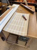
...taped with paper veneer tape and then the 'lay up' was trimmed to size - Rob
) First up was to cramp my dedicated veneer shooter to the assembly bench:...onto which 'Big Woody' runs. The veneer shoot is nothing super accurate, just two bits of Contiboard screwed together, with a runway for the plane. Any plane with a decent length sole will do but obviously the longer, the better. Big Woody has a greenheart sole (with adjustable mouth) much longer than a No.8 with a 6mm thick iron supplied by our very own Philly Planes :eusa-dance:
I started on the Walnut by shooting one end square as it prevents wobbling as the edge is shot in:
I should add at this point that all the veneers were cut on the bandsaw and thicknessed on the Jet drum sander down to 2mm. It's not absolutely necessary for a sander, but once you've got one, it's a complete game changer for this sort of malarky and makes the whole job much easier and far more predictable for a decent outcome. All the veneers (show face and back) were shot in with one side reversed so that any slight deviations from square in BW's blade would be cancelled out. When they're offered up together, they should fit together snugly; any high spot will make the joint 'rock' so a shaving or two is taken until they fit. Tape is then used to pull the joint(s) together; it's absolutely essential that a really, top drawer tape is used such as Scotch or Tesa. Don't even think about using your bog standard el cheapo 'shop masking tape 'cos that way lies doom!
I start the taping on:
...one side only of the joint and using a SS roller to make sure it's really, really stuck; note that the veneer is held firmly against the shooting board. Then the other half can be stretched quite a lot (at least 4-6mm here) to pull up the joint, after which it's rolled. Then I work my way all the way along the joint placing a bit of tape every 100mm or so:
The joint is finished with a strip of proper 'licky'
paper veneer tape which is good stuff as it shrinks as it drys and pulls the joint even tighter together:...which is again rolled to ensure it's fully stuck.
The balancer veneers were next which was a bit more of a faff as there were eight narrow strips to join together:
I added an additional little fence to the shooter to hold the Ash sections in the right place as past experience has taught me that planing narrow bits like this is a bit awkard; this addition makes it much easier:
The Ash backers were planed in exactly the same way as detailed above, but when the Scotch tape was used a single bit was pulled across all eight pieces and I estimate it stretched about 30mm :shock: It can be pulled with a lot of force and the stuff won't snap, but it may 'give way' if the initial stick on the first bit isn't good enough. The joints were again:
...taped with paper veneer tape and then the 'lay up' was trimmed to size - Rob
Woodbloke
Sequoia
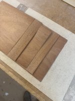
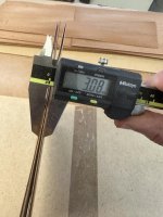
I decided that the 3mm ply was going to go into the vac bag at the same time as the back panel, so 5 @ 0.6mm mahogany veneers were sliced up:
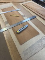
There's quite often some online discussion about the most dangerous tool in the 'shop, but there's absolutely no question in my mind that it's a Stanley knife with a new blade, especially when it's used with an ordinary, thin steel rule. I've been to A&E twice when the knife jumped the rule and went straight across my thumb; I still have the scars on my lh thumb to bear witness. I now only ever use the thick edge of Maun straight edge for cutting veneers.
This is the stuff needed for glueing the 'lay-ups':

I decided not to use the small Gluebot as it was virtually empty; the black speader was dropped into the water jar as soon as the glue's been adequately spread. Starting with the Ash back, the first joint was hung over the edge of the bench:

...and a smear of TB3 run down the joint on the two veneer edges....all joints glued in the pic. The face walnut lay-up was treated in the same way and then glue was applied to the substrate only, making sure that there's a decent coverage, inc the all important edges. The lay-ups were quickly assembled and then nudged into position, bearing in mind that there's plenty of waste at the sides to be trimmed off later. Once it's about right, copious amounts of masking tape:

...were used at the corners and sides to hold everything in more or less the right place before it's placed in the vac bag, after which it's sealed and the suckage applied:
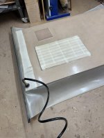

When the dial needle hits the buffers it's pulling a full vacuum; also shown in the bag is the 3mm plywood being glued. After a couple of hours, both bits were extracted from the bag; the tape can be easily lifted with water, a sponge and a cabinet scraper. This can't be done if a non-waterproof glue (eg TB1) is used as the veneer will lift! Don't ask me how I know :eusa-doh: :eusa-doh:
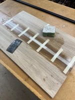
Unfortunately for reasons best known to itself, the mahogany veneers refused to glue together in the vac bag, so they were left overnight:
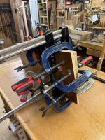
...between cauls with a bunch of cramps on, which seemed to do the trick when I took them off this morning. Once all the old tape and general grunge was cleaned of the walnut:
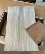
..the glue joint is all but invisible (as it should be) but it's easy to tell there are two book matched veneers because of the grain pattern. Were they to be slip matched, it would appear to be a continuous sheet of walnut as the joints can't be seen. Working from the walnut joint line, the panel has also been marked out and the waste cut off so there's about 6mm or so left for fitting later into the rebate - Rob
There's quite often some online discussion about the most dangerous tool in the 'shop, but there's absolutely no question in my mind that it's a Stanley knife with a new blade, especially when it's used with an ordinary, thin steel rule. I've been to A&E twice when the knife jumped the rule and went straight across my thumb; I still have the scars on my lh thumb to bear witness. I now only ever use the thick edge of Maun straight edge for cutting veneers.
This is the stuff needed for glueing the 'lay-ups':
I decided not to use the small Gluebot as it was virtually empty; the black speader was dropped into the water jar as soon as the glue's been adequately spread. Starting with the Ash back, the first joint was hung over the edge of the bench:
...and a smear of TB3 run down the joint on the two veneer edges....all joints glued in the pic. The face walnut lay-up was treated in the same way and then glue was applied to the substrate only, making sure that there's a decent coverage, inc the all important edges. The lay-ups were quickly assembled and then nudged into position, bearing in mind that there's plenty of waste at the sides to be trimmed off later. Once it's about right, copious amounts of masking tape:
...were used at the corners and sides to hold everything in more or less the right place before it's placed in the vac bag, after which it's sealed and the suckage applied:
When the dial needle hits the buffers it's pulling a full vacuum; also shown in the bag is the 3mm plywood being glued. After a couple of hours, both bits were extracted from the bag; the tape can be easily lifted with water, a sponge and a cabinet scraper. This can't be done if a non-waterproof glue (eg TB1) is used as the veneer will lift! Don't ask me how I know :eusa-doh: :eusa-doh:
Unfortunately for reasons best known to itself, the mahogany veneers refused to glue together in the vac bag, so they were left overnight:
...between cauls with a bunch of cramps on, which seemed to do the trick when I took them off this morning. Once all the old tape and general grunge was cleaned of the walnut:
..the glue joint is all but invisible (as it should be) but it's easy to tell there are two book matched veneers because of the grain pattern. Were they to be slip matched, it would appear to be a continuous sheet of walnut as the joints can't be seen. Working from the walnut joint line, the panel has also been marked out and the waste cut off so there's about 6mm or so left for fitting later into the rebate - Rob
Woodbloke
Sequoia
The back was fitted snugly with out too much hassle and I then made up a prototype shelf assembly in 6mm pine with a couple of 3mm thick ply inserts for the joints. I usually do this with any part of a project which is a bit suspect; in this case I was unsure if a shelf assembly would slide into the housing without falling apart:
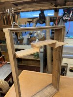
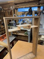
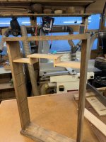
This prototype assembly slid in smoothly (dry, no glue) and I even replicated the back with a gash piece of pine across the rebate and screwed it without a problem into the shelf back. Next job is to build all the shelf assemblies in walnut, polish each and then glue them into the cabinet - Rob
This prototype assembly slid in smoothly (dry, no glue
) and I even replicated the back with a gash piece of pine across the rebate and screwed it without a problem into the shelf back. Next job is to build all the shelf assemblies in walnut, polish each and then glue them into the cabinet - Rob
Woodbloke
Sequoia
Yep, that thought had occurred Mike but there was no need in the end. The little housed joints are surprisingly robust once the glue's gone off - RobMike G":1unshbh0 said:Not sure why you'd worry about its strength, Rob. You could easily screw a scrap of ply as a brace across the back, and unscrew it once everything was permanently in place.
Woodbloke
Sequoia
Update on this one. After much faffing and fiddling, which included cutting numerous small dovetails and machining housing joints on the router table, all the 'stepped' shelves have been glued into place:
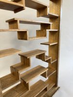

I used fast setting epoxy in the end as it enabled the shelves to be tapped home relatively easily without the 'grab' that occurs with TB3 and similar glues. Once the glue had set on the last shelf, I used the router with it's very wide base to machine off anything that was a bit proud, so fingers crossed, all the shelf backs should be level with the rebate:

Much faffing yet to do on the interior before the back is fitted and glued in place. The shelves will be additionally supported by No.4 brass screws - Rob
I used fast setting epoxy in the end as it enabled the shelves to be tapped home relatively easily without the 'grab' that occurs with TB3 and similar glues. Once the glue had set on the last shelf, I used the router with it's very wide base to machine off anything that was a bit proud, so fingers crossed, all the shelf backs should be level with the rebate:
Much faffing yet to do on the interior before the back is fitted and glued in place. The shelves will be additionally supported by No.4 brass screws - Rob


Malc2098":4jphtqbo said:Nice job.
Darn clever too. Calling this thread just “shelves” does the project an injustice.
Andyp":9s35n9in said:Malc2098":9s35n9in said:Nice job.
Darn clever too. Calling this thread just “shelves” does the project an injustice.
Quite so. Where are the wonky metal brackets?

Woodbloke
Sequoia
You mean the small metal shelf brackets from one of the sheds? :lol: I thought I'd pass on those for this job!AndyT":1x2y8h6x said:Andyp":1x2y8h6x said:Malc2098":1x2y8h6x said:Nice job.
Darn clever too. Calling this thread just “shelves” does the project an injustice.
Quite so. Where are the wonky metal brackets?
Once I'd got into the routine of making them, they weren't too bad. The trick was to work out the correct sequence to machine the housings and then assemble and glue each one, making sure that as far as possible each of the dovetail/housing sections was square as it set.
Finished with a few coats of Liberon 'Finishing Oil' with some wax over the top. Loads more cleaning up on the interior to do, but with the back on 'dry' and unpolished (pilot holes already drilled):

...you can get an idea of what it'll eventually look like. The top of the lower door rail will be level with the shelf so the JK door catch won't be seen. It's been brought inside so SWIMBO can cast a beady eye over it when she gets in from work - Rob
Woodbloke
Sequoia
Thanks; that's exactly what I did...a 1:1 full size drawing. I forget to check it though when I glued the second shelf (from the top) in upside down! :eusa-doh: :eusa-doh: Got it sorted though and it's now the right way up :eusa-dance: - RobPAC1":2vn132en said:It is looking very good. I would have needed a full size drawing to reference every 2 minutes with a build like that.
fiveeyes
Sapling
That is really nice. Like that a lot!!  bscene-drinkingcheers:
bscene-drinkingcheers:Cabinetman
Sequoia
- Joined
- Oct 11, 2020
- Messages
- 5,687
- Reaction score
- 1,367
- Location
- Lincolnshire Wolds + Massachusetts
- Name
- Ian
Hi Rob, that looks fantastic, I really like the way you’ve designed the layout of the shelves, only thing I can see and it might be the camera, 2nd shelf up on the left is slightly out of level? IF it is it’s easy to fix with aforementioned brass screws I suppose.
Ian
Ian
Woodbloke
Sequoia
It's the camera I think Ian; I've just checked and they're all level. When I sight across from one side to the other, the lh side shelf is in line with it's counterpart on the rh side, with no one side being slightly up or down.Cabinetman":1byk7ccm said:Hi Rob, that looks fantastic, I really like the way you’ve designed the layout of the shelves, only thing I can see and it might be the camera, 2nd shelf up on the left is slightly out of level? IF it is it’s easy to fix with aforementioned brass screws I suppose.
Ian
The most important thing is that my accumulated brownie points are now fully topped up! :lol: :lol: - Rob
Cabinetman
Sequoia
- Joined
- Oct 11, 2020
- Messages
- 5,687
- Reaction score
- 1,367
- Location
- Lincolnshire Wolds + Massachusetts
- Name
- Ian
Well I did think it unlikely!

Phil
Old Oak
Nice, very smart! 
Woodbloke
Sequoia
The door's now made and fitted tightly to the opening, slightly (by design) oversize in the width. The back's also oiled and fitted but screwed this time rather than glued:

The next job is to plane it to width and then produce the 'shadow gaps' top and bottom, after which comes the hinge fitting and that's always a ticklish business; slow and steady in the name of the game :eusa-whistle:
Much faffing still to do, such as the fitting the JK door catch, the 'button' at the top on the underside, then door handle, glazing, making the glazing bars and the mild steel 'keyhole' brackets for mounting to the wall - Rob
The next job is to plane it to width and then produce the 'shadow gaps' top and bottom, after which comes the hinge fitting and that's always a ticklish business; slow and steady in the name of the game :eusa-whistle:
Much faffing still to do, such as the fitting the JK door catch, the 'button' at the top on the underside, then door handle, glazing, making the glazing bars and the mild steel 'keyhole' brackets for mounting to the wall - Rob