
-
Hi all and welcome to TheWoodHaven2 brought into the 21st Century, kicking and screaming! We all have Alasdair to thank for the vast bulk of the heavy lifting to get us here, no more so than me because he's taken away a huge burden of responsibility from my shoulders and brought us to this new shiny home, with all your previous content (hopefully) still intact! Please peruse and feed back. There is still plenty to do, like changing the colour scheme, adding the banner graphic, tweaking the odd setting here and there so I have added a new thread in the 'Technical Issues, Bugs and Feature Requests' forum for you to add any issues you find, any missing settings or just anything you'd like to see added/removed from the feature set that Xenforo offers. We will get to everything over the coming weeks so please be patient, but add anything at all to the thread I mention above and we promise to get to them over the next few days/weeks/months. In the meantime, please enjoy!
You are using an out of date browser. It may not display this or other websites correctly.
You should upgrade or use an alternative browser.
You should upgrade or use an alternative browser.
Garden Table
- Thread starter Dr.Al
- Start date

Dr.Al
Old Oak
Compact is a bit of an understatement!Btw I do like how your work area is quite compact.

Dr.Al
Old Oak
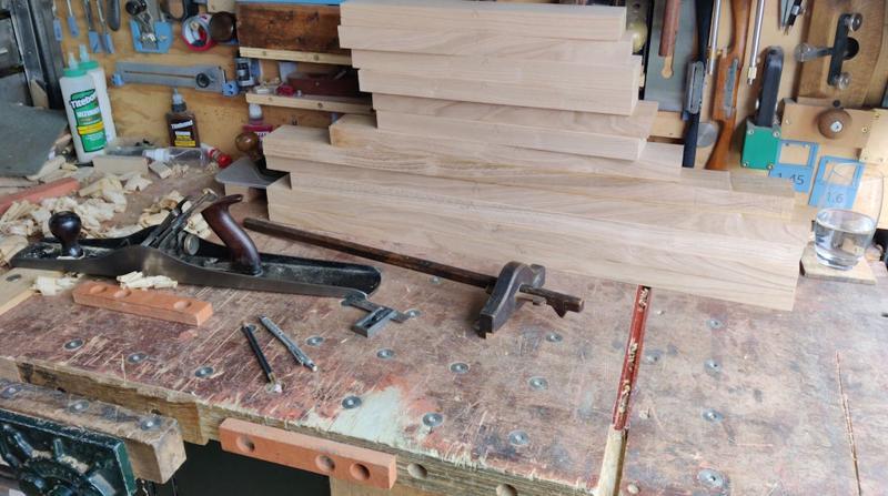
Just a quick update today. I've been gradually working my way through some more sweet chestnut, turning it into a large pile of equal-ish sized planks, planed on all four sides:
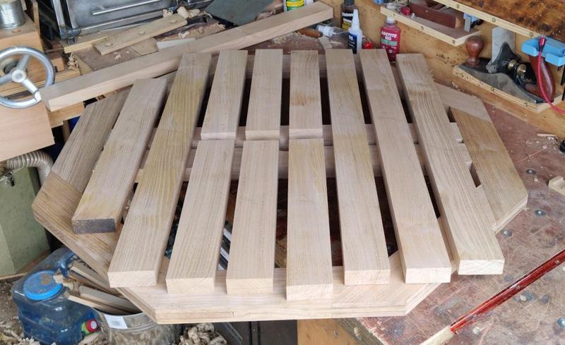
With all the bits dimensioned, I could lay them onto the table in about the right place to get an idea of how it might look:
The next job is going to be to start cutting the half-lap dovetails to fit the slats into the frame. I'm pretty sure I know how I'm going to do that for the central slats, but the ones towards the edges need a bit more thought because of the angled end. I thought I'd do a drawing to see if I could get my head round it:
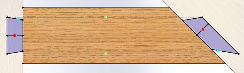
Does that look reasonable? I've made the length of the outer edge of the angled dovetail be such that the tips are in-line with the tips of the normal dovetail (controlled in the CAD model by the lines with the pale green dots). I've then made the two angled edges parallel with those at the other end (e.g. the two lines marked with a cyan dot are parallel). Finally, I've made the depth of the dovetails equal (controlled by the lines with the red dots).
Obviously it won't be that perfectly matched when I do it for real, but I just wanted to check that the general shape looked sensible: any thoughts?
With all the bits dimensioned, I could lay them onto the table in about the right place to get an idea of how it might look:
The next job is going to be to start cutting the half-lap dovetails to fit the slats into the frame. I'm pretty sure I know how I'm going to do that for the central slats, but the ones towards the edges need a bit more thought because of the angled end. I thought I'd do a drawing to see if I could get my head round it:
Does that look reasonable? I've made the length of the outer edge of the angled dovetail be such that the tips are in-line with the tips of the normal dovetail (controlled in the CAD model by the lines with the pale green dots). I've then made the two angled edges parallel with those at the other end (e.g. the two lines marked with a cyan dot are parallel). Finally, I've made the depth of the dovetails equal (controlled by the lines with the red dots).
Obviously it won't be that perfectly matched when I do it for real, but I just wanted to check that the general shape looked sensible: any thoughts?

The bottom right hand corner of the oblique dovetail looks a bit "sharp" to me. You risk having an area of short grain which could split off.
Yours is an unusual case, not one I've seen discussed, but it's similar to cutting dovetails on a drawer with a sloping front. I'll see if I can find a picture when I've finished this cup of tea
Yours is an unusual case, not one I've seen discussed, but it's similar to cutting dovetails on a drawer with a sloping front. I'll see if I can find a picture when I've finished this cup of tea

Malc2098
Sequoia
Hmm. I think I agree with Andy, above.
My eyes seem to think the angled dovetail should protrude from the end with it's tail top perpendicular to the length of the board. I think I'd prefer to see the tops of the two dovetails parallel to each-other, rather than the angled dovertail parallel to the angle of the end.
But, it's a taste thing, and how our eyes and brains perceive combinations of angles.
My eyes seem to think the angled dovetail should protrude from the end with it's tail top perpendicular to the length of the board. I think I'd prefer to see the tops of the two dovetails parallel to each-other, rather than the angled dovertail parallel to the angle of the end.
But, it's a taste thing, and how our eyes and brains perceive combinations of angles.
Dr.Al
Old Oak
Having thought about it and looked in some books, I think I have found expert advice on two opposing approaches. But do bear in mind that canted front drawers wouldn't be as extreme as your 45 degree octagon joints.
Ernest Joyce says, in The Technique of Furniture Making,
"If one piece is canted as in a drawer front, the dovetails must not be set out at right angles to the cant but equal either side of a line drawn parallel to the long edge, or weak grain will result and loosen the joint."
But in Dovetails the Hand Tool Approach, Mitch Peacock says:
"As the slope angle increases, the tails marked with a dovetail marking gauge will be rotated in relation to the tailboard grain direction. Consequently the tails become weaker and more liable to fail. A stronger and more pleasing layout is achieved by angling the tails as though the end of the tailboard were square to the sides."
I think that's the opposite way round from what Joyce says but I'm now confused myself. And I think both books are short of an illustration to make it any clearer.
So I don't think that's much help - sorry.
Is it too late to switch to nice, invisible, mortise and tenon joints?
Overall, I think your diagram shows the best compromise available. There's plenty of strength in the chestnut and no great strain on the joints.
Ernest Joyce says, in The Technique of Furniture Making,
"If one piece is canted as in a drawer front, the dovetails must not be set out at right angles to the cant but equal either side of a line drawn parallel to the long edge, or weak grain will result and loosen the joint."
But in Dovetails the Hand Tool Approach, Mitch Peacock says:
"As the slope angle increases, the tails marked with a dovetail marking gauge will be rotated in relation to the tailboard grain direction. Consequently the tails become weaker and more liable to fail. A stronger and more pleasing layout is achieved by angling the tails as though the end of the tailboard were square to the sides."
I think that's the opposite way round from what Joyce says but I'm now confused myself. And I think both books are short of an illustration to make it any clearer.
So I don't think that's much help - sorry.
Is it too late to switch to nice, invisible, mortise and tenon joints?
Overall, I think your diagram shows the best compromise available. There's plenty of strength in the chestnut and no great strain on the joints.
Last edited:
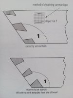
Here's a picture from Jim Kingshott, A Woodworker's Guide to Joints.
He's writing about double bevels on a hopper, but this side view is analogous and I think it's much clearer than just words.
So you were right all along
He's writing about double bevels on a hopper, but this side view is analogous and I think it's much clearer than just words.
So you were right all along
Dr.Al
Old Oak
Thanks @AndyT
I've read those a couple of times (and also consulted my copy of Joyce in case the nearby pictures helped me at all) and I think (but am happy to be corrected) that they're all saying the same thing and that the way I did it in both of the above drawings is correct (either the one with the angled end or the one with the parallel end). I'll try to justify that...
I think this is saying that the angles should be set out with respect to the centre line. In other words, the key angles (9.46° in this drawing: equivalent to 1:6) are the ones that are greyed out on the right: the angles from the dovetail sides to the centre line.
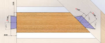
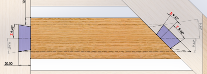
Whereas if you don't follow his advice and work off the canted angle, then you end up with the two red/black angles in the drawing and the dovetail looks like this (which is clearly wrong):
That doesn't, of course, help with deciding what to do with the end!
Again, I think this is talking about making sure that the angle is referenced off the centre line rather than the end of the board, so I think he's saying the same thing as Joyce.
This all seems to also tally with the pictures from Jim Kingshott (I haven't heard of that book, is it good?)
The only angled half-lap joint I've been able to find is one mentioned in Charles Hayward's "Woodwork Joints" and described as a "strong form of oblique halving":
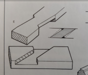
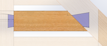
That's not quite the same, but it did get me thinking that one way to avoid the sharp tip might be simply to cut it off:
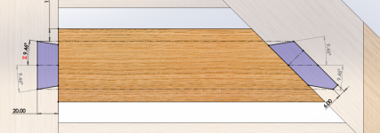
I've read those a couple of times (and also consulted my copy of Joyce in case the nearby pictures helped me at all) and I think (but am happy to be corrected) that they're all saying the same thing and that the way I did it in both of the above drawings is correct (either the one with the angled end or the one with the parallel end). I'll try to justify that...
Ernest Joyce said:"If one piece is canted as in a drawer front, the dovetails must not be set out at right angles to the cant but equal either side of a line drawn parallel to the long edge, or weak grain will result and loosen the joint."
I think this is saying that the angles should be set out with respect to the centre line. In other words, the key angles (9.46° in this drawing: equivalent to 1:6) are the ones that are greyed out on the right: the angles from the dovetail sides to the centre line.
Whereas if you don't follow his advice and work off the canted angle, then you end up with the two red/black angles in the drawing and the dovetail looks like this (which is clearly wrong):
That doesn't, of course, help with deciding what to do with the end!
Mitch Peacock said:"As the slope angle increases, the tails marked with a dovetail marking gauge will be rotated in relation to the tailboard grain direction. Consequently the tails become weaker and more liable to fail. A stronger and more pleasing layout is achieved by angling the tails as though the end of the tailboard were square to the sides."
Again, I think this is talking about making sure that the angle is referenced off the centre line rather than the end of the board, so I think he's saying the same thing as Joyce.
This all seems to also tally with the pictures from Jim Kingshott (I haven't heard of that book, is it good?)
The only angled half-lap joint I've been able to find is one mentioned in Charles Hayward's "Woodwork Joints" and described as a "strong form of oblique halving":
That's not quite the same, but it did get me thinking that one way to avoid the sharp tip might be simply to cut it off:
Dr.Al
Old Oak
Anyone else have any thoughts on this:

(or the same without the corner chopped off) vs this:

?
Or for that matter, any suggestions for other alternatives I haven't considered? "Nice, invisible, mortise and tenon joints" are not an option unless anyone has a magic formula for cleanly undoing 12 big Titebond 3 joints at the same time!
(or the same without the corner chopped off) vs this:
?
Or for that matter, any suggestions for other alternatives I haven't considered? "Nice, invisible, mortise and tenon joints" are not an option unless anyone has a magic formula for cleanly undoing 12 big Titebond 3 joints at the same time!
Malc2098
Sequoia
Yes.@AndyT Thanks, that picture would be useful!
@Malc2098 Also thanks! Just to clarify, do you mean you prefer it like this?
View attachment 33295
Having seen your drawing now, I might even change the long angle for parallel with the piece.
I thin I'd need to see the top of the table as a whole, to see what my eye would prefer. I don't thin it will affect the strength of the joint.
spb
Nordic Pine
Definitely the first one, without the corner chopped off, for me. The tail in the second one just looks weird.
Another thing I've seen done is to shift the tail angles just slightly, so that they're not quite identical relative to the edges, and not close to being identical relative to the joint line, but somewhere between the two. That way it looks more balanced to the eye, even if there's no actual logic to derive the angles.
Another thing I've seen done is to shift the tail angles just slightly, so that they're not quite identical relative to the edges, and not close to being identical relative to the joint line, but somewhere between the two. That way it looks more balanced to the eye, even if there's no actual logic to derive the angles.
It's https://en.wikipedia.org/wiki/Special:BookSources?isbn=9781558217775 - and unfortunately seems to have got silly expensive thanks to scarcity / automated pricing algorithms.This all seems to also tally with the pictures from Jim Kingshott (I haven't heard of that book, is it good?)
I'd say it's a good read and works as a companion to his long, informative videos that used to be sold on DVD but are now on YouTube eg
and
but not essential if you watch those carefully, or take notes.
No book on woodwork joints can ever hope to be comprehensive though, which is ok for those of us who also enjoy building bookcases!

An hour on the high seas pleasantly passed watching that DT vid. Thank you.
Can’t work out how to cut that joint seen in the 30 seconds though
Can’t work out how to cut that joint seen in the 30 seconds though
Dr.Al
Old Oak
Thanks all, I'll digest all that (and watch the videos when I get a mo) and try to come to a decision before I start cutting the angled pieces. At the end of the day, it'll all be on the underside of the table anyway, so hopefully it won't matter that much either way.
Dr.Al
Old Oak
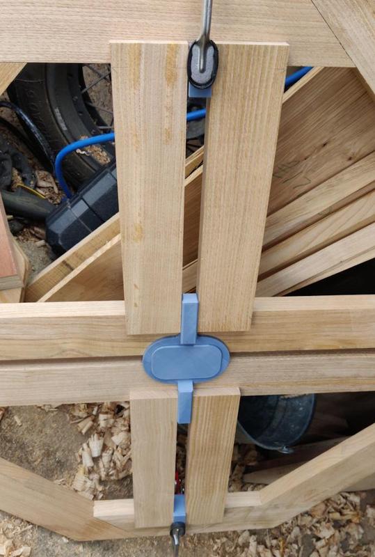
While still pondering the dovetail shape for the angled pieces, I thought I'd get on with the simpler ones. Overnight, I 3D-printed a little guide to help make sure the central slats would be evenly spaced around the central hole. The guide peg is circular but with some bits sticking out the side (imagine the London Underground logo): the circular part fits in the parasol hole; the bits sticking out the side ensures it stays square with the gap between the cross-bars. It then has a block that is sized to hopefully result in the slats being evenly spaced; I also printed a few simpler blocks with the (hopefully) correct spacing to help align the outer edge:
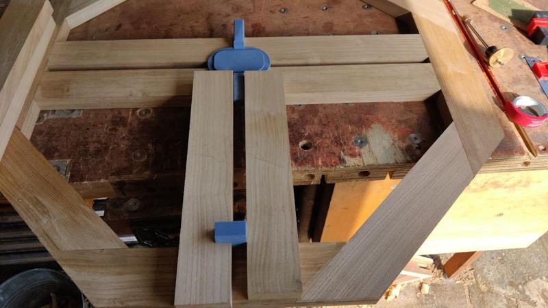
With those in place, I could clamp the planks to the table and mark the shoulder position with a knife. I could then transfer that line most of the way around each edge, just leaving a bit of a gap on the face that would end up on the underside of the table:
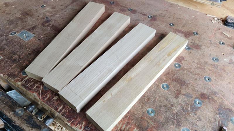
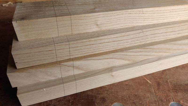
A steel rule was used to mark a position about 20 mm out from those knife lines (for the end of the dovetail) and that was also knifed all the way around (on both ends of the board):
On the first board, I created a knife wall with a chisel...
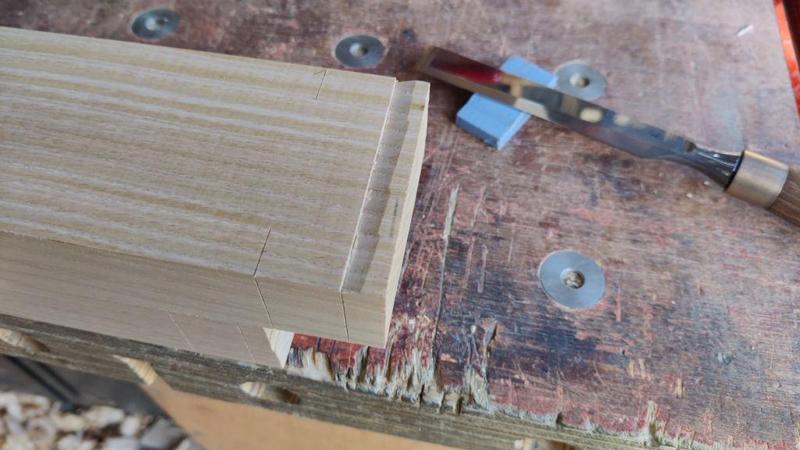
... and then sawed in the knife wall directly, figuring that the position didn't need to be super accurate (as I'd be cutting the slot to match) so I might as well saw straight to the line::
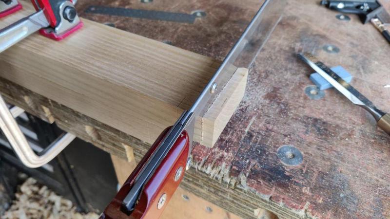
However, that left a little bit that needed to be pared away (as the saw hadn't cut **quite** to the knife line) so on the subsequent ones I just sawed to (roughly) the knife line and then gave each board a few passes on the shooting board to square up the ends. Only a relatively small proportion of the end needs to be square, but the shooting board seemed to me to be the quickest way to give a nice reference surface.
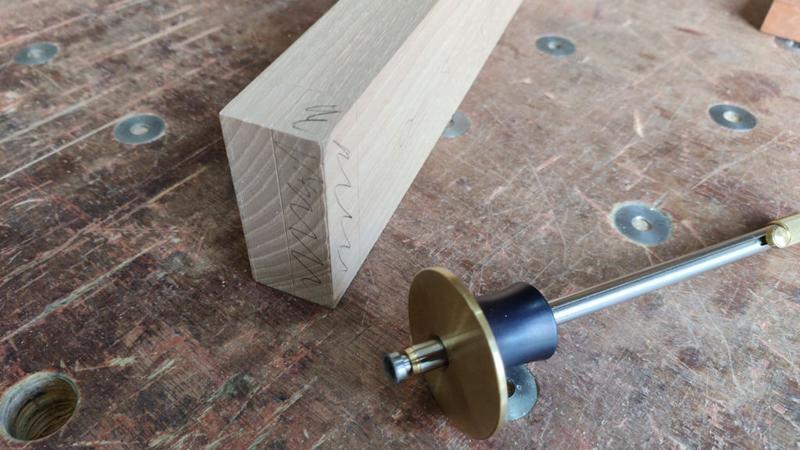
I set up a marking gauge for the depth of the lap joint and, while I was at it, I also set up one of my router planes to be cutting in that marking gauge line when referenced off the face side.
To cut the lap, I used a cross-cut Dozuki to cut a millimetre or so from the line...
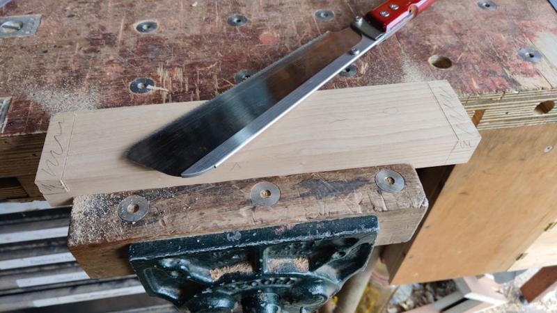
... and then a rip Dozuki to cut a millimetre or so away from the other line:
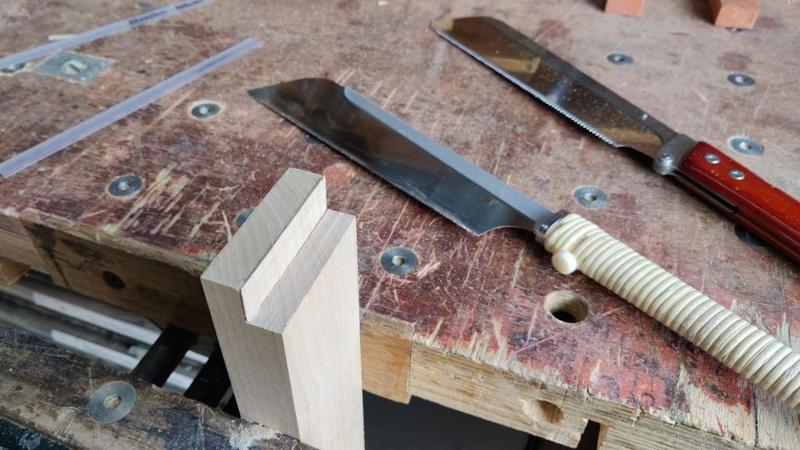
I've heard a few people say that this sort of joint should be done by sawing directly to the line, but that is a lot more risky and, more significantly in my opinion, would remove the step that involves using my two favourite tools, a chisel and a router plane (or in this case two router planes):
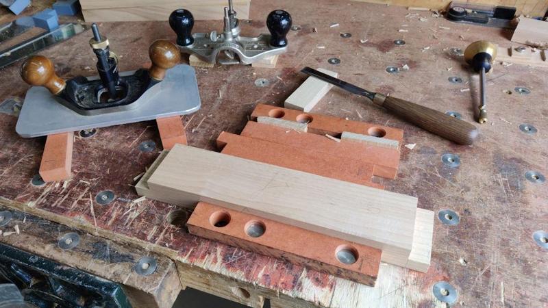
The chisel was used to trim the shoulder lines; the router planes were used for the cheeks. I had set the Stanley one up to cut exactly on the marking gauge line. The Veritas one (which has a much better depth stop) had its depth stop set such that it would cut very slightly above the gauge line, so I could use the Veritas one to rough out the cheek, taking three or four passes to get down to the depth stop. The Stanley one then did the final pass to get it perfect.
I could have just set the depth stop on the Veritas one for the gauge line, but using the second router plane just means I didn't have to worry about any possible slipping of the depth stop.
With that done, I could do a quick test fit:
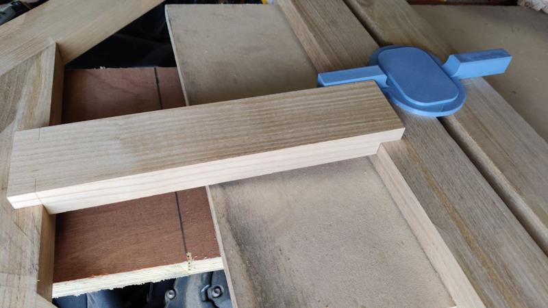
There was then a stage of rinse and repeat as I brought the other three central pieces to the same stage:
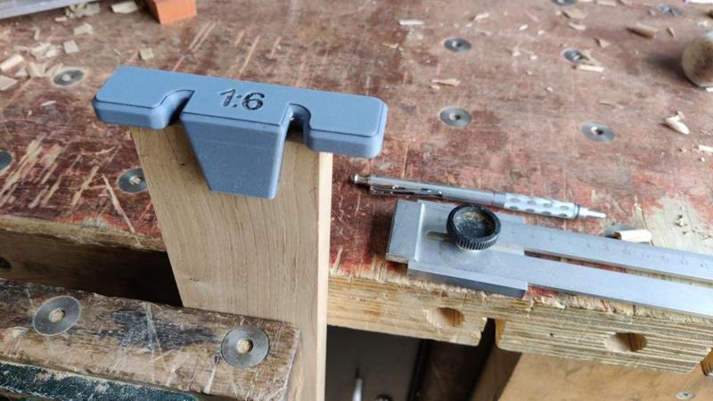
The tails were then marked, using my edge distance gauge thing to mark 12 mm in from each edge and then a simple 3D-printed guide to mark the 1:6 angle:
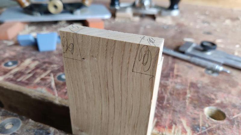
Just to err on the side of caution, I marked the waste:
The tails were then sawed to the line on the rip cut...
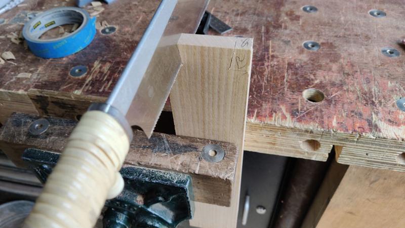
... and slightly away from the line on the cross-cut, leaving a tiny little bit to pare away with a chisel.
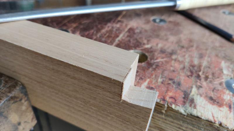
The first plank done:
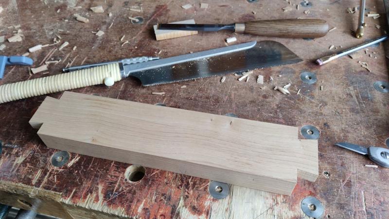
With a bit more rinse and repeat, that felt like a good time to stop for lunch, with four planks ready to have their tails transferred onto the underside of the table ready for chopping out:
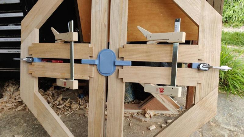
With those in place, I could clamp the planks to the table and mark the shoulder position with a knife. I could then transfer that line most of the way around each edge, just leaving a bit of a gap on the face that would end up on the underside of the table:
A steel rule was used to mark a position about 20 mm out from those knife lines (for the end of the dovetail) and that was also knifed all the way around (on both ends of the board):
On the first board, I created a knife wall with a chisel...
... and then sawed in the knife wall directly, figuring that the position didn't need to be super accurate (as I'd be cutting the slot to match) so I might as well saw straight to the line::
However, that left a little bit that needed to be pared away (as the saw hadn't cut **quite** to the knife line) so on the subsequent ones I just sawed to (roughly) the knife line and then gave each board a few passes on the shooting board to square up the ends. Only a relatively small proportion of the end needs to be square, but the shooting board seemed to me to be the quickest way to give a nice reference surface.
I set up a marking gauge for the depth of the lap joint and, while I was at it, I also set up one of my router planes to be cutting in that marking gauge line when referenced off the face side.
To cut the lap, I used a cross-cut Dozuki to cut a millimetre or so from the line...
... and then a rip Dozuki to cut a millimetre or so away from the other line:
I've heard a few people say that this sort of joint should be done by sawing directly to the line, but that is a lot more risky and, more significantly in my opinion, would remove the step that involves using my two favourite tools, a chisel and a router plane (or in this case two router planes):
The chisel was used to trim the shoulder lines; the router planes were used for the cheeks. I had set the Stanley one up to cut exactly on the marking gauge line. The Veritas one (which has a much better depth stop) had its depth stop set such that it would cut very slightly above the gauge line, so I could use the Veritas one to rough out the cheek, taking three or four passes to get down to the depth stop. The Stanley one then did the final pass to get it perfect.
I could have just set the depth stop on the Veritas one for the gauge line, but using the second router plane just means I didn't have to worry about any possible slipping of the depth stop.
With that done, I could do a quick test fit:
There was then a stage of rinse and repeat as I brought the other three central pieces to the same stage:
The tails were then marked, using my edge distance gauge thing to mark 12 mm in from each edge and then a simple 3D-printed guide to mark the 1:6 angle:
Just to err on the side of caution, I marked the waste:
The tails were then sawed to the line on the rip cut...
... and slightly away from the line on the cross-cut, leaving a tiny little bit to pare away with a chisel.
The first plank done:
With a bit more rinse and repeat, that felt like a good time to stop for lunch, with four planks ready to have their tails transferred onto the underside of the table ready for chopping out:
Dr.Al
Old Oak
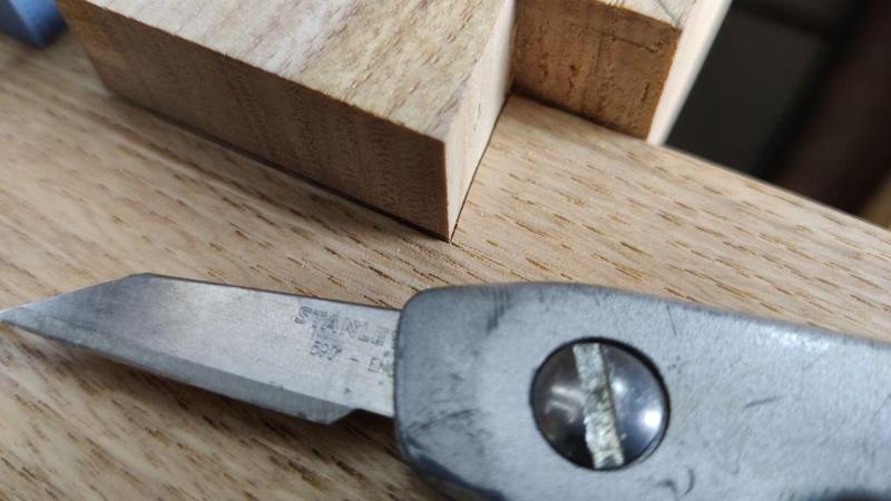
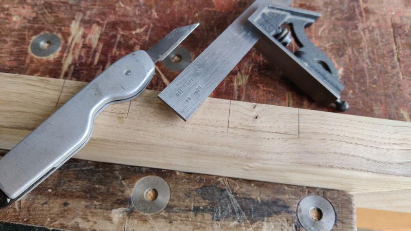
After a short digression to upgrade our cat flap from one that needs a magnet on a collar to one that reads the microchip in the neck (as a result of another cat in the neighbourhood presumably also having a magnetic collar and hence getting into our house), I started the afternoon by marking out all the pockets with a knife:
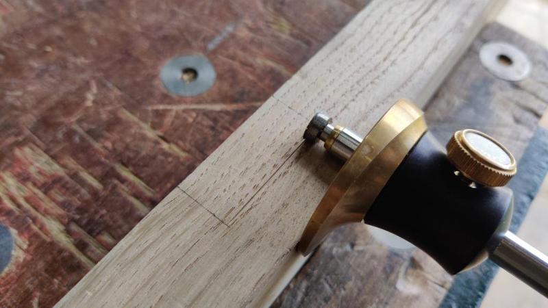
I then used the same marking gauge as before (on the same setting) to mark the depth of the pockets, marking from the face side:
I then knifed down the sides of the pockets for good measure.
Cutting out the pockets was similar to preparing dovetails in drawer fronts: I started by sawing to the line with the Dozuki:
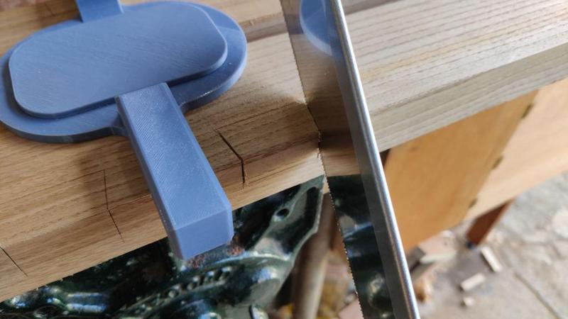
For sawing, I had the table clamped to the bench like this:
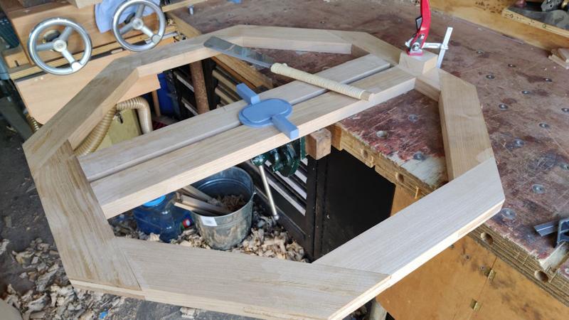
That didn't make for the most ergonomic sawing position: I had my arm going down through one opening in the table so it could grip the saw from underneath the table as the saw protruded through the other opening:
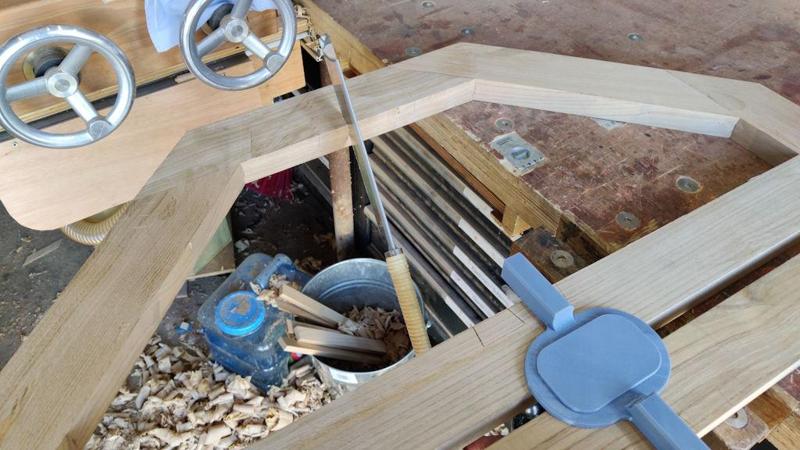
Nevertheless, it was quite easy to see what I was doing while I sawed, so it didn't take long. The remains then got chopped out:
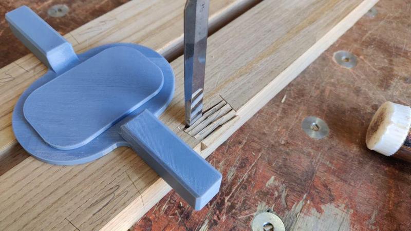
Finishing to depth was done with a router plane on some of them and just with the chisel on others. Part of the reason was that I hadn't bothered to tap out the central location 3D-printed thing and it would have got in the way of the router plane, but part of it was also that I thought the chisel practice would do me good. The first one chopped out...
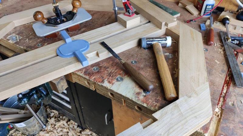
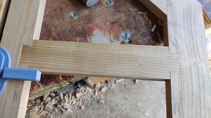
... and the slat fitted:
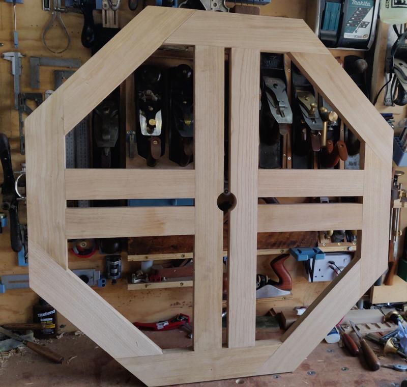
After doing the first one, I sawed and chopped all the others in one go before fitting them all. I took a photo of them all tapped (but not glued) home but it came out so blurry you couldn't see anything. I'll take another one later. In the meantime, this is the top side of the table:
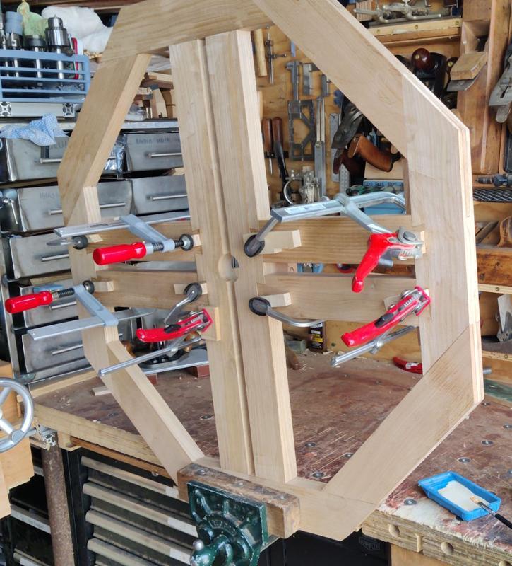
All was looking good to me, so I tapped it back apart, slathered on some glue and then tapped it back together. It holds together pretty well on its own, but I figured clamps couldn't hurt:
I then used the same marking gauge as before (on the same setting) to mark the depth of the pockets, marking from the face side:
I then knifed down the sides of the pockets for good measure.
Cutting out the pockets was similar to preparing dovetails in drawer fronts: I started by sawing to the line with the Dozuki:
For sawing, I had the table clamped to the bench like this:
That didn't make for the most ergonomic sawing position: I had my arm going down through one opening in the table so it could grip the saw from underneath the table as the saw protruded through the other opening:
Nevertheless, it was quite easy to see what I was doing while I sawed, so it didn't take long. The remains then got chopped out:
Finishing to depth was done with a router plane on some of them and just with the chisel on others. Part of the reason was that I hadn't bothered to tap out the central location 3D-printed thing and it would have got in the way of the router plane, but part of it was also that I thought the chisel practice would do me good. The first one chopped out...
... and the slat fitted:
After doing the first one, I sawed and chopped all the others in one go before fitting them all. I took a photo of them all tapped (but not glued) home but it came out so blurry you couldn't see anything. I'll take another one later. In the meantime, this is the top side of the table:
All was looking good to me, so I tapped it back apart, slathered on some glue and then tapped it back together. It holds together pretty well on its own, but I figured clamps couldn't hurt:
Dr.Al
Old Oak
Thanks AndyThat's looking lovely!
This is probably going to fly a bit like a lead balloon, but I'm trying to decide if you could have found more complicated technical solutions than the ones you've selected for making a table top. For me, it would have been stopped M&T's everywhere thus limiting as much as possible the amount of exposed joinery meeting points into which water can easily penetrate. For a garden table exposed to the elements I don't get the point of those bridle joints in the outer octagonal frame, and the dovetails at either end of the slats add little or nothing to strength and are actually something of a weakness in the vertical plane.
I can just about understand the desire to take on the technical challenge of manufacture for the fun of it, but the joinery selection does seem at least a little eccentric to me. Slainte.
I can just about understand the desire to take on the technical challenge of manufacture for the fun of it, but the joinery selection does seem at least a little eccentric to me. Slainte.
My guess is the choice of joinery is what happens when an engineering brain attacks woodwork.
fascinating to follow nonetheless.
fascinating to follow nonetheless.
Dr.Al
Old Oak
This is probably going to fly a bit like a lead balloon, but I'm trying to decide if you could have found more complicated technical solutions than the ones you've selected for making a table top. For me, it would have been stopped M&T's everywhere thus limiting as much as possible the amount of exposed joinery meeting points into which water can easily penetrate. For a garden table exposed to the elements I don't get the point of those bridle joints in the outer octagonal frame, and the dovetails at either end of the slats add little or nothing to strength and are actually something of a weakness in the vertical plane.
I can just about understand the desire to take on the technical challenge of manufacture for the fun of it, but the joinery selection does seem at least a little eccentric to me. Slainte.
Thanks for the comments @Richard; it doesn't "fly like a lead balloon": I genuinely appreciate the comment. I'm always happy to receive feedback (as long as it's based on a good justification like the one you've provided and not just "that's not the way I was taught" or other such dogma).
It is, of course, too late to change anything, but it's an interesting point nonetheless. I'd originally planned to do half-lap joints for the outside corners (which probably wouldn't have been any better per your comment). I switched to bridle joints following a suggestion from @MikeG (one which I've nearly forgiven him for now
). My original plan had been to use M&Ts for the cross-bars and slats, but what put me off that course was how much of a pig it would have been to assemble. Even ignoring the fact that it would mean assembling everything in one go (rather than being able to add the slats later as I am currently doing), the angled edges might have made it quite awkward to get everything together with mortices pointing in lots of different directions. If the angled edges were morticed together (something I hadn't considered to be honest) then assembly could be even more difficult. Preparing the joints would have been much, much easier and quicker though!I'm not for a second disagreeing with you about what's the right type of joinery (I genuinely have no idea as this is the first bit of furniture I've ever really designed - my only other bit of furniture was a very simple side table that was made in much the same was any other side table on the planet).
I guess only time will tell how much of an issue it is. I'd be surprised if there's a strength issue: the dovetail joints are very tight so would probably stay together without glue. It's not like the crosswords and drinks that we'll put on the table are going to be applying a lot of downward force. As for water ingress, that's definitely more of a concern, especially since I didn't do an amazing job of getting gap-free bridle joints. The dovetails should be okay-ish I think - any water ingress will be similar to what would be seen by a M&T joint (down the shoulder line) and there's more wood volume where the water would land on than there would be with a tenon. I'm quite tempted to find some sort of gap-filling but water-resistant product (perhaps just waterproof wood filler or TB3 mixed with sawdust) to fill in as many gaps as I can find in the hope of reducing the opportunities for water ingress.
My guess is the choice of joinery is what happens when an engineering brain attacks woodwork.
fascinating to follow nonetheless.
I think it's more a case of what happens when someone who doesn't know any better but who enjoys trying new things (I'd never cut a bridle joint or that sort of dovetail before this project) tries to come up with a design from scratch. I'm an electronics engineer, so I'm not sure my engineering brain helps much with woodwork!
duke
Old Oak
I do like your alignment tool! Looking good.After a short digression to upgrade our cat flap from one that needs a magnet on a collar to one that reads the microchip in the neck (as a result of another cat in the neighbourhood presumably also having a magnetic collar and hence getting into our house), I started the afternoon by marking out all the pockets with a knife:
I then used the same marking gauge as before (on the same setting) to mark the depth of the pockets, marking from the face side:
I then knifed down the sides of the pockets for good measure.
Cutting out the pockets was similar to preparing dovetails in drawer fronts: I started by sawing to the line with the Dozuki:
For sawing, I had the table clamped to the bench like this:
That didn't make for the most ergonomic sawing position: I had my arm going down through one opening in the table so it could grip the saw from underneath the table as the saw protruded through the other opening:
Nevertheless, it was quite easy to see what I was doing while I sawed, so it didn't take long. The remains then got chopped out:
Finishing to depth was done with a router plane on some of them and just with the chisel on others. Part of the reason was that I hadn't bothered to tap out the central location 3D-printed thing and it would have got in the way of the router plane, but part of it was also that I thought the chisel practice would do me good. The first one chopped out...
... and the slat fitted:
After doing the first one, I sawed and chopped all the others in one go before fitting them all. I took a photo of them all tapped (but not glued) home but it came out so blurry you couldn't see anything. I'll take another one later. In the meantime, this is the top side of the table:
All was looking good to me, so I tapped it back apart, slathered on some glue and then tapped it back together. It holds together pretty well on its own, but I figured clamps couldn't hurt:
Dr.Al
Old Oak
Thanks ScottI do like your alignment tool! Looking good.
To be honest, Dr All, I didn't clock your project until perhaps three or four weeks back. It seems this thread has been around for about a year and I didn't see or get involved in your design development discussions. Having only really only started noticing what you were doing recently was when I started questioning the chosen technical solutions. In truth, I've only really lightly skimmed earlier parts of the thread so I'm only now aware of the to-ing and fro-ing that went on earlier.Thanks for the comments @Richard; it doesn't "fly like a lead balloon": I genuinely appreciate the comment. I'm always happy to receive feedback (as long as it's based on a good justification like the one you've provided and not just "that's not the way I was taught" or other such dogma).
I think it's more a case of what happens when someone who doesn't know any better but who enjoys trying new things (I'd never cut a bridle joint or that sort of dovetail before this project) tries to come up with a design from scratch. I'm an electronics engineer, so I'm not sure my engineering brain helps much with woodwork!
Still, if I'd been involved in that earlier part of the thread I would have strongly suggested considering the all M&T solution. The assembly is easier than you seem to have imagined. I can see how it can be done in as little as three stages, although five stages would also be an option, and in both cases a gluing up jig or two would probably be useful. Slainte.
duke
Old Oak
Al, how did you figure out my first name? Not that I mind. Last evening was trying to figure out how to put my full name below my location but with limited computer savvy failed. So If a mod could do it great.Thanks Scott
Thanks from Scott Dukeshire.
Men and women in the Dukeshire family have always carried the nickname duke.
Dr.Al
Old Oak
Al, how did you figure out my first name?
Ah, sorry, I tend to think in names rather than usernames. I figured it out because you sent me a message a while ago via my website contact form and ever since I've just naturally thought of you as Scott.
To set your name, click on your name in the top-right of the screen and click "Account Details":Not that I mind. Last evening was trying to figure out how to put my full name below my location but with limited computer savvy failed. So If a mod could do it great.

Part-way down the resulting page you'll see a box where you can type it in:

Dr.Al
Old Oak
A comment from someone on the MIG-welding forum made me go back and re-visit the design plan. One of my earlier layout ideas had a simple cross in the middle with all the remaining slats at 45°. At the time I wasn't sold on the look of it, but after getting that comment I thought it was worth another look now that the central cross is a bit more interesting with the two bars in each axis.
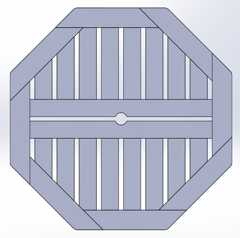
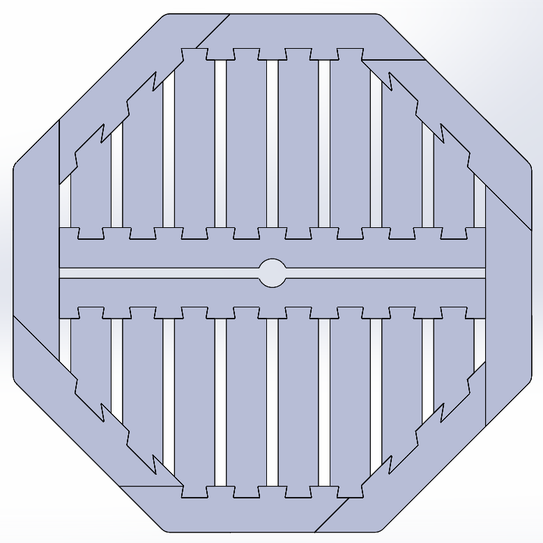
First of all though, I thought I'd draw out the existing design including all the dovetails all the way around. I've offset the angled ones slightly (following a comment earlier in this thread from @spb) as it does indeed seem to make it look better if they're not perfectly centred. Here's the current design top and bottom view:
The alternative layout is a bit more complex to make (especially to make everything look balanced) but I think I quite like the style of it (even if it does result in some rather weird shapes in the dovetail cut-outs). Top and bottom views:
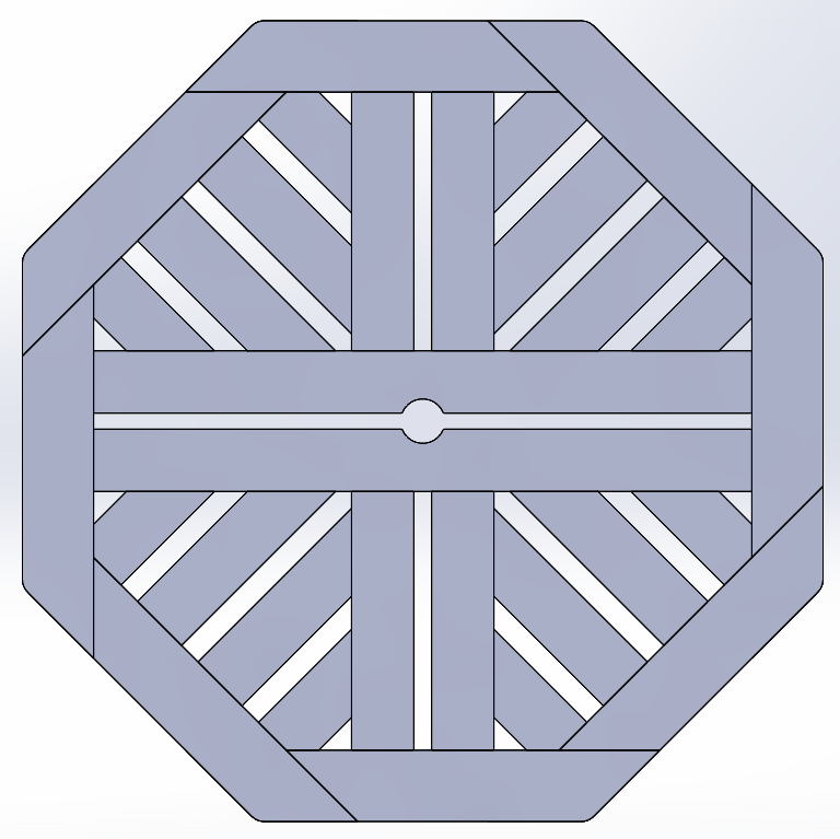
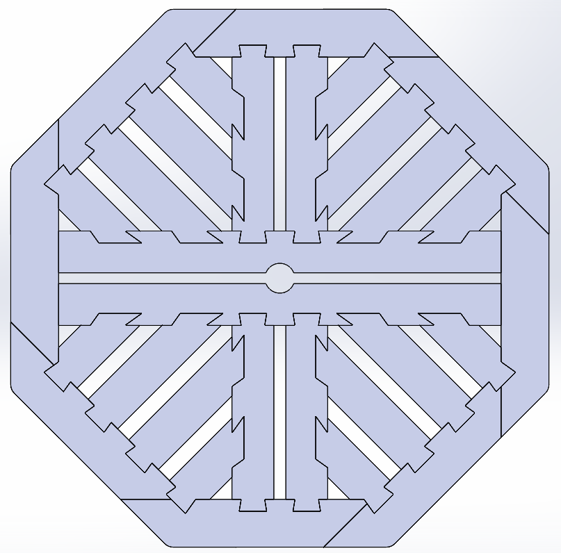
The gaps between the angled slats would be slightly bigger (26 mm) than the gaps between the cross bars, but that's probably not the end of the world. The gaps between the cross-bars shown as vertical in those images (20 mm) are already slightly bigger than the one between the horizontal cross-bar (18 mm), so another gap thickness in a different position probably doesn't matter too much (I hope).
I'd welcome any thoughts, although of course the design authority (my other half) will have the final say!
First of all though, I thought I'd draw out the existing design including all the dovetails all the way around. I've offset the angled ones slightly (following a comment earlier in this thread from @spb) as it does indeed seem to make it look better if they're not perfectly centred. Here's the current design top and bottom view:
The alternative layout is a bit more complex to make (especially to make everything look balanced) but I think I quite like the style of it (even if it does result in some rather weird shapes in the dovetail cut-outs). Top and bottom views:
The gaps between the angled slats would be slightly bigger (26 mm) than the gaps between the cross bars, but that's probably not the end of the world. The gaps between the cross-bars shown as vertical in those images (20 mm) are already slightly bigger than the one between the horizontal cross-bar (18 mm), so another gap thickness in a different position probably doesn't matter too much (I hope).
I'd welcome any thoughts, although of course the design authority (my other half) will have the final say!
duke
Old Oak
No need for the apology all is good . Thanks.Ah, sorry, I tend to think in names rather than usernames. I figured it out because you sent me a message a while ago via my website contact form and ever since I've just naturally thought of you as Scott.
To set your name, click on your name in the top-right of the screen and click "Account Details":
View attachment 33325
Part-way down the resulting page you'll see a box where you can type it in:
View attachment 33326
The alternative design could look a little bit flag-like to some people. (Almost reminiscent of those LED tail lights you see on modern Minis.)
But it's too late to change now, isn't it? This is just a theoretical digression?
But it's too late to change now, isn't it? This is just a theoretical digression?
Dr.Al
Old Oak
The alternative design could look a little bit flag-like to some people. (Almost reminiscent of those LED tail lights you see on modern Minis.)
But it's too late to change now, isn't it? This is just a theoretical digression?
Not too late to change, no. This is what it looks like at the moment:
I haven't started cutting the pieces for the corners, so they could either be parallel to the two slats I fitted yesterday or they could be at 45°.

Mike G
Petrified Pine
I defintitely prefer the top design. The doubled central piece is an update I had missed, too, somehow. I don't know how practical such wide gaps are, though. I can imagine knives dropping through quite regularly for people sitting facing the ends of slats.
Dr.Al
Old Oak
I definitely prefer the top design.
Thanks Mike. I think I'm leaning that way too (but as I said it'll mostly be up to Carolyn!)
The doubled central piece is an update I had missed, too, somehow
That change was made in response to a comment on here from @Mike Jordan . He noted that if the single central cross-bar expands width-ways, then it pushes the slats out and could damage the rim. It didn't feel likely to be that much of a problem to me given the narrowness of the central bar, but he'd seen it as a real problem on a table he'd made, so I thought it best to do something about it. With the doubled cross-bar, it will hopefully expand into the gap rather than push the slats out.
I don't know how practical such wide gaps are, though. I can imagine knives dropping through quite regularly for people sitting facing the ends of slats.
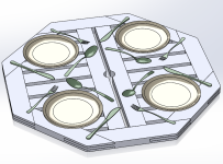
It's a good point and one I'd not considered. However, having thought about it now I'm not too concerned about it: the table isn't that big and there will never be more than four people sitting around it. I can't see any real reason why anyone would ever have to sit facing the ends of the slats. A hastily knocked-up and roughly-to-scale CAD model:
Dr.Al
Old Oak
I haven't had much time in the workshop over the past couple of weeks, but this afternoon was clear so I thought it would be good to make a bit of progress on the table top. I've decided to go with the original-ish design (with parallel side slats rather than the angled ones in the corner pockets). Therefore, the next slats to go in are the ones either side of the existing ones. These are relatively simple as the dovetails are still fairly conventional.
I started by marking the shoulder lines as before, but just using the simple spacers to keep everything evenly spaced and parallel:
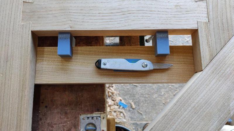
Unfortunately I had a moment of stupidity and did this on the underside face (with the table top upside down) rather than the top face (with the table the right way up). That meant that I'd scribed a line across the bit of dovetail that would remain after cutting out:
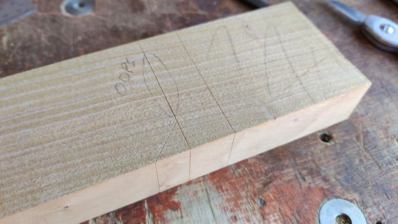
Not the end of the world though. I could have just grabbed another bit of wood and had another go, but I figured that it'll probably get planed down later and even if it doesn't, it's on the underside of the table so doesn't really matter.
Marking the depth was done in the same way as before:
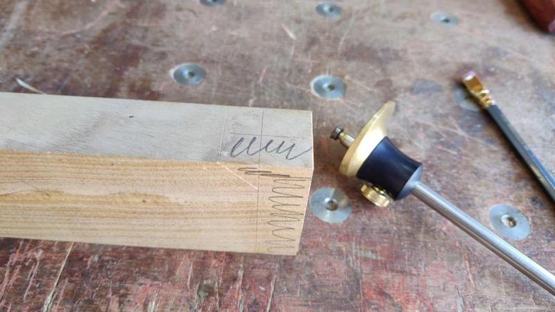
Then I roughly sawed the ends, initially ignoring the little corner bit:
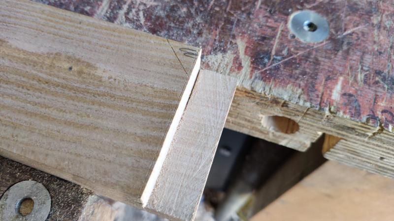
The corner bit then got sawn off as well:
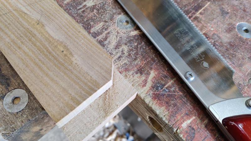
Then it was just more chisel & router plane time to shape the plank:
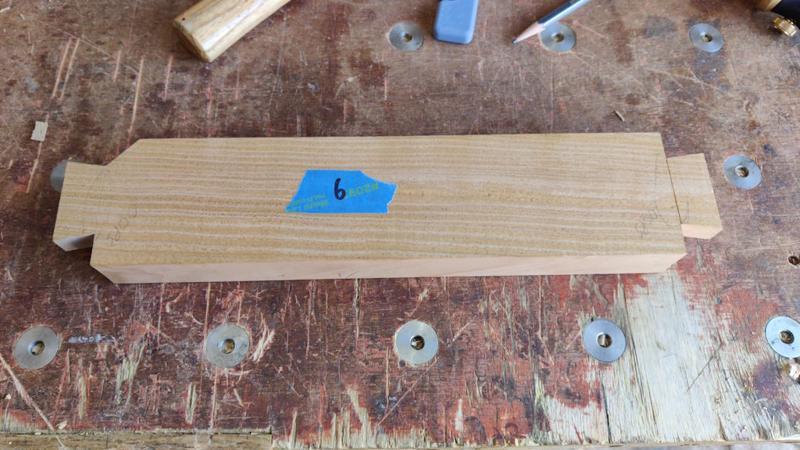
The little spacers were used again to hold it in the right place to mark the pocket locations:
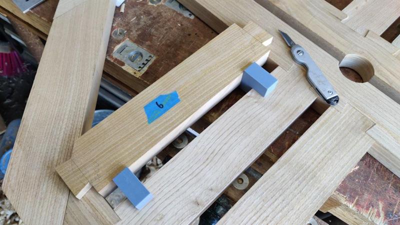
The process was then much the same as before to chisel out the waste and fit the first plank:
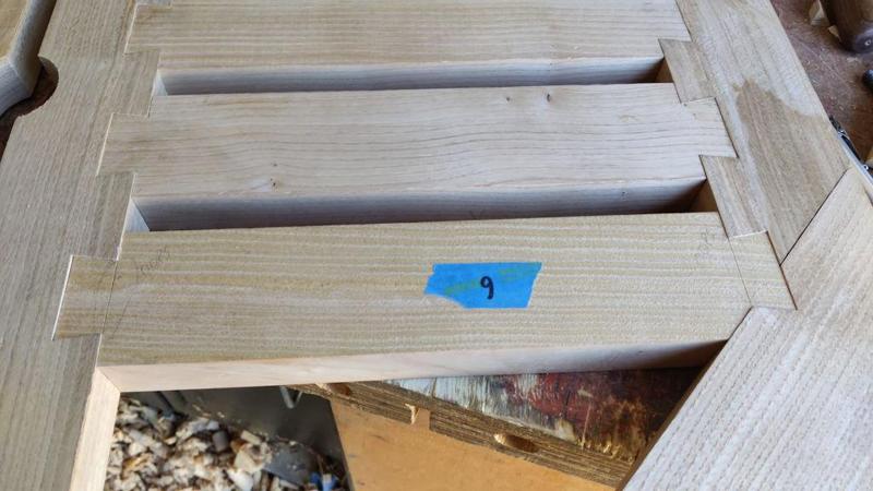
For the other three similar ones, the process was basically the same, except that I marked the shape on the correct side for these ones and also that I did all the various operations three times (once on each plank) before moving onto the next plank. That made for quite an efficient process and I fairly quickly got to the point of having all four fitted:
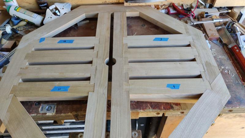
I haven't glued them in yet as I think it'll make sawing the sides of the remaining dovetail pockets a lot easier if I remove those planks to give my arm a bit more space to work in. This is what the table looks like now:
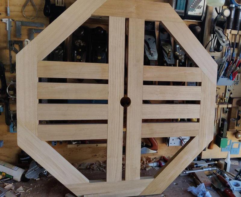
Next will be to work on the planks with the angled ends, for which I'm currently 3D-printing a little marking gauge to make things nice and easy to layout consistently.
I started by marking the shoulder lines as before, but just using the simple spacers to keep everything evenly spaced and parallel:
Unfortunately I had a moment of stupidity and did this on the underside face (with the table top upside down) rather than the top face (with the table the right way up). That meant that I'd scribed a line across the bit of dovetail that would remain after cutting out:
Not the end of the world though. I could have just grabbed another bit of wood and had another go, but I figured that it'll probably get planed down later and even if it doesn't, it's on the underside of the table so doesn't really matter.
Marking the depth was done in the same way as before:
Then I roughly sawed the ends, initially ignoring the little corner bit:
The corner bit then got sawn off as well:
Then it was just more chisel & router plane time to shape the plank:
The little spacers were used again to hold it in the right place to mark the pocket locations:
The process was then much the same as before to chisel out the waste and fit the first plank:
For the other three similar ones, the process was basically the same, except that I marked the shape on the correct side for these ones and also that I did all the various operations three times (once on each plank) before moving onto the next plank. That made for quite an efficient process and I fairly quickly got to the point of having all four fitted:
I haven't glued them in yet as I think it'll make sawing the sides of the remaining dovetail pockets a lot easier if I remove those planks to give my arm a bit more space to work in. This is what the table looks like now:
Next will be to work on the planks with the angled ends, for which I'm currently 3D-printing a little marking gauge to make things nice and easy to layout consistently.
Cabinetman
Sequoia
- Joined
- Oct 11, 2020
- Messages
- 5,528
- Reaction score
- 1,231
- Location
- Lincolnshire Wolds + Massachusetts
- Name
- Ian
It looks like very neat work Al, the only thing I would have done differently would have been to juggle the width of slat and gaps to make the edge of the slat hit the outer frame in the corner. But that’s just me being awkward and probably altering the spacing would have kyboshed it somewhere else no doubt.
Ian
Ian
NickM
Old Oak
That's looking really good.
Dr.Al
Old Oak
It looks like very neat work Al, the only thing I would have done differently would have been to juggle the width of slat and gaps to make the edge of the slat hit the outer frame in the corner. But that’s just me being awkward and probably altering the spacing would have kyboshed it somewhere else no doubt.
Ian
That's an interesting point and it may well have looked better that way. To be honest, the layout was partly deliberate (although it was mostly a consequence of the size the planks came out). There are some small (but noticeable by me at least) gaps at the "root" (bottom, inside?) of some of the bridle joints. Four of those roots rather conveniently get hidden by the slats! If you look back at the "flag" style design with the angled corner pieces, you'll see that all of the bridle joint roots would have been covered.
That's looking really good.
Thanks Nick.
duke
Old Oak
Al, all your joinery is making my head spin and as Nick said it is looking really good.