• Hi all and welcome to TheWoodHaven2 brought into the 21st Century, kicking and screaming! We all have Alasdair to thank for the vast bulk of the heavy lifting to get us here, no more so than me because he's taken away a huge burden of responsibility from my shoulders and brought us to this new shiny home, with all your previous content (hopefully) still intact! Please peruse and feed back. There is still plenty to do, like changing the colour scheme, adding the banner graphic, tweaking the odd setting here and there so I have added a new thread in the 'Technical Issues, Bugs and Feature Requests' forum for you to add any issues you find, any missing settings or just anything you'd like to see added/removed from the feature set that Xenforo offers. We will get to everything over the coming weeks so please be patient, but add anything at all to the thread I mention above and we promise to get to them over the next few days/weeks/months. In the meantime, please enjoy!

Dr Al's Latest Folly

That's a shame, Al. The only option I can think of which doesn't involve starting from scratch would be to bore out even more material, press in a new bit of round steel with a tight interference fit, and then start your boring again. It's probably easier just to start from scratch.
 
That's a shame, Al. The only option I can think of which doesn't involve starting from scratch would be to bore out even more material, press in a new bit of round steel with a tight interference fit, and then start your boring again. It's probably easier just to start from scratch.

That would definitely be an option; in theory I could even do it with one of the off-the-shelf sleeves (although I've already bored the end out bigger than the outer diameter of that one). However I think I'll just end up forever looking at it with regret so I'm going to be much happier if I remake it (more carefully!).
 
After getting back from the "joys" of Christmas supermarket shopping, I finished off the spindle by cross-drilling the hole for the tommy bar:

2025-12-23-10-cross-drilling-spindle_800.jpg


Ignoring the minor inconvenience of making the spindle again from scratch once the 50 mm bar has arrived, that's the spindle done.

Rather than dwell on my mistake, I thought I'd get on with the next job: a new lid for the headstock. The current lid is a bit of relatively thin plate with a hole in it (for the tommy bar) and a sliding cover for the hole. The cover can easily get knocked (or vibrated) away from covering the hole, which isn't ideal. When I opened the lid as part of the disassembly of the lathe, the headstock had rather a lot of sawdust inside. I'd like to improve that.

When I made the original lid, I took advantage of the relative flexibility of the thin steel sheet and didn't bother to machine the top surface of the headstock. For the new lid I'd like a flat reference so the first job was to stick the headstock in the milling vice and run an end mill around the top surface:

2025-12-23-11-milling-top-of-headstock_800.jpg


Next up was the lid, which is going to be made from a big lump of aluminium I found in the skip. The aluminium block was much too large so the first job was to cut a bit under half of it off in the bandsaw. The cut-off bit then got mounted in the mill vice and I used my big flywheel fly cutter to clean up all the faces and bring it to the target dimension. In progress shot:

2025-12-23-12-flycutting-aluminium-block_800.jpg


The fly cutter leaves a lovely finish:

2025-12-23-13-lovely-finish_800.jpg


After squaring up all six faces:

2025-12-23-14-flycut-all-round_800.jpg


I then used a 16 mm end mill to cut a profile into the underside of the aluminium block:

2025-12-23-15-milled-to-shape_800.jpg


The tallest bit drops down between the two bearing retainers and provides enough material for some screws to come in from front and back (rather than above) so I can use bigger screws (compared to the M3 ones I used on the previous lid). The shallower bit sits fully inside the lid against the edges of the headstock.

Before finishing for the day, I did a test fit, dropping the headstock (with bearing retainers fitted) onto the lid to check there were no clashes:

2025-12-23-16-test-fit-with-bearing-retainers-fitted_800.jpg
 
I'm always impressed by your projects Al, it took me 2 days just to surface grind and fit a strip to align the vice on my new mill. May I ask what was your job.
 
I'm always impressed by your projects Al

Thanks Wallace; the feeling's mutual.

May I ask what was your job.

I'm slightly intrigued by the "was" in that sentence: I must look older than I am! (Yes, I know you don't know what I look like :) ). I've still got 20 years or so to go before hitting retirement age.

I work as an electronics design engineer. I currently work for a metrology company designing the electronics for precision measurement devices (used for semiconductor manufacturing and high-end machining). If any of your machine tools have digital read-outs then it's a very similar concept to the scales used for that but they're typically higher precision (we do resolutions down to 1 nanometre).

I spend my days sitting in front of a computer so it's nice to have a bit of hands-on time after work, hence the enthusiasm for having a workshop.
 
Today I continued with the headstock. The first thing I did was mount the headstock in the milling vice and, with the new lid clamped in place, drilled two 6.2 mm holes in each side and also countersunk them:

2025-12-24-01-drilling-and-countersink-lid-attach-holes_800.jpg


The holes in the lid then got tapped to what I think is probably M7.2×1 mm:

2025-12-24-02-tapping-for-insert_800.jpg


That thread is the one used for an M6 V-Coil (another brand of Helicoil) insert, which was fitted in each of the four holes:

2025-12-24-03-fitting-insert_800.jpg


The main reason for using a thread insert is that it'll make the thread stronger and more resilient to having screws inserted and removed repeatedly (as the wearing surface of the thread will be steel on steel rather than steel on aluminium). One fringe benefit of doing it that way was that I could drop a screw into the drilled and countersunk pocket and check that the countersink was deep enough (I could do this because the tapping size for the coil insert is bigger than the diameter of the screw).

With that done I could fit the lid:

2025-12-24-04-lid-fitted_800.jpg


Three of the sides of the headstock then got some holes drilled. I started with the rear of the headstock, which got four M5 holes added (two with V-coil inserts and two just tapped M5 directly):

2025-12-24-05-making-holes-for-chuck-key-holder_800.jpg


You might notice that one of the lid attachment screws is missing in that photo. That's because I've only got three of them: I need to order some more!

Those holes will be for mounting the chuck key and Allen key holder. Previously, that holder had been held on with magnets but it occasionally got knocked off so I've decided to make a new one that will get screwed in place. Four screws is probably excessive but what the heck.

The front got two holes, a big one for the tommy bar (which I drilled 10 mm then finished with an end mill as I couldn't get the head up high enough to leave clearance for my 12 mm drill bit) and a smaller one to mount the cover for the big hole:

2025-12-24-08-milling-hole-for-tommy-bar_800.jpg


Finally, the left-hand side got two holes. These have different purposes to each other but share the same requirement: I want them to be roughly in the middle of the lid (top-to-bottom) and I want them to be 60 mm from the centre of the spindle axis. After measuring the distance from the centre of the bearing hole to the top of the centre of the lid, Pythagoras came to the rescue:


2025-12-24-06-pythagoras_800.jpg


That simple bit of maths gave me the locations to drill and tap an M5 hole and to drill and ream an 8 mm hole:

2025-12-24-07-reaming-hole_800.jpg


The last job to do while the head was still assembled was to run a chamfering tool around the outside, chamfering the edges of the lid at the same time as the body.

2025-12-24-09-chamfering_800.jpg


I also put a heavy chamfer on two sides of the bottom, as the raiser I added is slightly narrower than the headstock and this should soften that edge. I struggled to cut that chamfer and only after doing the second one did I realise that I hadn't tighten the collet chuck! I'm frankly amazed that I managed to do any of the other chamfers.

The final headstock job (at least until I think of any others!) was to remove the lid and cut a 4 mm wide slot in one of the edges:

2025-12-24-10-slot-milling_800.jpg


We've got family visiting from tomorrow (and I've got to cook Christmas dinner) so I'm not sure when I'll next get into the workshop. However, I have already done (but not documented) one other job on the lathe so I might find some time to write that up and post about it sometime over the next day or two.
 
Last edited:
The work described in this post actually started a few weeks ago and had the last operation completed a few days ago, but it seems to fit into the narrative a bit better here than before I'd given some context to the general upgrade work being done on the lathe.

Another of my various skip finds was this large aluminium disc, which had obviously had some milling done on it at some point:

2025-12-07-01-aluminium-plate-from-skip_800.jpg


The first thing I did on that plate was to hold it in the milling vice with the flatter of the two faces at the top. Clamping it was a bit unconventional in that I just placed a couple of parallels on the top of the vice and then clamped it in place with some F-clamps. I could then drill and tap some M5 holes spaced around the centre:

2025-12-07-02-clamped-to-vice-and-tapped_800.jpg


I'd considered making an M33×3.5 mm mount for the big plate, but I didn't have any steel of a sensible size (and the skip didn't provide me with anything appropriate). Buying a piece of steel would have cost more than this (£9.79) face plate from aliexpress, so I went with the easy option. I needed to modify it a little as I wanted countersunk holes in the rear face. I started with a countersink but it was struggling to cut (and having a relatively short shank I also managed to mash the chuck into the part):

2025-12-07-03-struggling-to-countersink-with-oops-mark_800.jpg


I switched to a spotting drill (which also has a 90° included angle) and that did a much better job:

2025-12-07-04-spotting-drill-did-better_800.jpg


I cleaned up the "oops mark" on the lathe and then screwed it to the big aluminium disc. I then mounted the face plate in the three-jaw chuck for roughing out the surface:

2025-12-07-05-mounted-in-three-jaw-for-roughing_800.jpg


Here you can see the overly long screws I used to attach the two parts together. You can also see that it only just fit on the lathe:

2025-12-07-06-just-fits-on-the-lathe_800.jpg


Here's an action shot of me cleaning up the face:

2025-12-07-07-action-shot_800.jpg


This was how I left it a few weeks ago, with a fairly clean surface but, critically, no real guarantee that the face or rim was concentric as I'd been holding it on the outside of the faceplate rather than on the chuck register:

2025-12-07-08-last-passes-with-soft-jaws-after-cleaning-up-faceplate_800.jpg


When I'd finished turning the new spindle and had it mounted in the soft jaws of the chuck (which, if you remember, were turned to size in situ and hence should be very accurately concentric with the lathe axis), I mounted the big disc on the spindle-to-be and did a final light skim cut of the outer diameter and of the face, giving me a big flat and true 250 mm disc that can easily be mounted on the wood lathe:

2025-12-23-08-skimmed-sanding-plate_800.jpg


If you haven't guessed already, this photo should explain its purpose:

2025-12-23-09-sanding-plate-finished_800.jpg


Being aluminium and not too thick, it should be relatively easy to remove the self-adhesive sanding disc when it wears out as I can just heat the back of the plate up until the glue gives way. I can then clean any left-over adhesive with acetone or similar before fitting a new disc.

I don't often sand anything but I can see it being a useful thing to have for occasional use and it'll be nice to have it as a lathe accessory rather than requiring a separate machine that I'd have to find somewhere to store.

One of the other lathe upgrades I'll do soon (with one of the other aluminium skip finds from one of the earlier photos) is to make a banjo-mounted table that can be used when sanding if desired.
 
Apoligies for aging you quite considerably, dont know where I got the impression you are retired. Not sure if it would work with aluminium but on my cast iron disc sander I polished the surface and smeared it with finishing wax. This enables the self adhesive disc to just peel off when needed. I normally keep an 80grit on it but if I wanted something finer I can swap it easily and then put the old one back on. I keep the old non stick backers to hold the discs. It used to be quite a long job putting a new disc on.
 
Apoligies for aging you quite considerably, dont know where I got the impression you are retired. Not sure if it would work with aluminium but on my cast iron disc sander I polished the surface and smeared it with finishing wax. This enables the self adhesive disc to just peel off when needed. I normally keep an 80grit on it but if I wanted something finer I can swap it easily and then put the old one back on. I keep the old non stick backers to hold the discs. It used to be quite a long job putting a new disc on.

That's a great tip; thanks. I'll see how long it lasts and how tedious it is to remove but I might well do that whenever I have to change the disc.
 
Could you not fix velcro to the aluminium plate and use 250mm hook and loop sandpaper?
Eg:-

Certainly no reason why not. If I'm honest, it wasn't something I gave much thought to. I guess the disadvantage (or advantage, depending on what you're trying to do) of velcro would be that there would be a lot more give in the sandpaper surface. If you're trying to sand something to make it flat then the softness of the backing could be a pain.

For the amount I expect to use the sanding disc, I doubt I'll change discs very often at all (especially with the use of a sandpaper cleaner). At the moment I feel like it'll just be for rough work & I can always sand by hand if smaller grits are required.

Alternatively, I can add velcro later if that seems better!
 
Apoligies for aging you quite considerably, dont know where I got the impression you are retired. Not sure if it would work with aluminium but on my cast iron disc sander I polished the surface and smeared it with finishing wax. This enables the self adhesive disc to just peel off when needed. I normally keep an 80grit on it but if I wanted something finer I can swap it easily and then put the old one back on. I keep the old non stick backers to hold the discs. It used to be quite a long job putting a new disc on.
That’s a good tip, the last time I wanted to change the paper it was quite an unpleasant job really involving solvents.
So does the disc stay put well enough?
 
Today was all about the tailstock. When I made the tailstock originally, I just used what is essentially a nut to fix it in place. It wasn't quite as low-tech as a nut: it was a cylinder of steel with a thread tapped in the bottom and a sliding tommy bar going through it. Tightening and loosening the tailstock was a case of spinning the tommy bar round clockwise or anticlockwise.

That worked okay, but the box section that forms the bed isn't perfectly even and in some places I'd find myself needing to move the nut by as much as half of a turn, at which point I had to slide the tommy bar across. Not exactly a major issue (it certainly hasn't stopped me making stuff with the lathe), but a cam-lock tailstock would be nicer.

It's not the first time I've made one (I upgraded my first metalworking mini-lathe to have a cam-lock tailstock) so I had a fairly good idea of what I was doing before I started. When I did the original cam-lock tailstock for the mini-lathe, I followed a design I found on-line but it broke after a year or so and I ended up beefing it up a bit. For this one I decided to err on the side of strong!

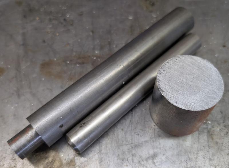
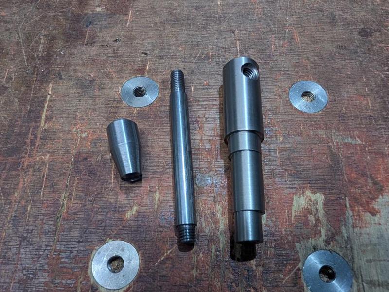
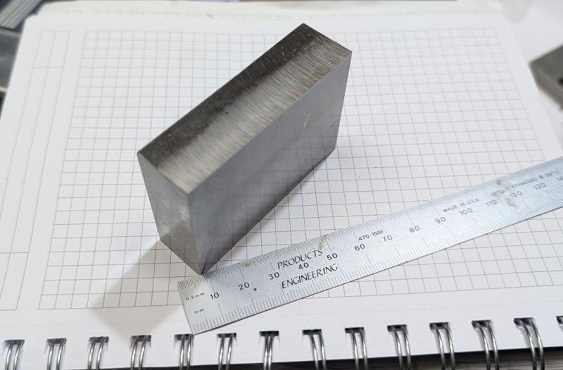
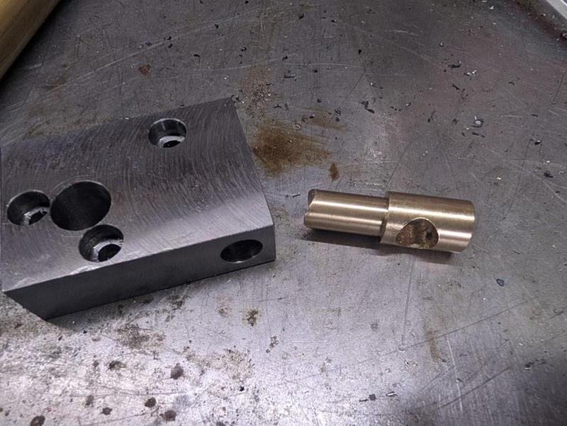
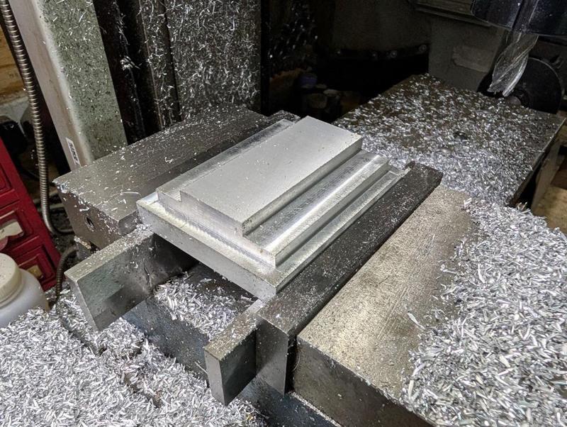
I started with these three bits of EN1A:

2025-12-27-01-three-bars-of-en1a_800.jpg


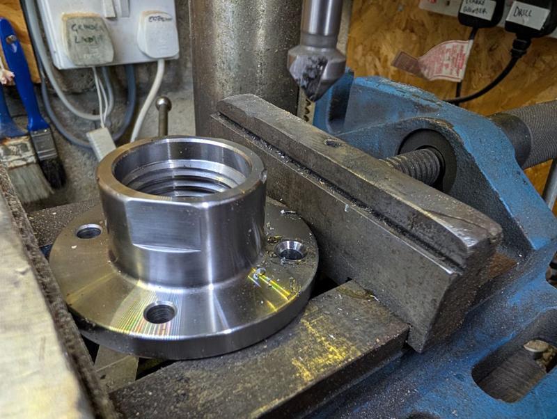
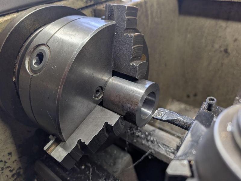
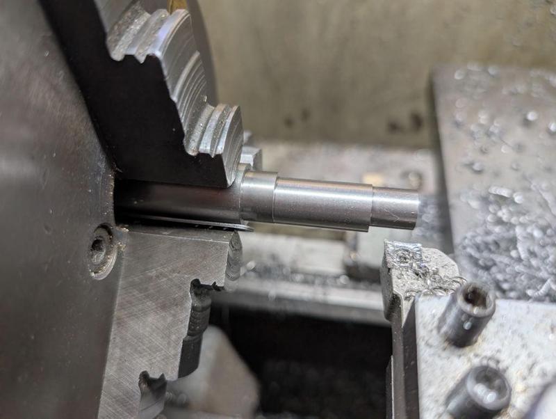
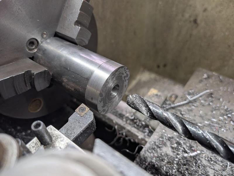
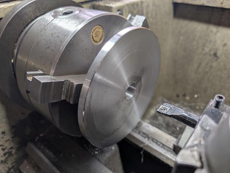
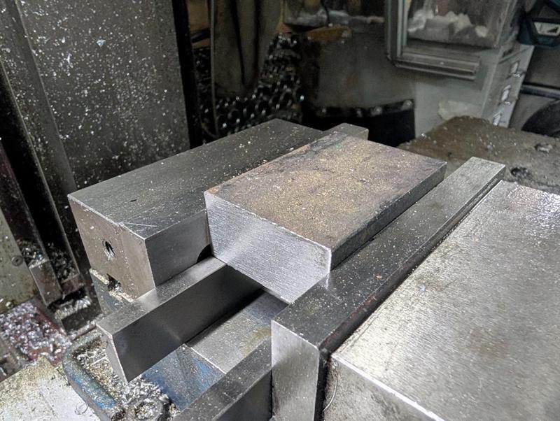
They're 20 mm, 30 mm and 50 mm diameter. I later also used a bit of 10 mm diameter EN1A as well. I started with the largest piece, which was faced off on both ends and then drilled and bored out to 30 mm to a depth of 40 mm (in the 45 mm long piece):

2025-12-27-02-boring-largest-piece_800.jpg


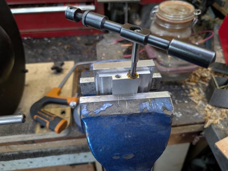
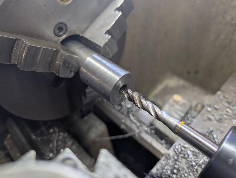
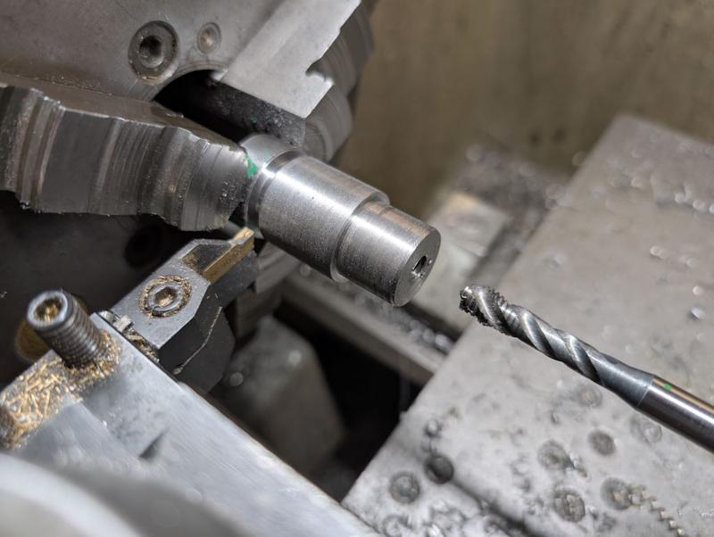
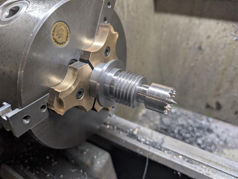
The 30 mm bar got the outside surface cleaned up and then I drilled and tapped a shallow M10 hole in the bottom:

2025-12-27-03-tapping-medium-piece_800.jpg


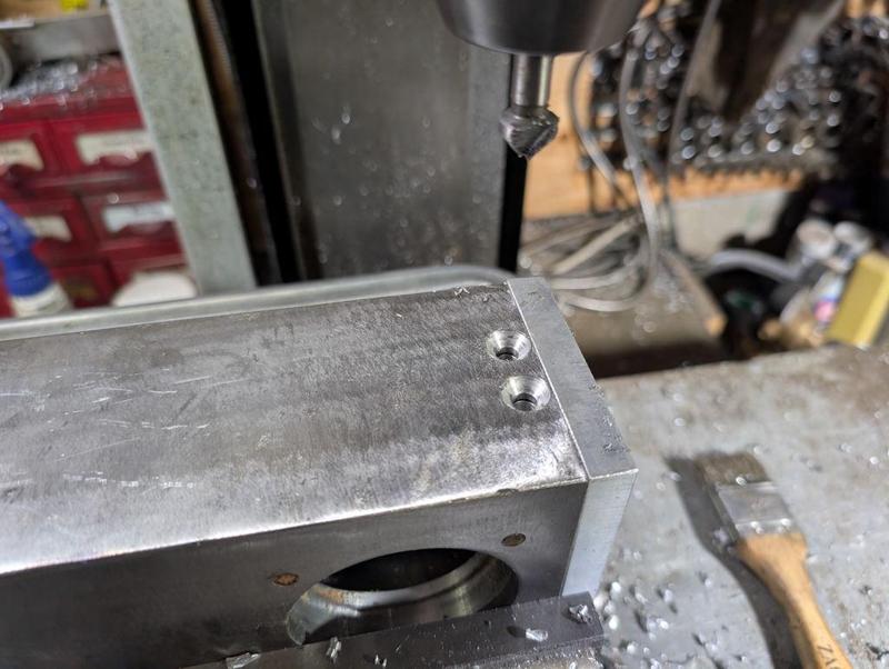
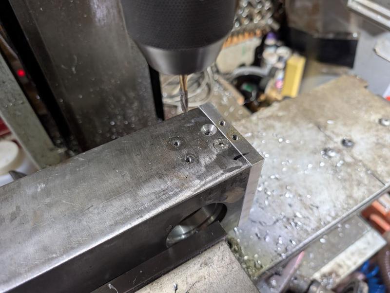
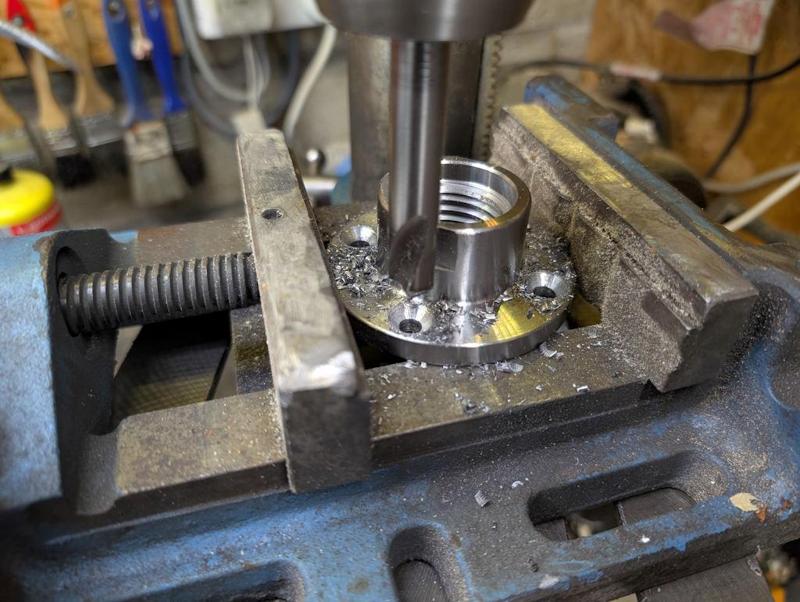
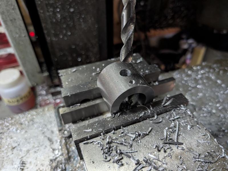
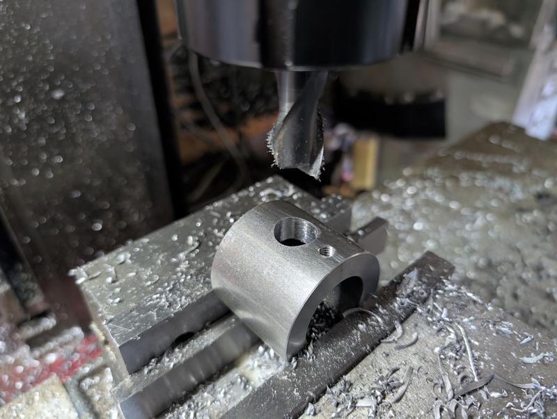
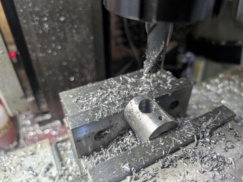
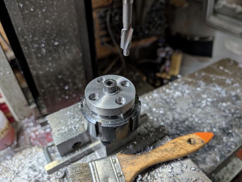
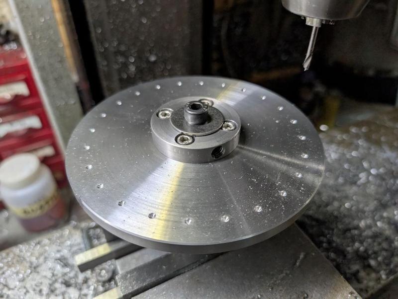
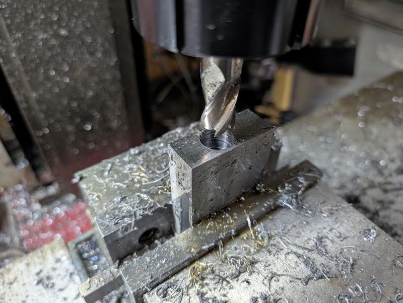
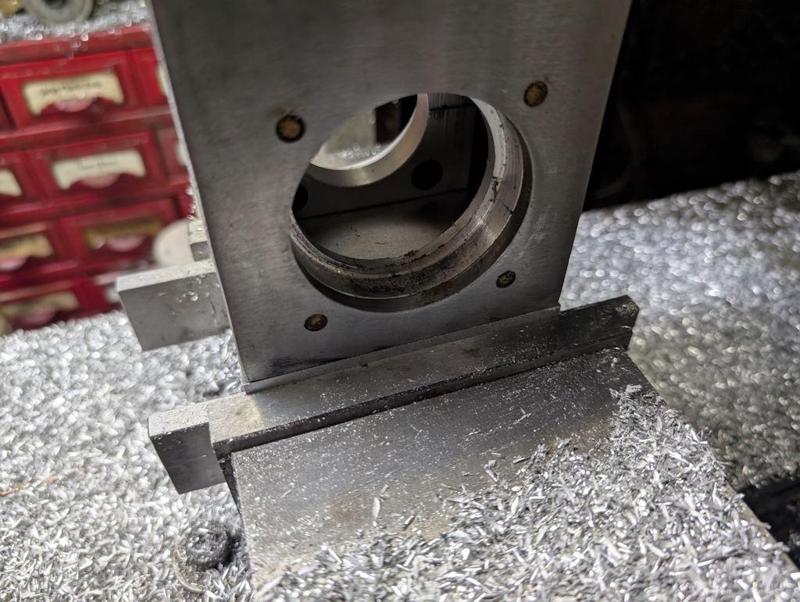
With those simple jobs done, it was over to the milling machine. I started with the bigger bit, which got drilled through 11.5 mm and also got a through 5 mm hole, which was partially tapped M6 in the more accessible side (the other side got partially tapped after it was removed from the mill vice):

2025-12-27-04-cross-drilling-big-piece_800.jpg


The M6 thread there is for a short grub screw. The only purpose of the grub screw is to block the hole and stop sawdust from getting in (hence it only being partially tapped: the grub screw will tighten into the hole without protruding into the bore or out of the outside diameter).

I only actually wanted an M6 hole for a blanking plug on one side of the part but the side I wanted it on was the underside and I wanted it to be parallel with the other hole so it seemed easiest just to drill all the way through and add a blanking grub screw on both sides.

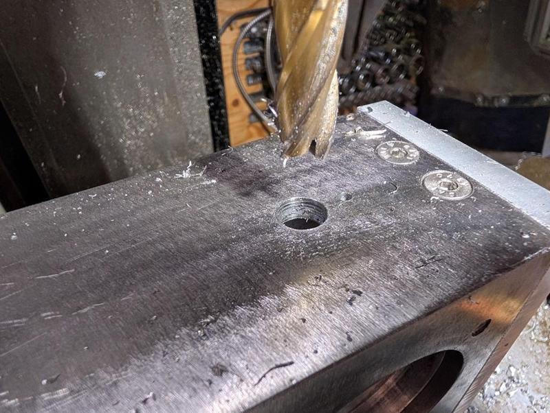
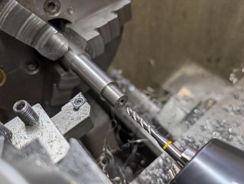
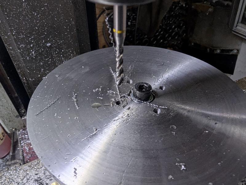
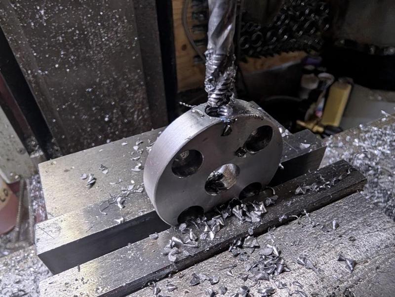
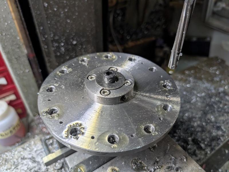
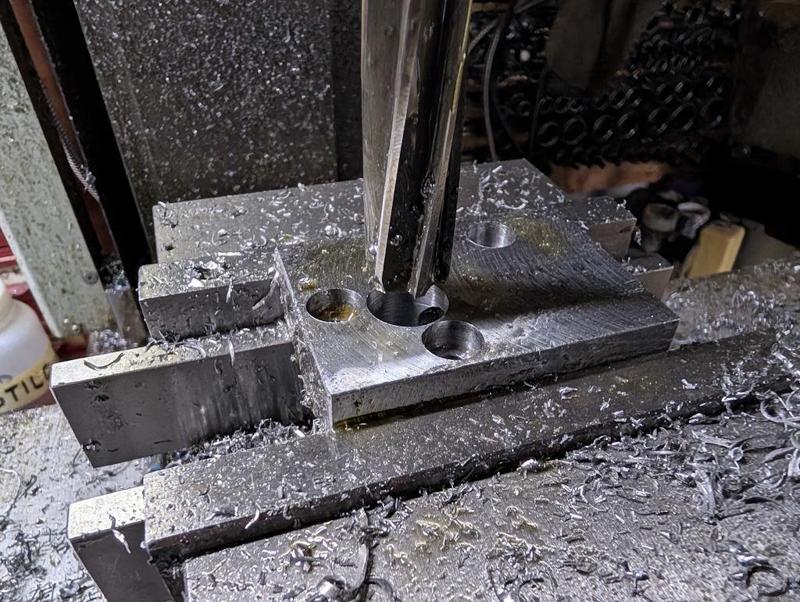
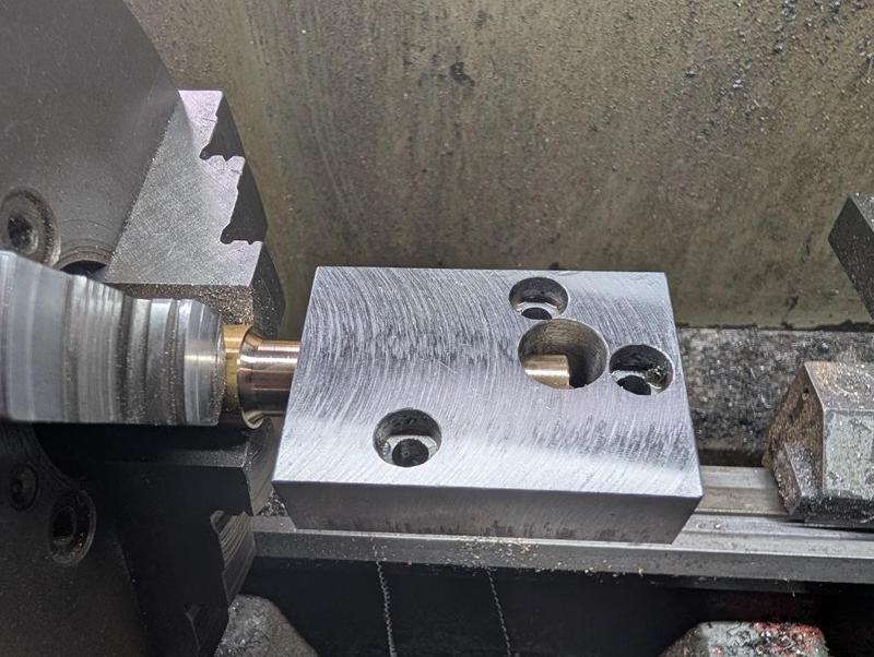
The bigger hole is to be 16 mm on the upper side and 12 mm on the lower side. For the upper side, I made the 16 mm hole with an end mill:

2025-12-27-05-16mm-end-mill_800.jpg


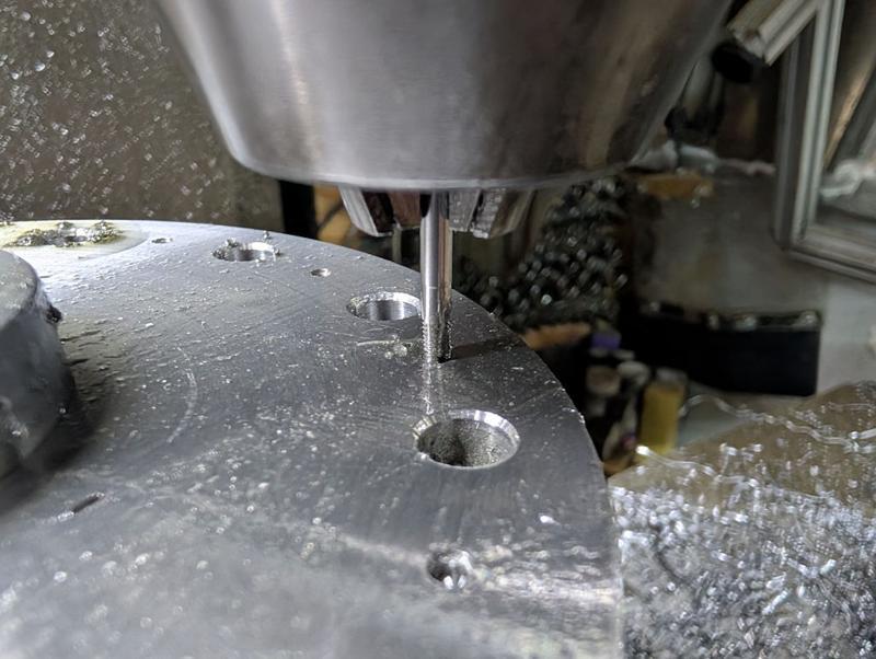
For the lower side, I converted the 11.5 mm drilled hole into a 12 mm hole with a reamer:

2025-12-27-06-12mm-reamer_800.jpg


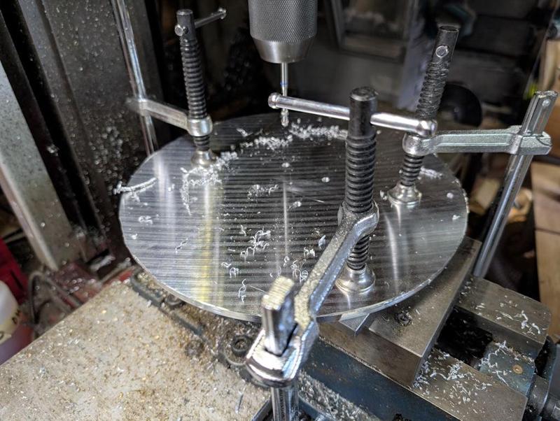
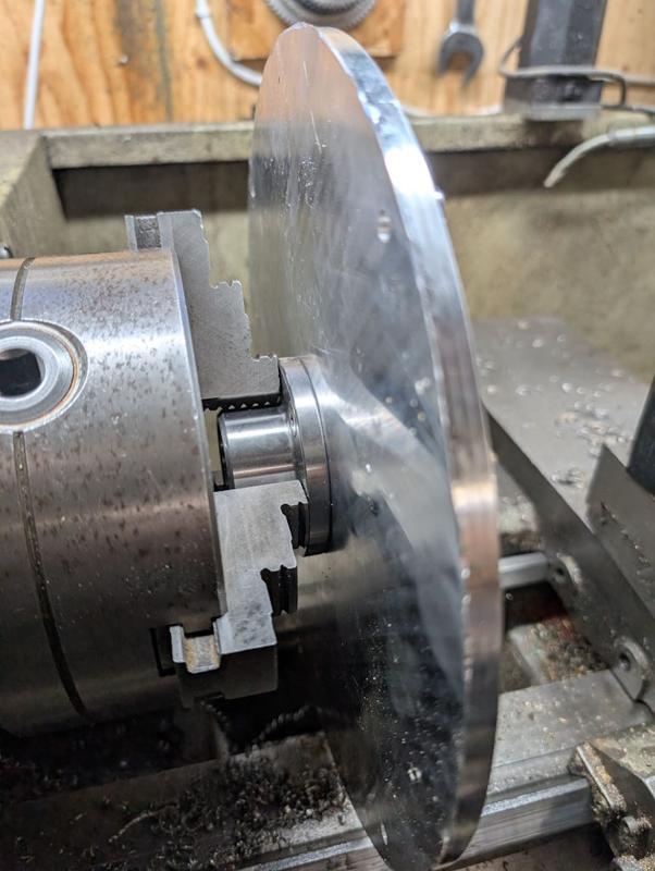
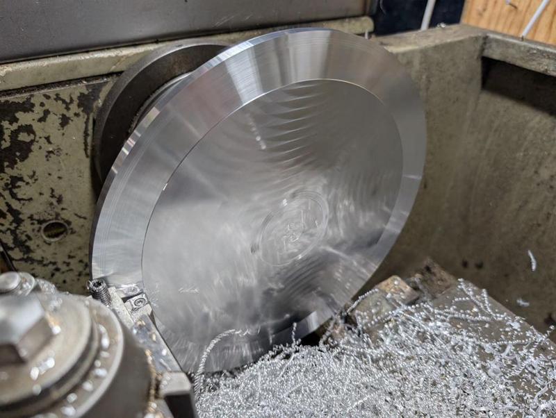
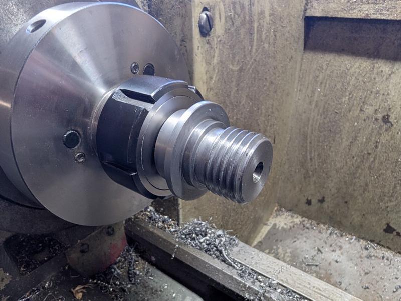
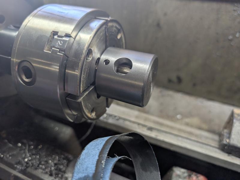
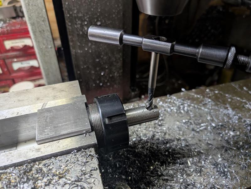
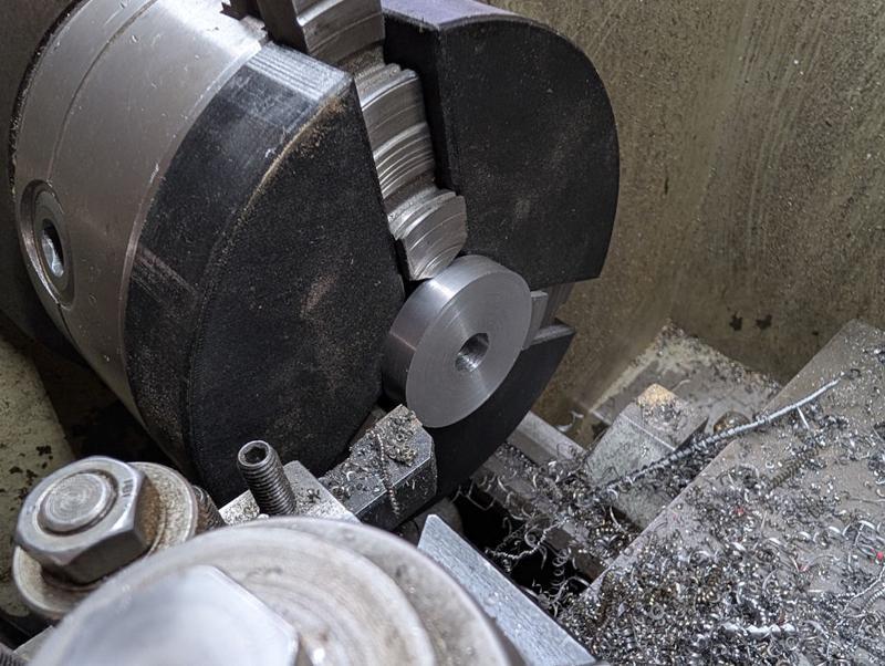
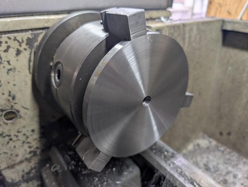
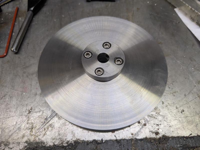
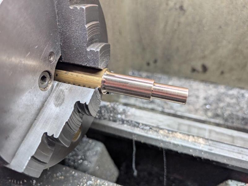
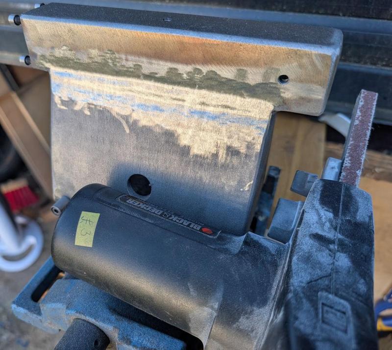
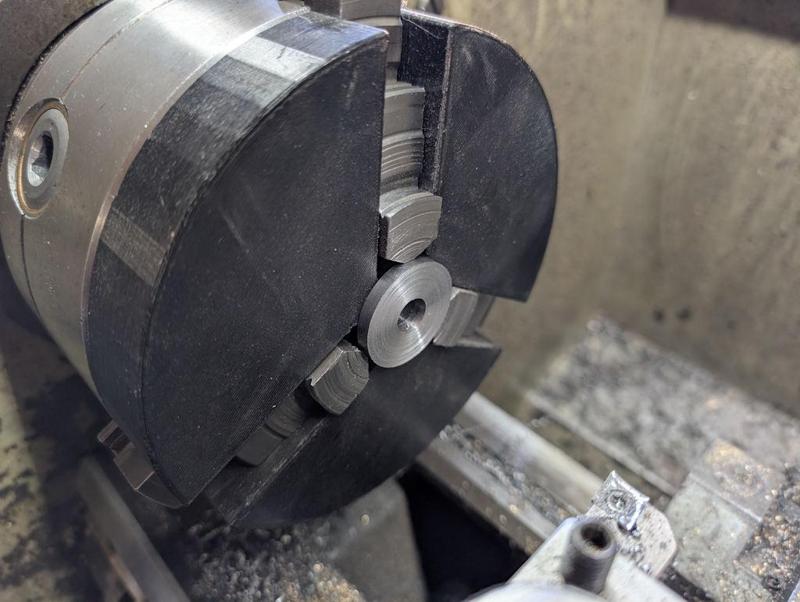
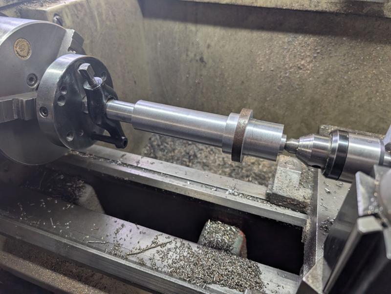
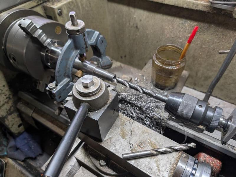
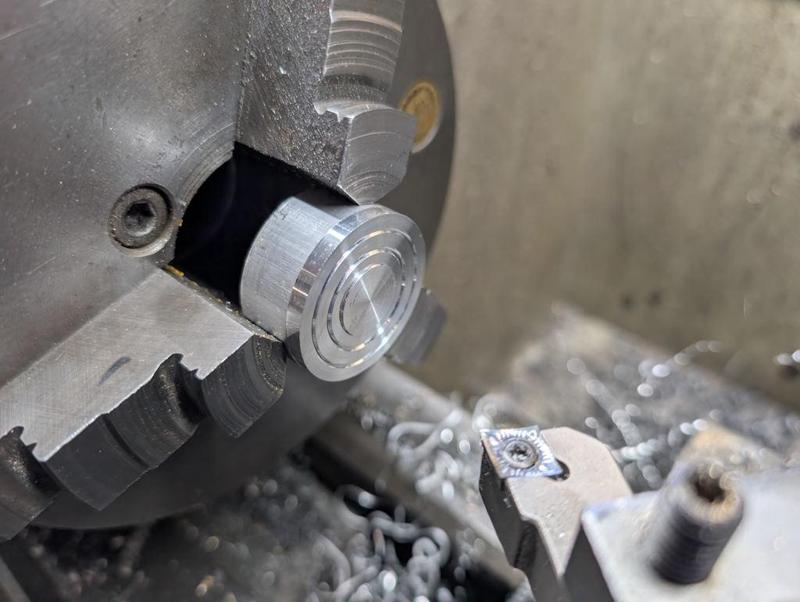
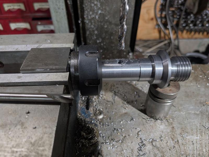
The outside surface of this part has some light surface rust. Since it was a short piece when I first started working on it, I couldn't turn the outside surface (as it was gripped in the jaws). I don't need a turned finish, I just want the rust gone. Rather than making something custom to hold on the inside bore, I thought I'd make use of the stub spindle I made a few days ago:

2025-12-27-07-spindle-in-collet_800.jpg


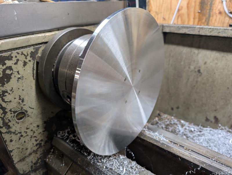
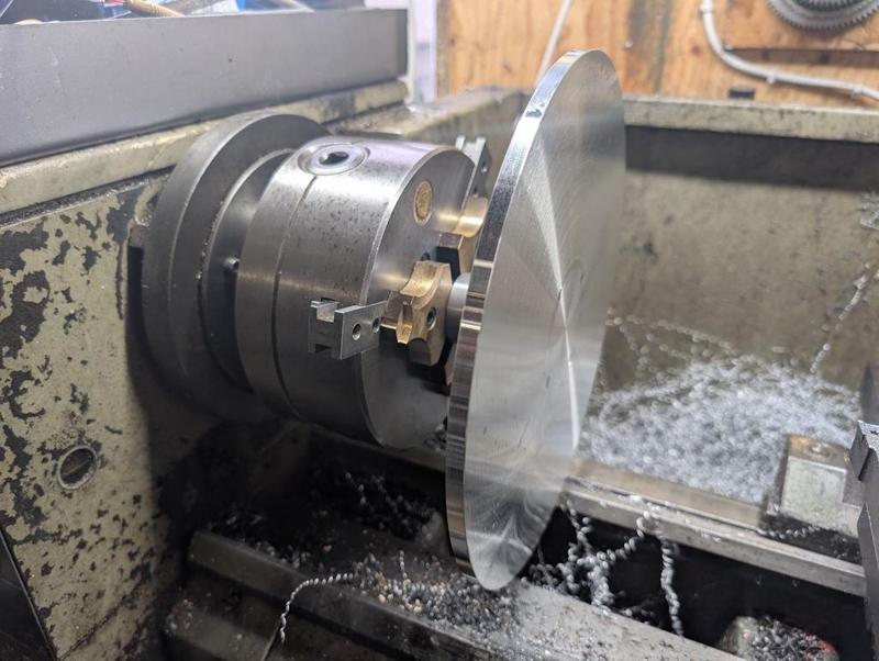
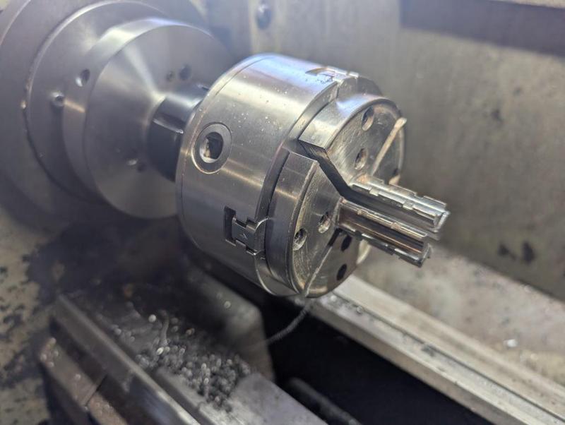
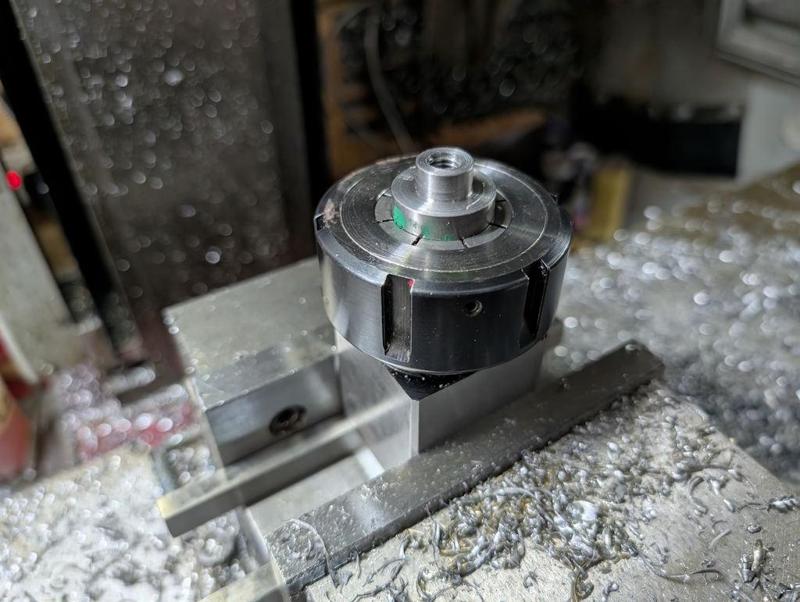
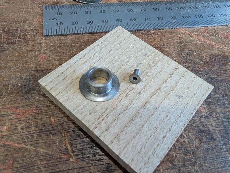
I fitted one of my woodworking chucks to that spindle and fitted some jaws that I recently bought second-hand on ebay. Conveniently, they're designed to hold on a 30 mm bore:

2025-12-27-08-ebay-jaws_800.jpg


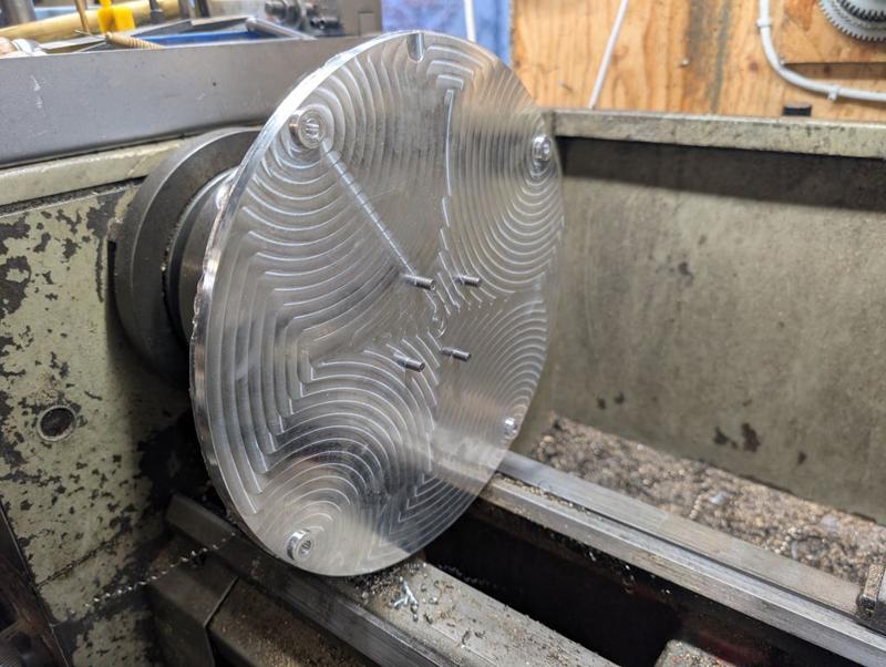
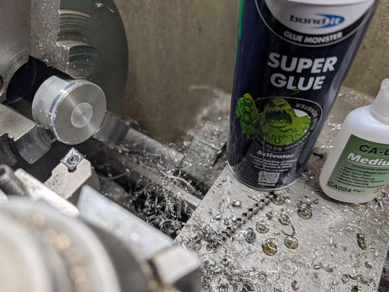
I don't think that would be a very good set-up for taking any substantial cuts with a lathe tool, but it was fine for spinning the part round and cleaning up the outside with 240 grit emery cloth:

2025-12-27-09-cleaning-outside_800.jpg


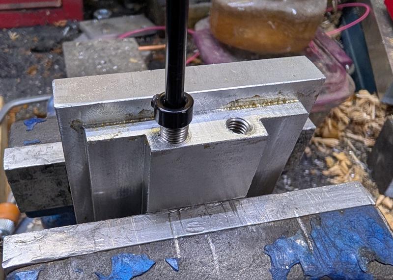
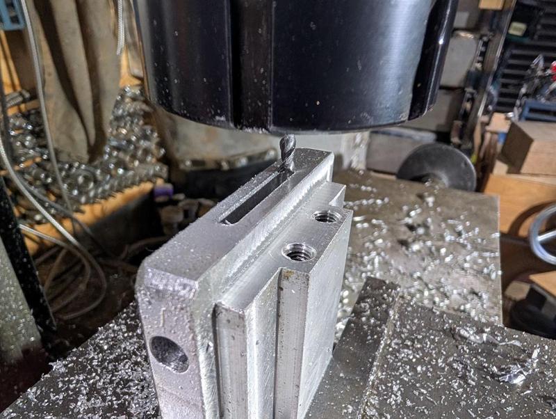
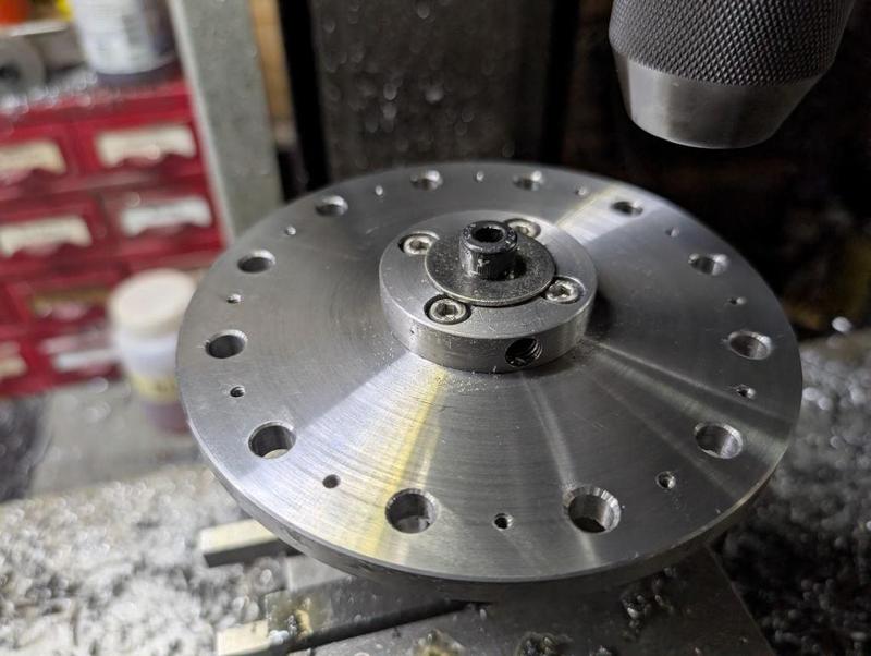
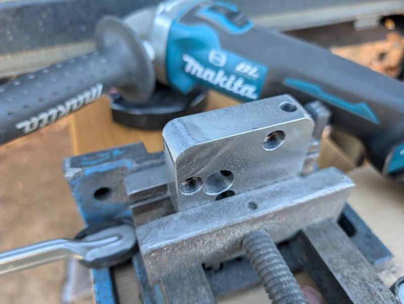
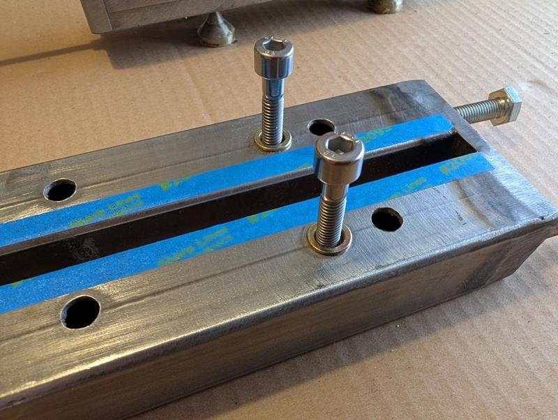
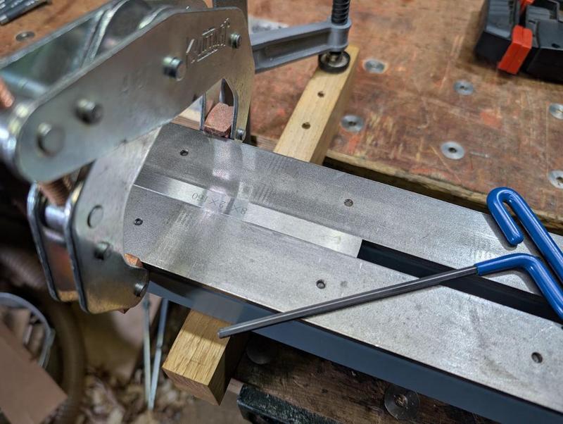
The other part already had a smooth outside surface as it had been given a skim cut on the lathe, but it still needed the cross holes, this time a 16 mm hole all the way through and a smaller M5 hole half-way through:

2025-12-27-10-cross-drilling-nut_800.jpg


That M5 hole will have a grub screw in, which will lock a bit of threaded rod into the tapped hole in the bottom; removing the M6 blanking plug in the outer part will allow access to the grub screw if I want to remove the threaded rod later.

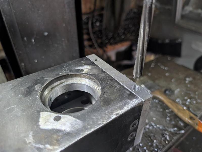
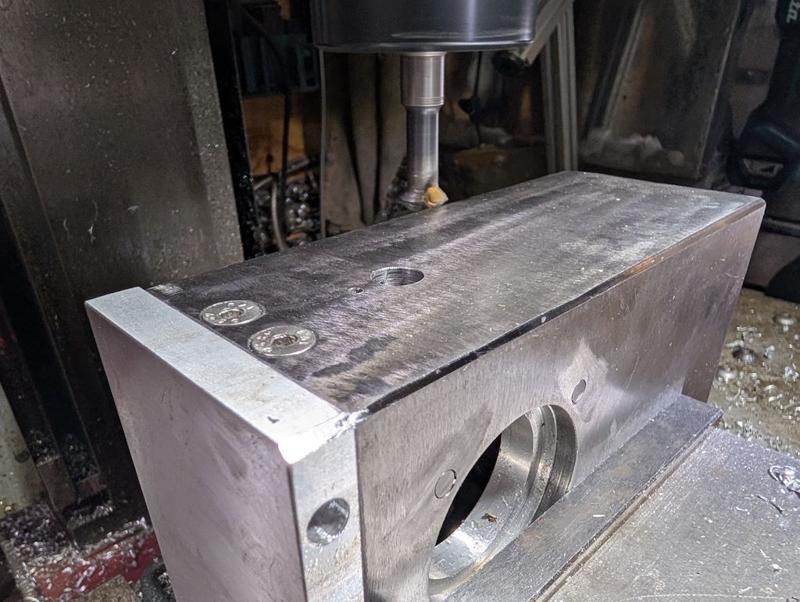
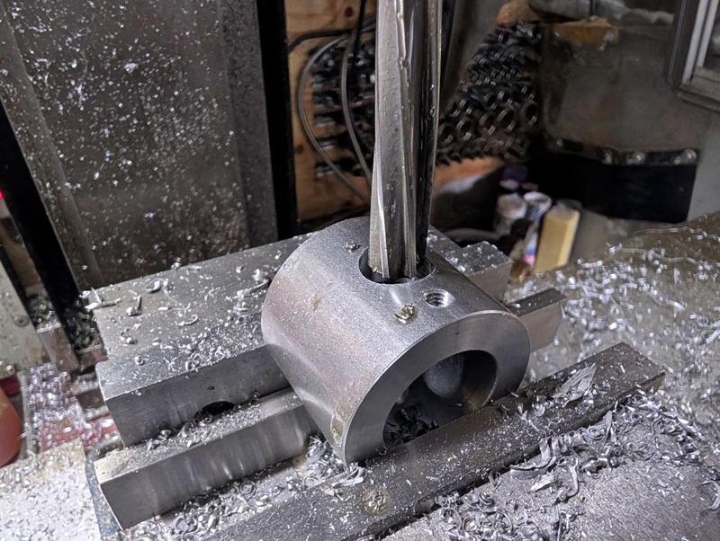
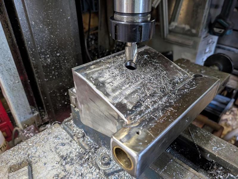
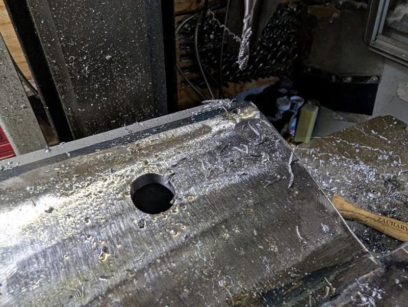
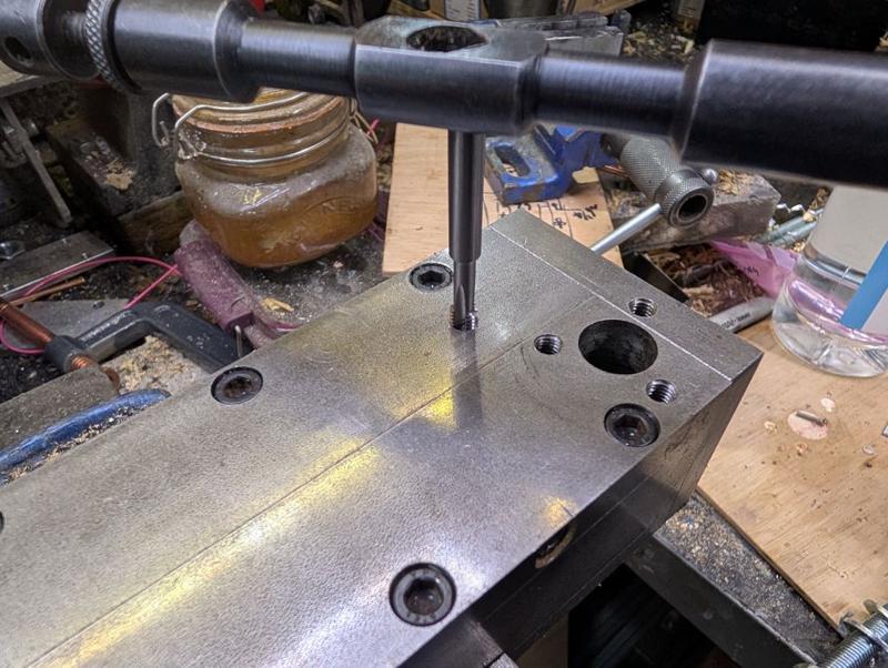
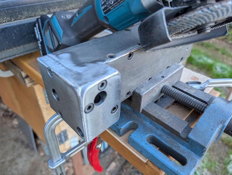
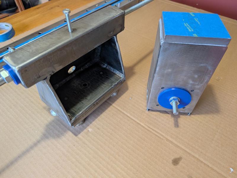
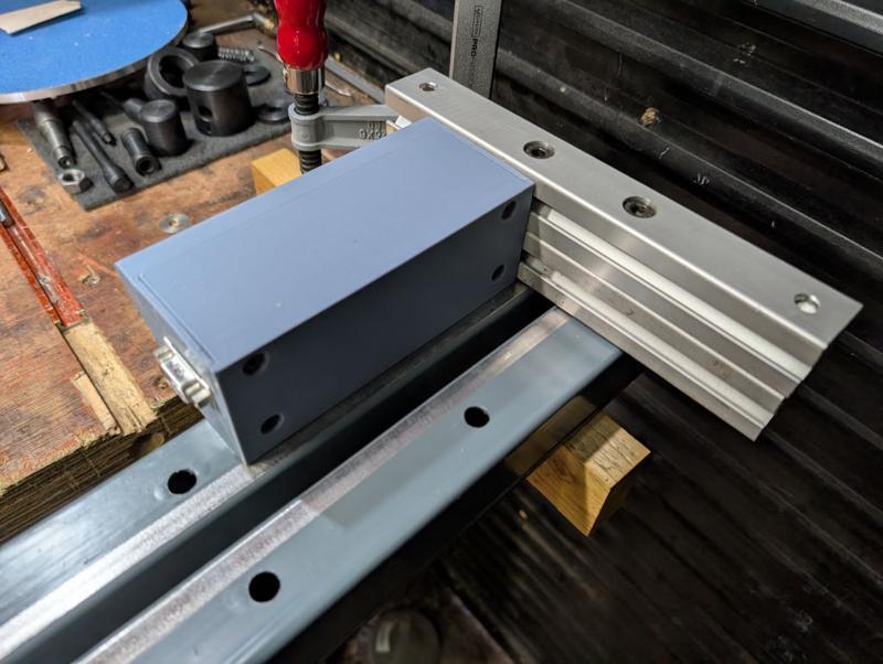
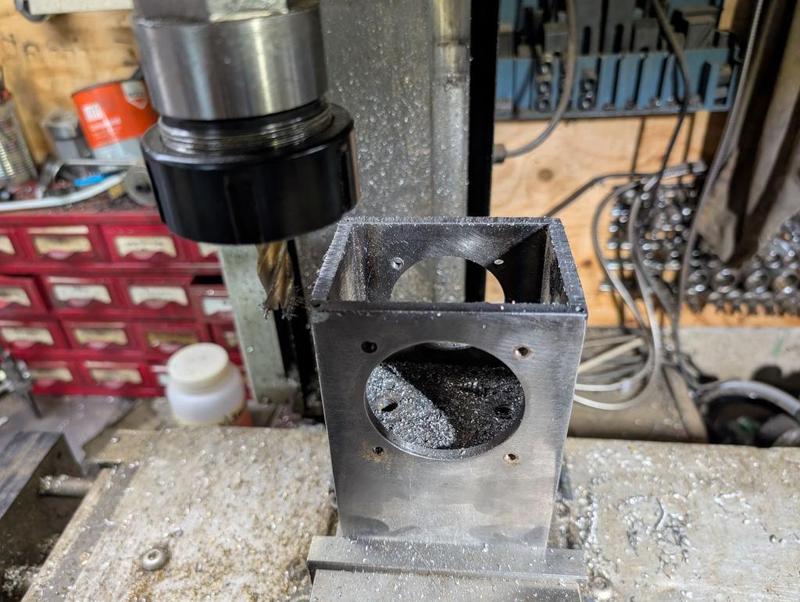
The next job was to work on the tailstock. This needed a 20 mm hole drilled in the rear face. I say drilled, but I had to use slot drills and end mills for this job as the surface is sloped and hence a drill bit wouldn't have worked.

2025-12-27-11-milling-hole-in-tailstock_800.jpg


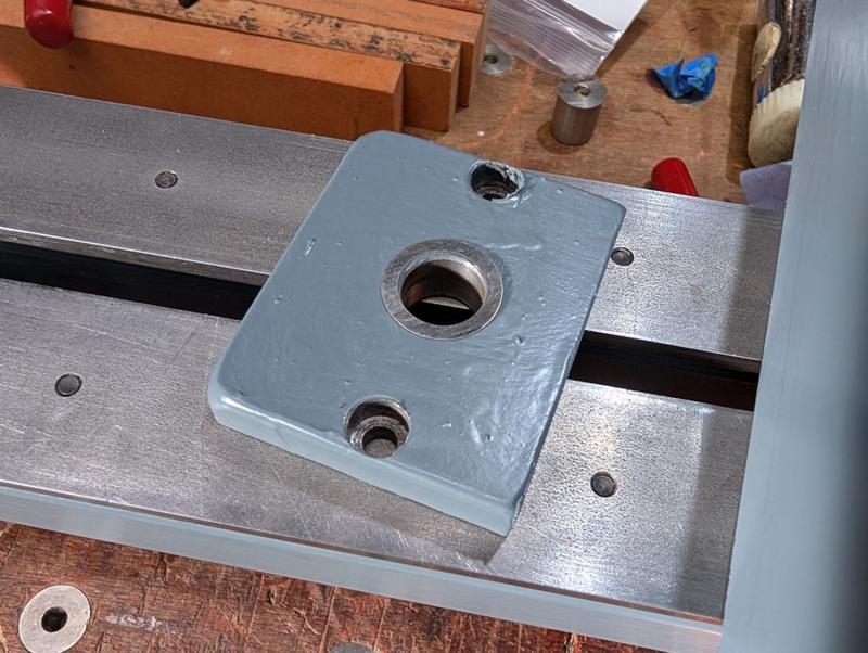
While I had it clamped in the mill vice, I also drilled and tapped an M5 hole down in the corner:

2025-12-27-12-tapping-hole-in-corner_800.jpg


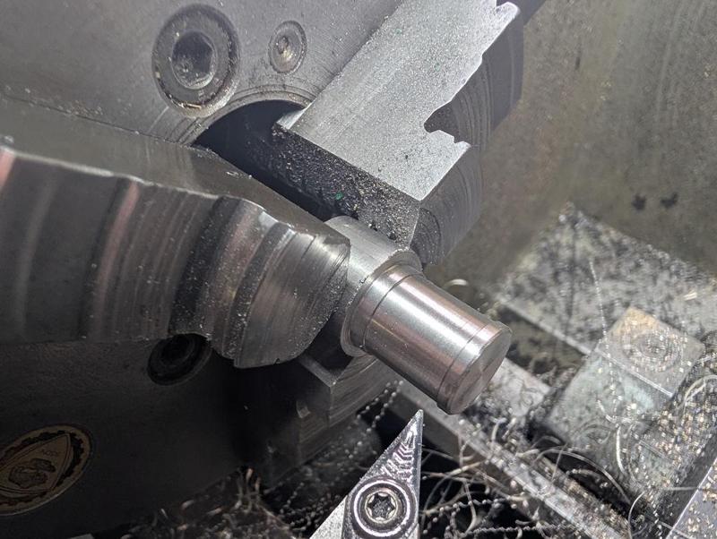
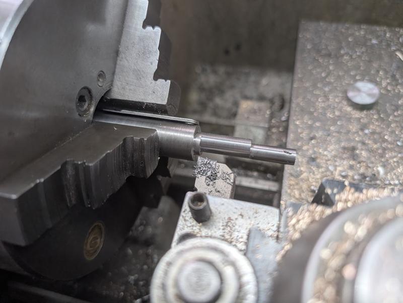
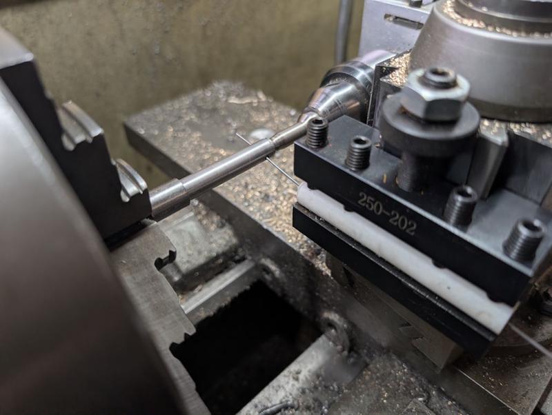
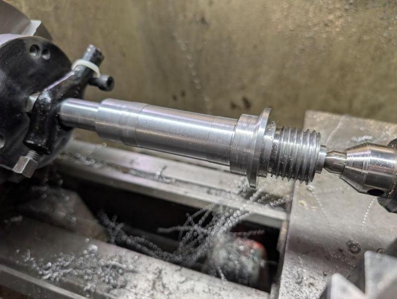
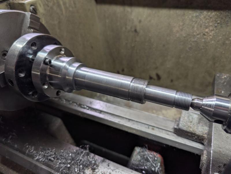
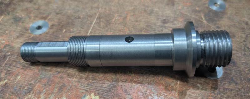
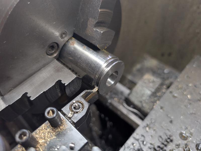
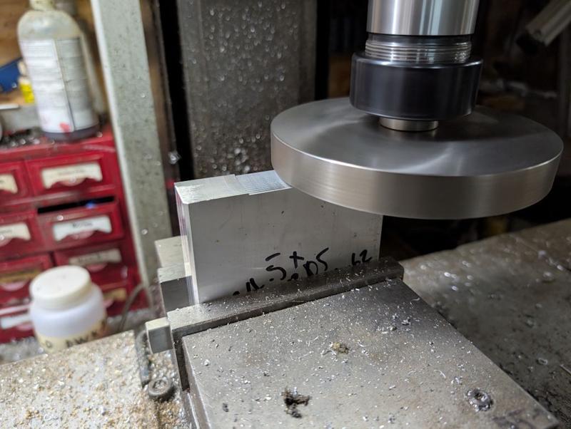
The final significant job was the cam. This started off as 20 mm EN1A, which got turned down to 16 mm for a bit and then turned down to 12 mm for a bit. The tailstock live centre was then removed and the end got an M5 tapped hole made in the end:

2025-12-27-13-shaped-and-tapped-cam_800.jpg


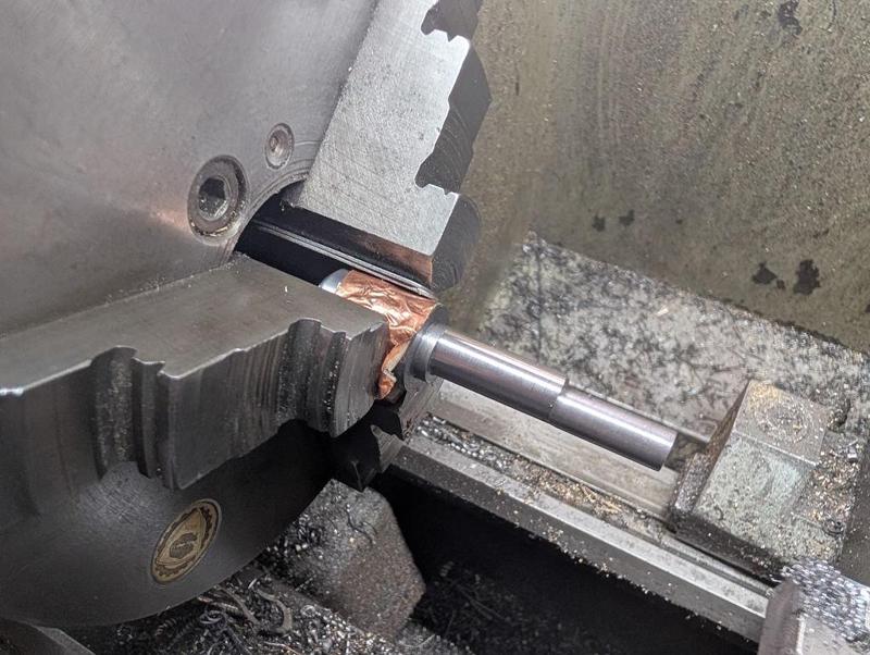
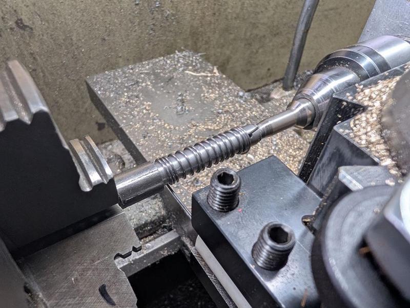
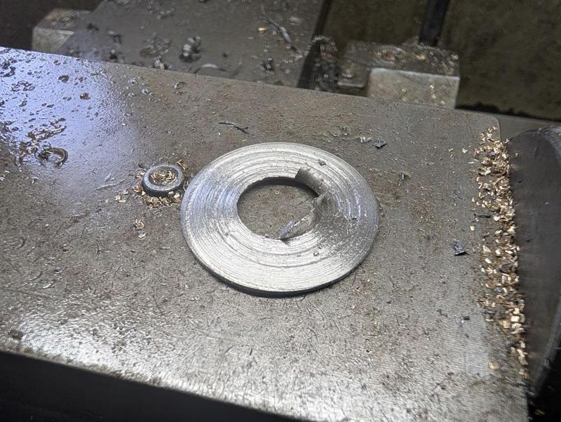
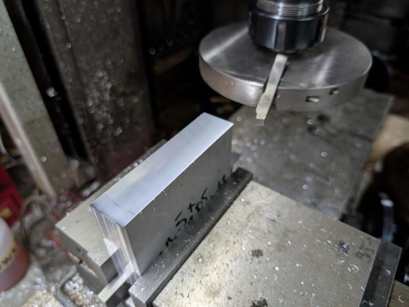
It then got remounted in the lathe but with a couple of feeler gauge sheets (totalling 1 mm thickness) in between one of the jaws and the part. I could then skim most of that 16 mm diameter down a bit more, resulting in an offset section that will lift and release the 30 mm diameter nut.

2025-12-27-14-cam-tapped-with-1mm-offset_800.jpg


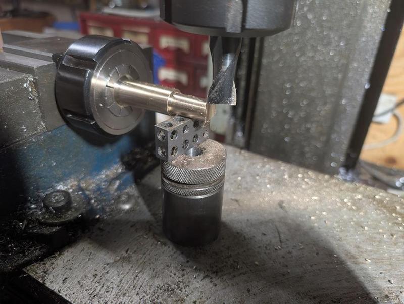
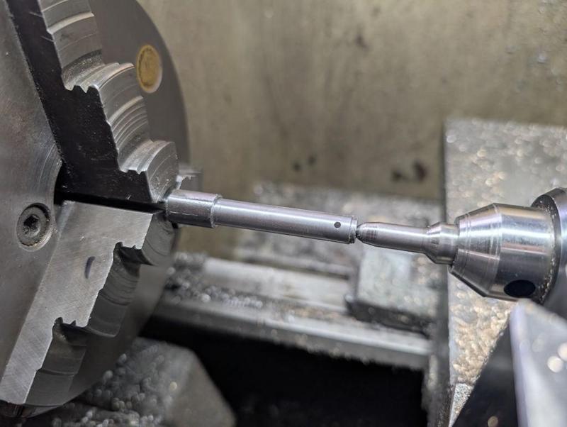
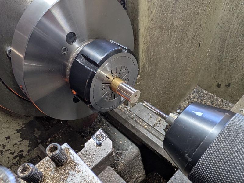
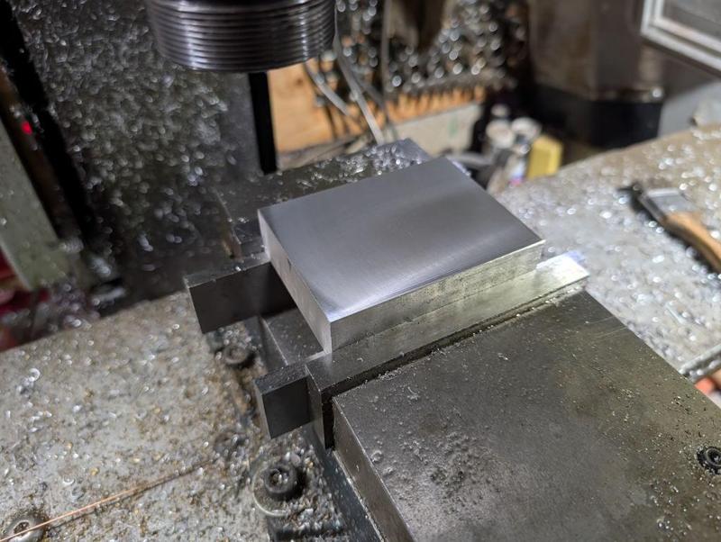
The other end got mounted in a collet and tidied up a bit and then it got taken over to the milling machine to gain a tapped cross-hole:

2025-12-27-15-tapping-other-end_800.jpg


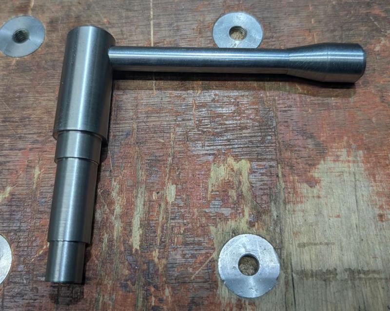
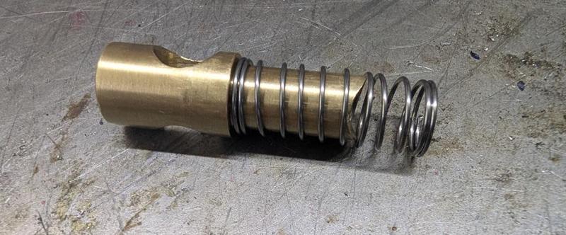
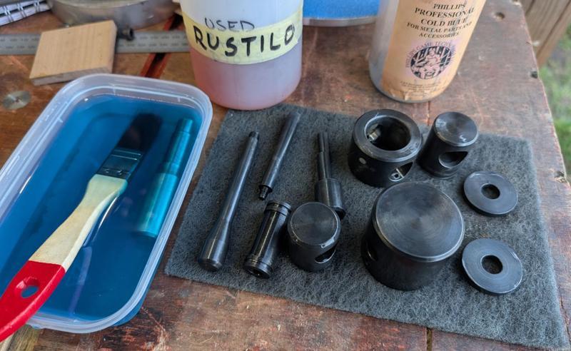
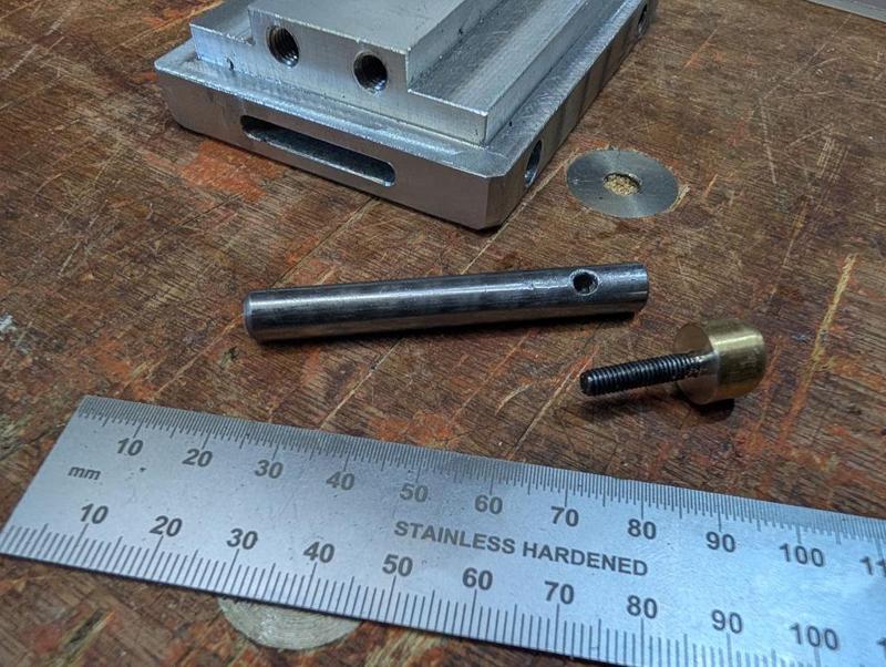
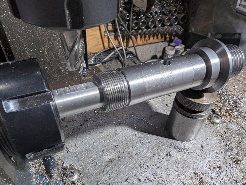
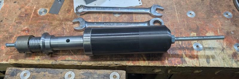
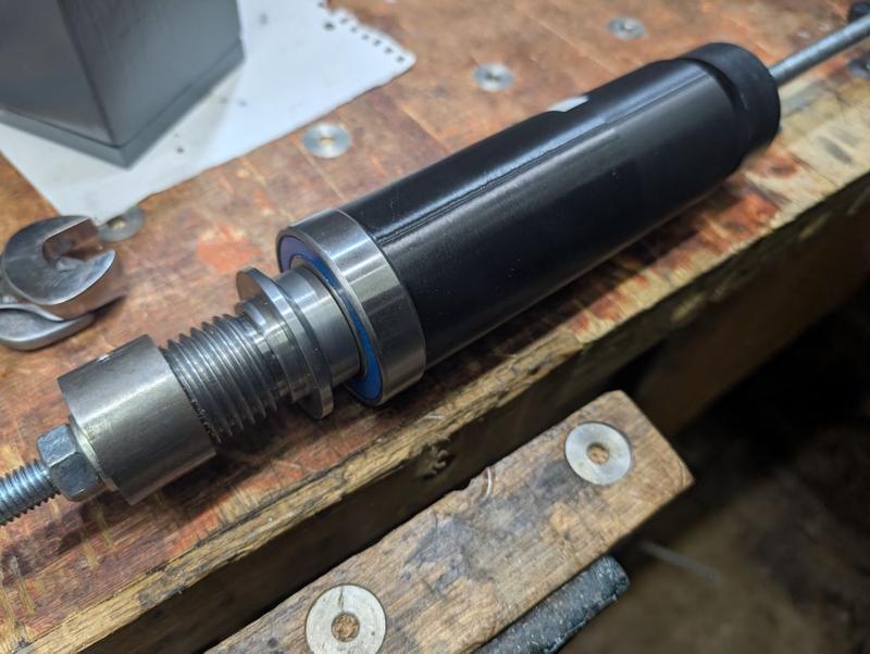
Without taking any photos, I made a couple of other simple pieces: a 10 mm shaft with an M8 thread on each end and a 16 mm tapering knob with and M8 tapped hole in the end:

2025-12-27-16-all-the-cam-bits_800.jpg


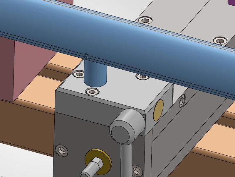
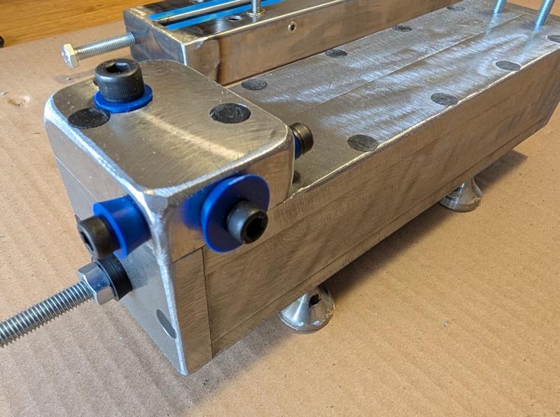
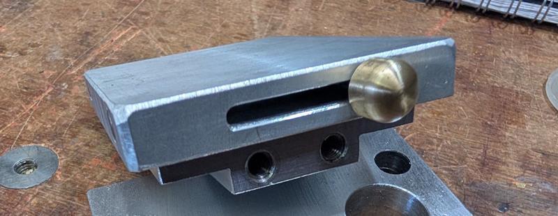
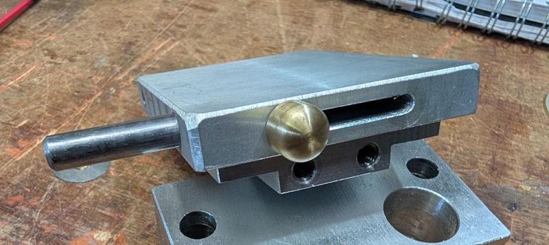
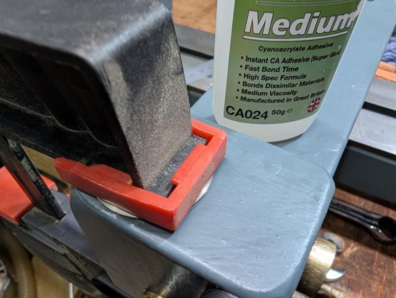
They get assembled like this:

2025-12-27-17-assembled-cam_800.jpg


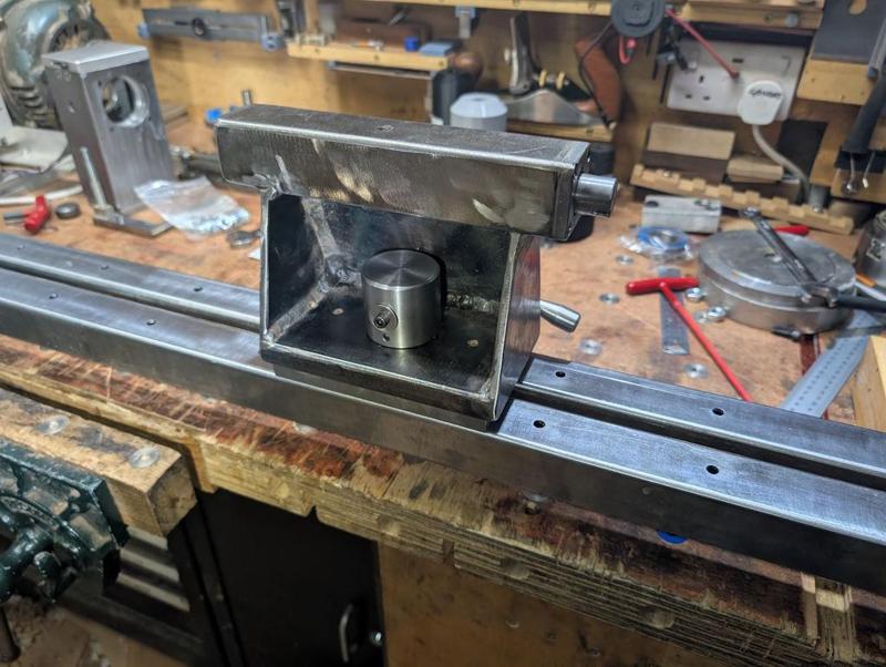
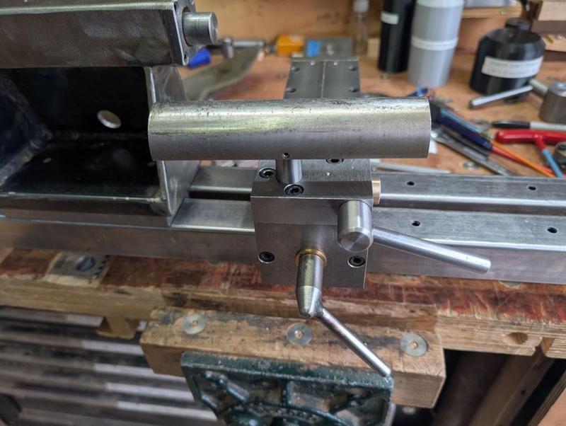
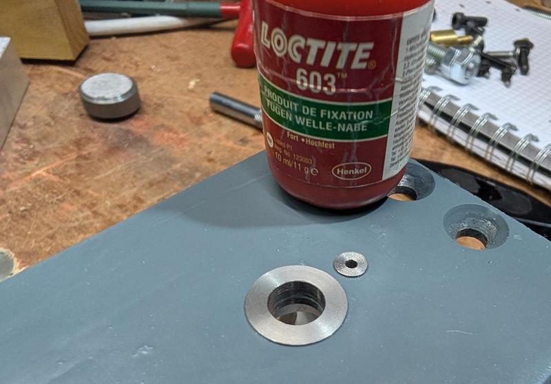
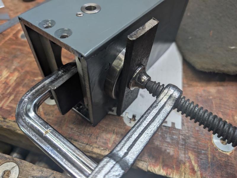
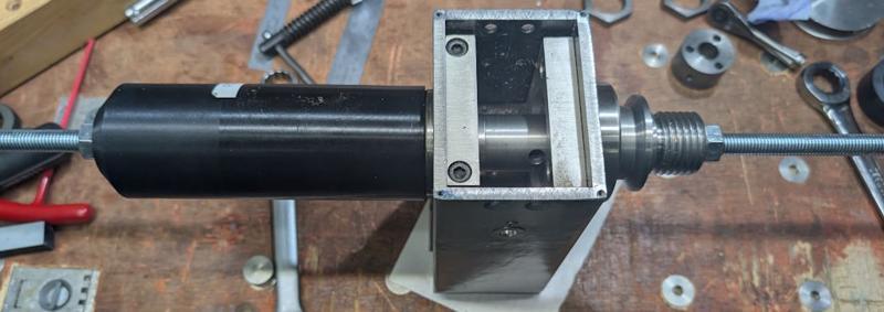
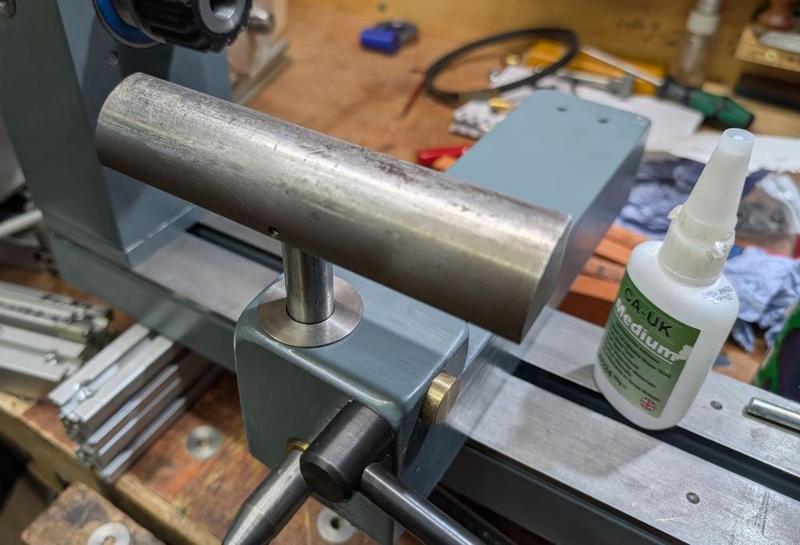
I also made a very simple small stub shaft (just a bit of 10 mm steel with a counterbored hole in it for an M5 retaining screw) to go into the tapped hole in the corner of the back of the tailstock. It was then time for a test drive. The lathe bed is in pieces at the moment, so I just got the welded box section pieces and clamped them on top of some pieces of wood on the bench. That was good enough to test the operation:

2025-12-27-18-test-run-on-bench_800.jpg


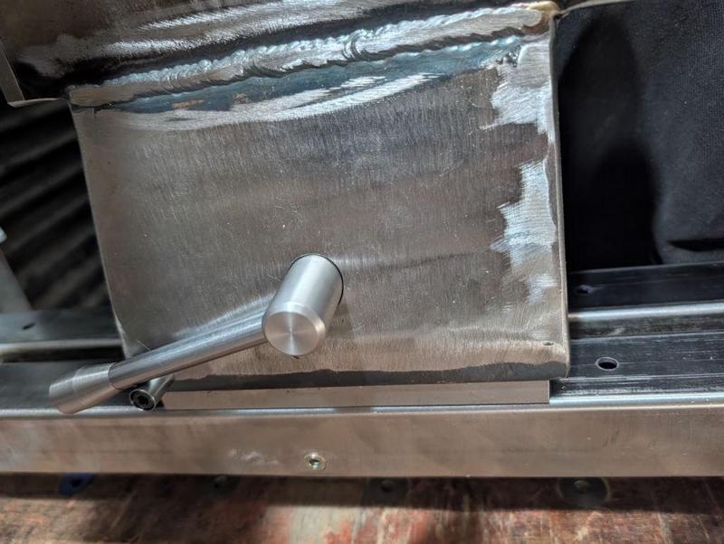
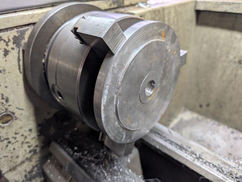
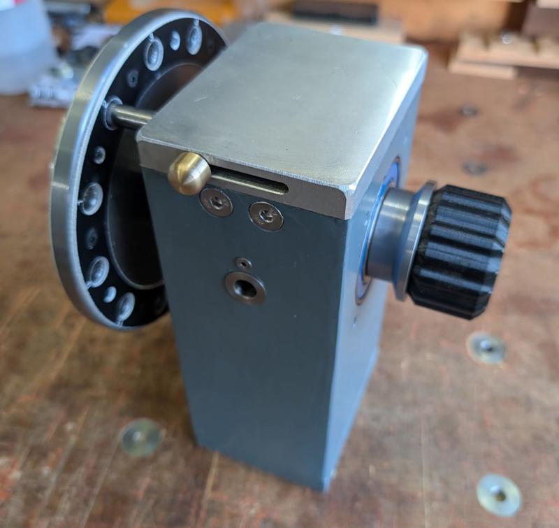
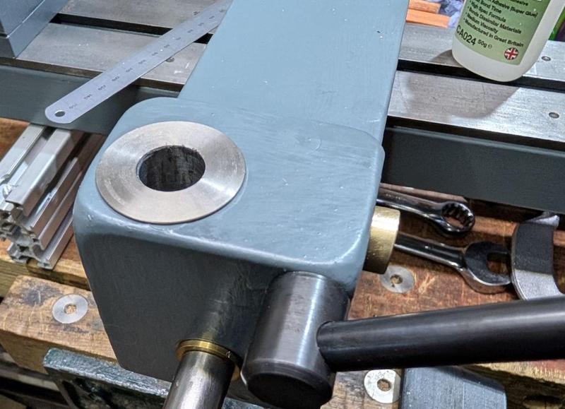
This photo from the rear of the lathe shows the cam in the unlocked position, resting on that little stub shaft (which stops it dropping further down behind the lathe and potentially starting to lock again):

2025-12-27-19-unlocked_800.jpg


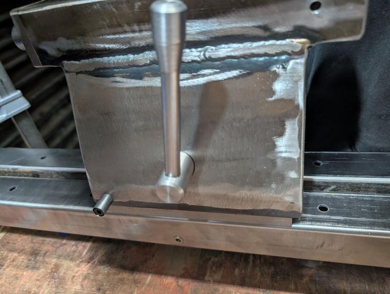
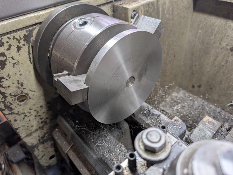
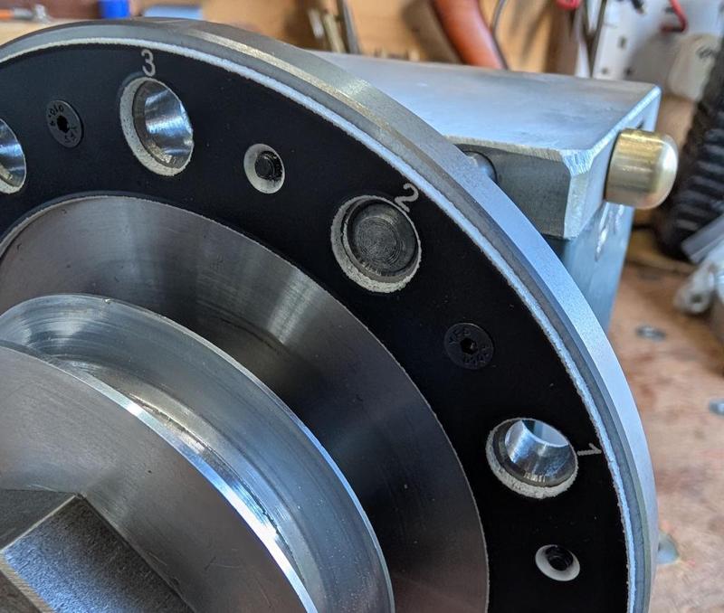
This photo shows the cam in the locked position. It seems to hold onto the bed extremely rigidly and, if necessary, it could still be rotated further if more locking force were ever required:

2025-12-27-20-locked_800.jpg


That's all the changes I'm making to the tailstock, except that I'm planning to paint it (and other parts). I might try and deal with the weld bead on the back of the tailstock before painting (if I can find a good way to get a grinder of some sort to it - my angle grinder flap disc wouldn't get in there). It's not the end of the world if I don't though.

The next job will probably be to work on the banjo. I'm thinking I might add a cam-lock to the tool post mount as well (there's already a cam-lock securing the banjo to the bed).
 
That’s a good tip, the last time I wanted to change the paper it was quite an unpleasant job really involving solvents.
So does the disc stay put well enough?
Yes it doesnt come off until you want it to. I got the idea off the yorkshire workshop guy.
 
I made a similar version of a sanding disc from MDF. I use the hook and loop method for adding / removing sanding discs. I also made a table (again MDF) from a post & mount ( similar to this https://www.axminstertools.com/axminster-evolution-series-tool-post-30mm-x-180mm-105746 and this https://www.axminstertools.com/axmi...ounting-plate-for-evolution-tool-posts-104451).

Works a treat - not something i use very often, but very useful to have when needed. Also agree that this is better for me than having a dedicated sander taking up space, when not used often.
Things I had never even thought about, yes I can see a use for that thanks.
 
I didn't feel quite ready to work on the banjo yet (still more thinking to do) so I thought I'd get on with another job. I stared with another bit of left-over 50 mm EN1A bar, which got faced, skimmed and drilled 13 mm:

2025-12-28-01-drilling-and-skimming-50mm-bar_800.jpg


After chopping it off with the horizontal bandsaw, I mounted it back in the chuck with a 3D-printed "spider" and cleaned up the sawn-off face:

2025-12-28-02-cleaning-up-reverse-face_800.jpg


Next up was a big bit of skip-dive stainless steel. That got held in the outside jaws of the three-jaw chuck:

2025-12-28-03-big-bit-of-skip-dive-stainless_800.jpg


I then cleaned up one face...

2025-12-28-04-cleaned-up-one-face_800.jpg


... then flipped it over, cleaned up the second face (bringing it down in thickness as far as I could without hitting the jaws) and then again drilled 13 mm through:

2025-12-28-05-cleaned-up-second-face-and-drilled_800.jpg


I knocked up this quick and simple jig for holding both parts on the milling machine. The end has been reduced to 13 mm for a short section and it has an M8 tapped hole in the end:

2025-12-28-06-jig-for-mill-holding_800.jpg


The lathe axis got centred on the axis of that 13 mm section and then I mounted the 50 mm piece on the jig and drilled and counterbored for M5 cap screws:

2025-12-28-07-drilled-and-counterbored_800.jpg


That part then got removed and the bigger one fitted and this time I drilled and tapped M5:

2025-12-28-08-tapped-m5_800.jpg


The last milling job for now was to mount the smaller piece on end and cross-drill and tap M8:

2025-12-28-09-cross-drilled-and-tapped-m8_800.jpg


M8 is a bit excessive for a part that thickness, but it has the advantage that the grub screw has a 4 mm AF hex socket in it, which is the same as that in an M5 cap screw or an M6 countersunk screw. Wherever possible, I'm using those types of screws on the lathe so that a single Allen key can be used for as much as possible.

Four M5 cap screws could now be used to join the two parts together:

2025-12-28-10-joined-together_800.jpg


I tightened those cap screws up as much as I could: all being well they'll never be undone.

With the two parts joined together, I mounted the assembly back on the lathe (gripping on the outside of the smaller diameter part) and (very slowly) bringing the larger part to final thickness (8 mm) and diameter (142 mm), before boring out the centre hole to 20 mm:

2025-12-28-11-turned-to-size-and-bored_800.jpg


That took most of the morning (I had to run the lathe quite slowly or it would run out of power trying to cut near the outer diameter of that stainless disc - I don't think I would have fancied doing this job with @AndyT's treadle lathe!) so I've stopped for lunch now. More to follow...
 
My treadle lathe may well predate that new-fangled stainless steel stuff - I'll have to make my bits and pieces out of brass! 😀
 
After running some errands, this afternoon saw the completion of this part. I started by making a new jig, which was simply a bit of steel with a 20 mm section turned on the end, a 24 mm section turned concentric with that (the diameter of the latter didn't matter, it just had to be concentric) and an M8 hole tapped in the end:

2025-12-28-12-making-new-jig_800.jpg


In that photo I'm parting off the bit that hasn't had any turning done on it. That "jig" got held in a collet chuck and the workpiece got clamped down to it. I then used the "PCD" (pitch circle diameter) function of the digital read-out, in combination with an 3 mm spotting drill, to mark out 24 holes, evenly spaced around the outside (on a 120 mm diameter):

2025-12-28-13-spotting-24-holes_800.jpg


They all then got drilled out 2.5 mm and then every other one got drilled out 7.6 mm, deburred with a countersink and then reamed to 8 mm:

2025-12-28-14-drilled-and-reamed_800.jpg


I put an M3 tap in the chuck but turned it by hand (there's no way I'm power-tapping M3 in stainless steel!) to turn the remaining holes into through threaded ones:

2025-12-28-15-hand-tapping_800.jpg


With all the holes drilled and reamed or tapped, that was the piece almost complete.

2025-12-28-16-all-done-on-first-side_800.jpg


I used the pillar drill with a countersink bit to deburr the reverse side of the part and then used the laser function of my new-ish 3D-printer to engrave and cut out two mirrored pieces from some 1.6 mm thick black-on-white laser laminate:

2025-12-28-17-lasering-acrylic_800.jpg


Unsurprisingly, the laser won't countersink holes, so I did that on the pillar drill:

2025-12-28-18-countersinking-acrylic_800.jpg


With that, the part is complete, both sides shown in this composite image:

2025-12-28-19-finished-with-wrong-screws_800.jpg


You may notice that the screws holding the acrylic down look a bit odd. I don't have any short enough screws to have one coming in from each side in every hole so for now I've just used a longer one in every other hole. I've got quite a few different screws to get hold of so I'll place an order with KayFast in the next day or so.

In case you haven't already guessed what this is for, this is a dividing attachment for the lathe. It'll get mounted on the rear of the spindle. There will be a sliding bar in the new lid of the headstock (using one of the two holes I drilled in the lid that had to be 60 mm from the spindle axis) that will (hopefully) slide into the holes on this dividing plate and will lock the spindle's rotation, allowing me to add features that are evenly spaced around a turned part.

2025-12-24-07-reaming-hole_800.jpg


For interest, the other hole in the lid that also had to be 60 mm from the lathe axis is just for a mounting screw. The only reason it had to be 60 mm from the lathe axis is so that I can stick an Allen key through one of the dividing plate holes in order to loosen/tighten the screw.
 
The last couple of days have been all about the new tool post clamp mechanism. There were two aims in this modification. The first was to replace the screw that is used to lock the tool post in place with a cam mechanism, which should make it possible to move the lever further away from the tool post (and hence the spinning workpiece). At the moment it points to the left slightly so I sometimes feel the need to stop the lathe before adjusting the toolpost screw just because of hand/spinning-bowl proximity.

The second aim is to reduce the height of the clamping part slightly. The current one sticks up 25 mm above the banjo; the new one 20 mm.

I started by spending quite a while with the CAD model:

2025-12-29-01-toolpost-clamp-model_800.jpg


This cut-away animation shows how the new mechanism is intended to work (this loops on my website, but I can't figure out how to make that happen on the forum):


The first job was to make the cuboid that will form the body of the tool post clamp. That started as a slice off the end of a bar of 25 × 50 mm hot rolled steel:

2025-12-30-02-block-of-hot-rolled-steel_800.jpg


It took a few hours of milling to clean all the hot rolled surfaces and reduce the size down to 20 × 49 × 70 mm, after which I had this shiny block:

2025-12-30-03-lots-of-work-to-square-it-up_800.jpg


This morning I started by drilling the hole in the end of the block (through which the brass clamping piece will slide). That was relatively straightforward, being a 12 mm hole to 49 mm depth and a 16 mm hole to 39 mm depth:

2025-12-30-04-hole-in-end_800.jpg


The holes in the top surface were also quite straightforward: three counterbored holes for M6 cap screws and a reamed 16 mm hole intersecting with that first hole I drilled:

2025-12-30-05-holes-in-top_800.jpg


The clamping piece was made from brass (which seems to look like copper in the next photo, but that's just the lighting/camera being odd). The body got turned down to 16 mm and the end turned down to 12 mm:

2025-12-30-06-brass-that-looks-like-copper_800.jpg


I did a quick test fit in the steel block to make sure it was looking okay before I took it out of the lathe's chuck:

2025-12-30-07-test-fit_800.jpg


To match the curve in the tool post's shaft, I mounted the brass piece in the milling vice with a collet chuck and used a 16 mm end mill to cut into the end:

2025-12-30-08-milling-curve-in-the-end_800.jpg


I wanted to drill the last hole in the big block with the two parts together. If I pushed the brass piece into the hole and just attacked it with a drill bit, the hole could end up at the wrong angle and more than likely in the wrong place as well. If I put a 16 mm bar in the hole and clamped the brass piece to that, it would ensure the right orientation but the brass clamp would never move deep enough into the hole to actually clamp.

As an alternative, I dug out an off-cut and turned a section down to 16 mm before reducing the central portion a bit further (to 15 mm diameter):

2025-12-30-09-machining-a-spacer_800.jpg


That half millimetre reduction in radius means that, when clamped together, the hole in the brass piece was drilled with a bit of a protrusion into the tool post hole:

2025-12-30-10-clamped-in-mill-vice-for-cross-hole_800.jpg


The first two parts complete:

2025-12-30-11-first-two-parts-done_800.jpg


Making the cam followed much the same process as the last one, with the first two diameters and the tapped hole in the end done as usual in the lathe before making the cam with some feeler gauge pieces shoved between one of the jaws and the part:

2025-12-30-12-making-the-cam_800.jpg


After drilling and tapping the cross hole for the tommy bar and finishing the bar to length, I found that the cam needed a bit of tweaking, so I put it back in the lathe (with some copper tape protecting the part from the jaws) and took 0.1 mm deep cuts at a time, testing with the rest of the assembly and the tool post after each cut:

2025-12-30-13-modifying-the-cam_800.jpg


With that, all the core parts were made and it was clamping the tool post very effectively. However, when the cam is unlocked, there's nothing stopping the brass clamping piece wandering into the tool post hole and hence stopping the tool post from being inserted. Fortunately, I'd thought of that beforehand: what it needs is a spring (if you go back to the cross section animation at the start of this post, you'll see a convenient gap has been left for a spring to sit in).

A few years ago, I made a spring calculator for calculating the right arbor size for making a custom spring out of piano wire. Despite having made that calculator, I've never actually made a spring before: I always intended to but never really had a need for a custom spring. This seemed the perfect opportunity.

The process is very simple. You set up the calculator for the diameter of piano wire you have, pick a target diameter and other parameters that matter to you (e.g. pitch, length) and it tells you the arbor size on which to wind your spring. The arbor is a simple bit of steel with a hole drilled through the end:

2025-12-30-14-arbor-for-spring-turning_800.jpg


The wire gets fed through something clamped in the tool post (I used a bit of plastic with a hole drilled through) and through the cross-hole:

2025-12-30-15-wire-being-fed_800.jpg


After turning the spindle a couple of times by hand to make the end coils, you engage the lead screw half-nuts (with the leadscrew set up for the desired pitch) and then keep turning the spindle by hand. Once you've got the length you want, you disengage the lead screw half-nuts and do a couple more turns for the other end:

2025-12-30-16-wound-spring_800.jpg


After trimming off the excess with some heavy duty side cutters, I slid it onto the brass bit and it was a perfect fit (so the calculator seems to have got the arbor size spot on):

2025-12-30-17-spring-on-brass-bit_800.jpg


After assembling it again, I put the tool post clamp block in the bench vice and tried it out. If you look into the hole in the first half of this short video, you can see the brass clamp moving in (under the cam force) and out (under the spring force):


The last thing to do was drill and tap an extra hole (located with a transfer punch after tightening the other two screws) in the banjo:

2025-12-30-18-tapping-extra-hole_800.jpg


Complete:

2025-12-30-19-fitted_800.jpg


I may shorten the brass clamp (so it doesn't stick out the side as far) at some point, but I'm going to leave it as-is for now. It's not doing any harm as far as I can see and it'll give me something to grab onto if I ever need to for some currently unforeseeable reason. I'd also like to round off a few sharp corners at some point (although I can't got that far as there are a lot of screw head counterbores that are very close to the edge).
 
If you hadn't already made a lot of excellent wooden bowls, I'd be thinking this lathe project was just an excuse for an equally impressive series of ingenious metallic upgrades. But you have, so I'll just shut up and admire your ingenuity and forward planning!
 
If you hadn't already made a lot of excellent wooden bowls, I'd be thinking this lathe project was just an excuse for an equally impressive series of ingenious metallic upgrades. But you have, so I'll just shut up and admire your ingenuity and forward planning!

Thanks Andy. It's one of the things I quite like about a project like this: there are endless opportunities for little tweaks & upgrades & in many cases I can modify one part without risk: if it doesn't work I can go back to how it was before. Taking the risk away gives me a bit more freedom to experiment with different ideas.

When I first made the lathe, I really didn't expect to use it much at all so I did what felt like the minimum to get a relatively capable lathe. Having made all the bowls the opportunities for upgrades became more apparent and, having raised all that money for charity, it felt a bit more worth it.
 
This morning I did a little bit of tidying up and removing of sharp edges. I started with the slightly shabby area on the back of the tailstock. After a bit of angry grinding with a flap disc (which wouldn't go right into the corner), I finished it off with my bargain basement Black & Decker power file:

2025-12-31-01-cleaning-up-tailstock-with-powerfile_800.jpg


The tool post clamp block I made yesterday had its rear corners roughly rounded over using a 40 grit flap disc:

2025-12-31-02-rounding-rear-edges-on-clamp-block_800.jpg


It then got clamped firmly (and possibly finally) back onto the banjo and I went round all the corners with the flap disc:

2025-12-31-03-rounding-over-banjo-generally_800.jpg


Once that was all done, I couldn't feel my thumb any more so I retreated inside to warm up!
 
That's the second appearance of a B&D powerfile today! And to think that was offered one about 15 years ago and said no as I thought I would never need it... Then again, I've not made my own lathe or camping trailer! 😏
 
That's the second appearance of a B&D powerfile today! And to think that was offered one about 15 years ago and said no as I thought I would never need it... Then again, I've not made my own lathe or camping trailer! 😏
I was thinking about this earlier, and I can't recall using it at all in over 20 years. I have a special drawer for useless-but-functional stuff. Turns out that a 1960's electric carving knife has FAR more use than a power file!
 
I have a special drawer for useless-but-functional stuff.

I've got one of those too. It's clearly labelled "Where Tools Go To Die".

Turns out that a 1960's electric carving knife has FAR more use than a power file!

I use mine quite often, but only for metalwork. I don't think I've ever used it on wood. They're really useful for getting into little places that an angry grinder won't get to. I gather Graham Hawkins uses one a lot for his metal sculptures.

They don't half go through belts quickly when you're grinding steel away with them though! Having said that, given that it cost my father-in-law £3 from a car boot sale and me nothing at all, I can't really begrudge the cost of the belts.
 
I used my car boot powerfile loads for my machine resto work, they certainly made the motors to last, it would probably still be going if I hadnt stood on it.
 
Over the last couple of days I've been painting the lathe (it only took me two years!)

I started by applying some masking tape anywhere that was a running metal-on-metal surface. For the welded box section frame, that's just a narrow strip down the middle of the bottom where the locking washers will run:

2026-01-02-01-masking-washer-running-surface_800.jpg


The top surface was originally a running surface but since I've attached the extra steel plates on top (which won't get painted), it no longer has anything running along it.

The tailstock and headstock got the significant holes filled in with some 3D-printed cones, most of the tapped holes filled with sacrificial screws and the bottom surfaces masked:

2026-01-02-02-plugged-and-masked_800.jpg


The banjo was the most complicated, with little black plastic plugs that fit into the hex socket in the cap screws and cover them up, a pair of printed cones on some threaded rod for the banjo locking bar holes and a very complicated arrangement of four interlocking cones to fill the holes for the toolpost clamp mechanism:

2026-01-02-03-lots-of-plugs_800.jpg


Most of those black plastic screw covers will stay there semi-permanently, only coming out if I ever need to dismantle the banjo. The two on the rear cover (not visible in that photo, but equivalent to the one that's lowest down in the image above) will get removed (as the rear cover has to be removed to fit the locking mechanism).

Once everything was masked off, I applied some paint, using the same "Slate Grey Satin" Jenolite Directorust paint that I used on the control cabinet for my heat treatment oven as I had most of the tin left.

2026-01-02-04-paint_800.jpg


I applied two coats, then left it overnight, then sanded some areas a little with 180 grit wet-and-dry, then applied a couple more coats in the sanded areas. Now I'll leave it overnight again before seeing whether I can remove the masking tape and printed bungs without doing any damage!

In the meantime, I've also done a couple of other minor jobs. The first was to clean up the thick washers (that run on the bottom of the box section as mentioned above). When I originally made them (just trying to knock the lathe together as quick as possible), I faced one side and then parted off to length. The parted-off side was a bit shabby, so I put the washers back in the three-jaw chuck (with a 3D-printed spider) to clean up that face:

2026-01-02-05-cleaning-up-washer_800.jpg


The last job I did today was to treat most of the unpainted steel parts with cold blue and then oiling them with some rust protection:

2026-01-02-06-cold-blue_800.jpg


The one that's still in the blue solution refused to change colour for some reason. It had multiple cycles of cleaning (with acetone and with wet-and-dry paper followed by acetone) and multiple long soaks in the cold blue solution but it was having none of it. I can only assume it's a different grade of steel to the other parts (although it turned really nicely, implying EN1A like the rest). In the end I gave up and just applied the rust protection oil.
 
A few minor jobs have been ticked off the list today, along with the start of something bigger.

The first job I did was skim and face some brass bar and then drill and tap a blind M4 hole in the end:

2026-01-04-01-machining-brass_800.jpg


That then got parted off, held in a collet and the other end rounded over, first with a chamfering tool and then with a file. A bit of threaded bar (actually an M4 cap screw with the head cut off) got fitted into the threaded bit with some Loctite 603 to hold it in place. It's a bit of an odd screw in that there's nothing to grip on the head in order to turn it:

2026-01-04-02-brass-with-steel-screw-and-bar_800.jpg


It gets screwed into the threaded cross-hole in that bit of 8 mm silver steel. I tightened it in place using an ER32 collet block to grip on the outside of the brass. All being well, it won't have to be undone. Those two bits get fixed together in the lid, thus:

2026-01-04-03-retracted_800.jpg


The brass "knob" can be slid to the left to make the silver steel bar poke out the side of the lid:

2026-01-04-04-locking-position_800.jpg


That bar will (hopefully) engage with the holes in the dividing plate I made last week and is the other half of the dividing mechanism. I won't be able to find out whether I've made it (and the dividing plate) right until the headstock is fully assembled.

I'm thinking of 3D-printing a little cover to go over the slot (probably just magnetised in place) to stop sawdust getting in there. The design still needs a little thought to make it look relatively neat.

Another simple job was to make a couple of little top-hat washers out of 303 stainless steel:

2026-01-03-00-two-little-top-hat-washers_800.jpg


Those will get glued (with Loctite 603 probably) into the holes in the front of the headstock (the one for the tommy bar and the one for the screw that will hold the cover for the first hole in place). The only reason for these washers is to stop the rotating cover from rubbing on the paint.

The last job I did today was to rough out the overall shape of yet another spindle (hopefully with the Morse taper cut properly this time) after the steel I had ordered arrived yesterday:

2026-01-04-05-roughed-out-spindle-again_800.jpg


I doubt I'll manage to do any more on the spindle until Friday now, but all being well I'll get the spindle finished at the weekend and can start assembling the headstock (and then try out the dividing mechanism).
 
I was thinking about this earlier, and I can't recall using it at all in over 20 years. I have a special drawer for useless-but-functional stuff. Turns out that a 1960's electric carving knife has FAR more use than a power file!
Coincidentally, there's been a bit of a discussion on the MIG welding forum today about powerfiles.

Some relevant quotes:

marlinspike said:
We bought a Makita die grinder to take down welds on our car resto but have found a Black and Decker powerfile to be a better tool for the job. The die grinder is heavy and scary; the powerfile slower but easier to use and more versatile as you can remove rust and paint. The powerfile is the tool I wish I'd bought on day one and the big die grinder one I probably wouldn't buy again. I have just bought a Lidl £15 one though, but it's smaller and a lot less scary looking.

Seadog said:
I owned a B&D powerfile for over 20 years before I thought use use it doing doing sone wood butchery for my neighbour's art installation. What an amazing tool. I still have it 35 years after getting it as part of a workshop clearance, it wasn't new then.

marlinspike said:
I've never seen Lidl or Aldi do the powerfile knock offs unfortunately. I'd definitely get one or even two if they were under £20. We wore out the rubber cylinder on the end of the arm on ours; replaced it because it was only a fiver a couple of years ago but it's around a tenner now. I snapped up a nearly new powerfile on ebay a couple of years ago just to alternate with the old one and so I was never without one.

Had a quick look and Toolstation have the B and D one for £50, with the other brands not much cheaper. The cheap Silverline ones seem to be unavailable now.

julianthegypsy said:
I have the B&D one that I paid £50 for seven years ago after the aldi one that I bought to see if it would come in useful finally wore out. Never regretted it, it comes in useful all the time where I can't get in with an angle grinder and flap disc. I use the cheap belts from screwfix and have never had a problem with them.

They're obviously a lot more popular among metalworkers than woodworkers.
 
I got on with the spindle today. Here it is after getting the critical outside turning done (i.e. the bearing surfaces and the chuck register):

2026-01-09-01-critical-turning-done_800.jpg


The rear threads then got turned as before:

2026-01-09-02-turned-rear-threads_800.jpg


Drilling from the rear was done in two stages, a 10 mm drill and then a 13 mm drill:

2026-01-09-03-drilling-from-rear_800.jpg


Once it was in the soft jaws and I'd drilled through and then bored and reamed the Morse taper, it was with quite a sense of relief when I got the hole size about right:

2026-01-09-04-a-sense-of-relief_800.jpg


I probably could have gone a bit bigger than that (and hence allowed the centre to go a bit further in) and according to the proper Morse taper dimensions I should have. However, I wanted to err on the side of caution and I'm sure there's plenty of taper engagement for a good grip.

The last thing to do on the spindle was to cross drill for the tommy bar and (in a change from previous spindles), mill a flat for the grub screw in the dividing wheel to bear on:

2026-01-09-05-cross-drilled-and-milled_800.jpg


The finished spindle:

2026-01-09-06-the-finished-spindle_800.jpg
 
With the spindle complete, it was time to do a test assembly of the headstock. The first job was to glue the little stainless steel top hat washers into the tommy bar access holes:

2026-01-09-07-glued-in-tommy-bar-hole-inserts_800.jpg


I could then squeeze the rear bearing in, using a couple of scraps of 6 mm steel flat bar and an F-clamp:

2026-01-09-08-squeezing-rear-bearing-in_800.jpg


This was roughly the set-up for fitting the angular contact bearing onto the spindle:

2026-01-09-09-setup-for-fitting-angular-contact-bearing-to-spindle_800.jpg


I say "roughly" because I swapped the M10 threaded rod for some M12 stuff before actually pulling the bearing home. Here it is fitted:

2026-01-09-10-angular-contact-fitted-with-m12-thread_800.jpg


The spindle and angular contact bearing assembly then got pulled into the headstock (which already has the rear bearing fitted):

2026-01-09-11-pulling-spindle-into-headstock_800.jpg


I'm very pleased to say that it looks like I got the hole for the dividing bar in the right place:

2026-01-09-12-dividing-bar-works_800.jpg


The locking bar length is just right as well (although that would have been very easy to fix if not):

2026-01-09-13-dividing-bar-length-is-right_800.jpg


I still need to make the cover for the tommy bar hole and fit a couple of 3D-printed bits (the chuck key holder at the back and the slot cover at the front), but otherwise that's the headstock finished.
 
I spent the afternoon assembling more of the lathe. The first part of that was fitting the top plates that sit on the (now painted) box section bed). As before, I did that with the two plates clamped firmly onto a couple of 12 mm parallels. Those top plates form the reference for the tailstock alignment, so it's important they're parallel:

2026-01-10-01-fitting-bed-top-plates_800.jpg


With that done, I could fit the aluminium extrusion that the bed sits on, along with the control switch box:

2026-01-10-02-fitting-control-box_800.jpg


When I'd designed the banjo, I hadn't considered any impact of painting it. The brass washers that rotate in the end plates ran directly on the steel surface. Adding a normal washer isn't possible as there's a hole in the bottom of the end plates for an Allen key to access the locking grub screw. With a thick washer, that hole wouldn't line up with the grub screw location.

My simple but slightly lazy answer to this was to buy some stainless steel shim washers. I can make thin washers, but it's quite a tedious process (see later in this post). The 12 mm bore ones I could buy looked to be a good size so I went with that option. These ones are 0.25 mm thick (I also bought some 0.1 mm thick ones in case these didn't allow access for the Allen key). They're designed for adjusting the end float of bearings but they should do the job of protecting the paint:

2026-01-10-03-shim-to-protect-paint_800.jpg


I also wanted a thin washer to protect the paint on the top surface of the banjo. If I loosen the tool post clamp without holding the tool rest, the rest drops rapidly down onto the painted surface and I could imagine the painted surface suffering.

The thickness of the washer isn't critical here but I'd like it to be relatively thin. The thicker the washer, the more restriction I have on how low I can place the tool rest (although the new clamp block is 5 mm thinner than the old one, so anything less than a 5 mm washer will still be better than it was).

I couldn't find a source for a washer of the size I wanted for this job, so I made my own. It started life as a bit of 38 mm stainless steel bar, which I skimmed down to 36 mm, faced, bored out just over 16 mm and then parted off about 1 mm thick:

2026-01-10-04-parting-off-washer_800.jpg


Parting off leaves a rough finish (I'm sure a better finish can be achieved but I tend to just touch up after parting off so I've never spent any time on practising):

2026-01-10-05-parted-finish_800.jpg


I then put an off-cut of aluminium round bar in the chuck and shaped it thus:

2026-01-10-06-aluminium-shaped_800.jpg


It's got a shallow (0.5 mm) tenon of 16 mm diameter sticking out (to help centre the washer) and a couple of grooves cut into the face to help air / glue flow.

The washer then got superglued to the aluminium piece and, taking gentle cuts, I skimmed the face down until it was 0.6 mm thick:

2026-01-10-07-superglued-and-faced_800.jpg


To remove the washer from the aluminium bit, heat is applied until the glue lets go:

2026-01-10-08-heat-to-remove_800.jpg


After cleaning with acetone, it got some more superglue and then got clamped in place for a minute or so:

2026-01-10-09-glued-and-clamped_800.jpg


The end result:

2026-01-10-10-fitted_800.jpg


It covers two of the screws that hold the tool post clamping block in place, so if I ever need to separate that from the rest of the banjo I'll have to remove this (along with the painted-over plastic plugs that already cover the three mounting screws). I can't think of a reason why I would need to dismantle it.

Here it is with a tool rest fitted:

2026-01-10-11-with-tool-post_800.jpg
 
Back
Top